EP1520128B1 - Arrangement for a sensor and its wire connections in a multiple-plate metal cylinder-head gasket - Google Patents
Arrangement for a sensor and its wire connections in a multiple-plate metal cylinder-head gasket Download PDFInfo
- Publication number
- EP1520128B1 EP1520128B1 EP03762555A EP03762555A EP1520128B1 EP 1520128 B1 EP1520128 B1 EP 1520128B1 EP 03762555 A EP03762555 A EP 03762555A EP 03762555 A EP03762555 A EP 03762555A EP 1520128 B1 EP1520128 B1 EP 1520128B1
- Authority
- EP
- European Patent Office
- Prior art keywords
- head gasket
- plate
- arrangement
- cylinder head
- sensor
- Prior art date
- Legal status (The legal status is an assumption and is not a legal conclusion. Google has not performed a legal analysis and makes no representation as to the accuracy of the status listed.)
- Expired - Lifetime
Links
- 239000002184 metal Substances 0.000 title 1
- 230000005540 biological transmission Effects 0.000 claims 1
- 238000002485 combustion reaction Methods 0.000 description 10
- 238000005253 cladding Methods 0.000 description 4
- 239000000835 fiber Substances 0.000 description 4
- 239000004020 conductor Substances 0.000 description 3
- 238000003754 machining Methods 0.000 description 3
- 238000004519 manufacturing process Methods 0.000 description 3
- 238000007789 sealing Methods 0.000 description 3
- 230000004888 barrier function Effects 0.000 description 2
- 238000005266 casting Methods 0.000 description 2
- 230000006835 compression Effects 0.000 description 2
- 238000007906 compression Methods 0.000 description 2
- 238000004880 explosion Methods 0.000 description 2
- 239000000446 fuel Substances 0.000 description 2
- 239000000463 material Substances 0.000 description 2
- 238000005259 measurement Methods 0.000 description 2
- 230000004048 modification Effects 0.000 description 2
- 238000012986 modification Methods 0.000 description 2
- 230000002093 peripheral effect Effects 0.000 description 2
- 230000004308 accommodation Effects 0.000 description 1
- 230000006978 adaptation Effects 0.000 description 1
- 230000006399 behavior Effects 0.000 description 1
- 238000005452 bending Methods 0.000 description 1
- 230000015556 catabolic process Effects 0.000 description 1
- 230000004087 circulation Effects 0.000 description 1
- 230000000295 complement effect Effects 0.000 description 1
- 238000006731 degradation reaction Methods 0.000 description 1
- 229920001971 elastomer Polymers 0.000 description 1
- 239000000806 elastomer Substances 0.000 description 1
- 239000012530 fluid Substances 0.000 description 1
- 238000002513 implantation Methods 0.000 description 1
- 239000011810 insulating material Substances 0.000 description 1
- 239000000203 mixture Substances 0.000 description 1
- 239000013307 optical fiber Substances 0.000 description 1
- 230000010355 oscillation Effects 0.000 description 1
- 239000007800 oxidant agent Substances 0.000 description 1
- 230000001590 oxidative effect Effects 0.000 description 1
- 229920000642 polymer Polymers 0.000 description 1
- 230000000284 resting effect Effects 0.000 description 1
- 125000006850 spacer group Chemical group 0.000 description 1
Images


Classifications
-
- F—MECHANICAL ENGINEERING; LIGHTING; HEATING; WEAPONS; BLASTING
- F16—ENGINEERING ELEMENTS AND UNITS; GENERAL MEASURES FOR PRODUCING AND MAINTAINING EFFECTIVE FUNCTIONING OF MACHINES OR INSTALLATIONS; THERMAL INSULATION IN GENERAL
- F16J—PISTONS; CYLINDERS; SEALINGS
- F16J15/00—Sealings
- F16J15/02—Sealings between relatively-stationary surfaces
- F16J15/06—Sealings between relatively-stationary surfaces with solid packing compressed between sealing surfaces
- F16J15/08—Sealings between relatively-stationary surfaces with solid packing compressed between sealing surfaces with exclusively metal packing
- F16J15/0818—Flat gaskets
- F16J15/0825—Flat gaskets laminated
-
- F—MECHANICAL ENGINEERING; LIGHTING; HEATING; WEAPONS; BLASTING
- F16—ENGINEERING ELEMENTS AND UNITS; GENERAL MEASURES FOR PRODUCING AND MAINTAINING EFFECTIVE FUNCTIONING OF MACHINES OR INSTALLATIONS; THERMAL INSULATION IN GENERAL
- F16J—PISTONS; CYLINDERS; SEALINGS
- F16J15/00—Sealings
- F16J15/02—Sealings between relatively-stationary surfaces
- F16J15/06—Sealings between relatively-stationary surfaces with solid packing compressed between sealing surfaces
- F16J15/064—Sealings between relatively-stationary surfaces with solid packing compressed between sealing surfaces the packing combining the sealing function with other functions
-
- F—MECHANICAL ENGINEERING; LIGHTING; HEATING; WEAPONS; BLASTING
- F16—ENGINEERING ELEMENTS AND UNITS; GENERAL MEASURES FOR PRODUCING AND MAINTAINING EFFECTIVE FUNCTIONING OF MACHINES OR INSTALLATIONS; THERMAL INSULATION IN GENERAL
- F16J—PISTONS; CYLINDERS; SEALINGS
- F16J15/00—Sealings
- F16J15/02—Sealings between relatively-stationary surfaces
- F16J15/06—Sealings between relatively-stationary surfaces with solid packing compressed between sealing surfaces
- F16J15/08—Sealings between relatively-stationary surfaces with solid packing compressed between sealing surfaces with exclusively metal packing
- F16J15/0818—Flat gaskets
- F16J2015/0868—Aspects not related to the edges of the gasket
Definitions
- the present invention relates to an arrangement of a sensor and its connections wired in a metallic cylinder head gasket, multiple sheets.
- sensors are of known type and arranged in different places of the engine, in quilting on the various fluid circuits and in housings in the engine block and in the cylinder head, from the outside.
- the problem is to have one or more sensors nearby immediately of each combustion chamber of an internal combustion engine, that is to say in direct contact with the interior volume of this room knowing that it must remain perfectly closed, that it is necessary that each sensor does not generate modification of the mechanical parameters and in particular does not require any extra thickness.
- the cylinder head gasket is an interface piece perfect by its location in relation to the combustion chamber.
- the arrangement according to the present invention uses the cylinder head gasket as a place of implantation of at least one sensor, regardless of the physical parameter measured and proposes a solution for the passage of fibers or son.
- wire will be used to designate indifferently a conductor-based copper-type electrical wire placed in a thermally and electrically insulating sheath or one or more fibers optics also placed in a thermally insulating sheath and electrically, or printed flat flexible conductor.
- the wire must not be subjected to the tightening pressures of the cylinder head gasket not to be degraded and that the wire does not disturb the primary function of this seal, the seal between the cylinder head and the engine block.
- the cylinder head gasket used is a multifibre seal. It is provided a sensor, disposed in the immediate vicinity of the edge of the cylinder hole. The threads are arranged in a throat formed in the thickness of a first joint plate. Material compressible, attached to a second leaf, is superimposed on this throat to hold the wires in place in the throat.
- US Pat. No. 5,659,132 discloses a sensor system. allowing measurements of the parameters in the combustion chamber with a output of measured signals outside the motor block, using the seal of cylinder head to allow passage of the connecting wires.
- the means used consist of rigid tubes of diameter greater than that conductor (s) are accommodated therein, the empty peripheral space being filled by an insulating material.
- the invention solves the above problems by providing a baffle between a base plate and a plate intermediate for the passage of son following this baffle, as described in claim 1.
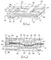
- FIG. 1 shows a portion of a cylinder head gasket 10 of the type Multilayer.
- These sheets comprise two plates 12 and 14 lower and upper, in this case plates each provided with a rib 16 and 18.
- a stopper 22 On the side of the cylinder hole 20, there is provided a stopper 22, peripheral, interposed between the two lower and upper plates.
- This stopper is made in one piece 24, coming from casting or machining.
- This stopper 22 is provided with a housing 28. This accommodation is obtained by any medium, such as casting, stamping, machining, stamping.
- the total height leads to a thickness E.
- a sensor 30 is disposed in this housing, resting or secured to the plate lower.
- the housing 28 is advantageously open on the cylinder hole 20 by one 32 of its sides, opening into the combustion chamber.
- the senor can be in direct contact with the atmosphere prevailing in said room, which allows measurements of different parameters according to the nature of the sensor.
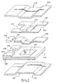
- the housing 28 also has a passage 34 of son 36, vis-à-vis the 32 open side.
- These wires 36 are connected to the sensor 30. They comprise an extension possibly in a flat cladding 38, for example molded having a section in double baffles. This section can also be defined by a U with 40 branches open and 42 flat bottom.
- the minimum configuration cylinder head gasket as described further comprises a base plate 44, plate to which is joined the stopper, mounted floating in this first embodiment.
- This base plate has a window 46 to the right of the son 36 of the sensor 30 and in alignment with the housing 28.
- This window is of suitable dimensions to receive the double baffle of the branches 40 and the bottom 42.
- the thickness e1 of the base plate is greater than the thickness of the wires 36, including in their cladding 38.
- interlay plate comprises a bridge 50 and two windows 52, 54 open, disposed on either side of this bridge.
- Both windows are oriented to come over the sensor wires 36 and more particularly of its cladding 38.
- the bridging is arranged to be positioned above the flat bottom 42, allowing the two branches 40 to pass on both sides.
- the thickness e2 of the intermediate plate is greater than the thickness of the wires 36, including in their cladding 38.
- the sum of the thickness e1 of the base plate and the thickness e2 of the intermediate plate remains less than the thickness E of the stopper.
- the son 36 and their possible sheathing 38 pass through the double baffled channel resulting from the geometries of the different parts constituting the cylinder head gasket.
- the stopper takes up the clamping forces between the motor unit BM and the breech CU .
- the bottom plate 12 and upper 14 seal the right of the stopper in the sensor area.
- a filling material is preferably attached to the sensor 30, in the housing 28 on the one hand to immobilize it and on the other hand to ensure the first sealing barrier in the most efficient manner.
- the second sealing barrier it is also realized in the right ribs.
- the rib 16 of the lower plate 12 comes under pressure on the base plate 44 and the rib 18 comes under pressure on the upper plate 14.
- FIGS. 4, 5 and 6 show a variant in which the elements identical and having the same functions bear the same references increased by 100.
- the base plate 144 is a thick plate with the stopper 122 integrated, that is to say leading to a monolithic assembly.
- This base plate comprises a window 146 substantially identical to the window 46 except that the support edges of the wires 136 with a sheath 138 on the window are chamfered.
- the intermediate plate 154 is of the thin plate type so that all the thicknesses is less than the thickness to the right of the stopper, as previously. Its thickness is substantially that of the threads 136.
- This plate comprises the right of the double chicane, the right of the flat bottom 142, a bridging 150, projecting, which is in profile substantially conjugated with that of the window 146 of the base plate.
- the assembly is identical to the previous one, it is advisable to adapt the profile of ribs 116 and 118 so that the pressure forces exert well on both lower and upper plates.
- Seals are respected and the seal can fulfill its function first between the engine block and the cylinder head.
- the object of the present invention is achieved since the wires emerge from the cylinder head gasket in the thickness of which they are embedded, transmitting the sensor information to a central datalogger and processing, this without ever being subject to compression to generate degradations.
- the radius of curvature at the right of the baffle is compatible with the allowed bending radii, without disturbing the information circulating there.
- the edges of the different windows and housing may be chamfered or radiated as required.
Landscapes
- Engineering & Computer Science (AREA)
- General Engineering & Computer Science (AREA)
- Mechanical Engineering (AREA)
- Gasket Seals (AREA)
- Cylinder Crankcases Of Internal Combustion Engines (AREA)
- Measuring Fluid Pressure (AREA)
- Investigating Or Analyzing Materials By The Use Of Electric Means (AREA)
- Combined Controls Of Internal Combustion Engines (AREA)
Abstract
Description
La présente invention concerne un agencement d'un capteur et de ses connexions filaires dans un joint de culasse métallique, multifeuilles.The present invention relates to an arrangement of a sensor and its connections wired in a metallic cylinder head gasket, multiple sheets.
Les moteurs à explosion interne deviennent de plus en plus pointus et de plus en plus contrôlés tant dans la fabrication des pièces qui le composent mais aussi dans le fonctionnement une fois monté et mis en service.Internal combustion engines are getting more and more sharp and more and more more controlled both in the manufacture of parts that compose it but also in operation once mounted and put into operation.
C'est ainsi que la combustion est un point important non seulement pour améliorer le rendement et les performances de ces moteurs mais aussi dans un souci de limiter la pollution.This is how burning is an important point not only for improve the performance and performance of these engines but also in a concern to limit pollution.
On arrive à ce résultat en dosant parfaitement les quantités de carburant et de comburant, le moment, le lieu d'introduction et les circulations avant et après explosion, en limitant les zones mortes, en contrôlant avec grande précision les hauteurs de joint et en maítrisant l'explosion, notamment.We arrive at this result by perfectly dosing the quantities of fuel and oxidant, the time, the place of introduction and the circulations before and after explosion, by limiting the dead zones, by controlling with great precision the seal heights and controlling the explosion, in particular.
Les carburants eux-mêmes ont été améliorés.The fuels themselves have been improved.
Nombre de ces paramètres dépend des conditions de fonctionnement du moteur comme la température de l'air extérieur, la température du mélange avant introduction dans la chambre de combustion, la température du moteur, la température des gaz de sortie, et tous les paramètres de charge du moteur suivant la charge du véhicule et le type de conduite.Many of these parameters depend on engine operating conditions like the temperature of the outside air, the temperature of the mixture before introduction into the combustion chamber, the engine temperature, the exhaust gas temperature, and all engine load parameters depending on the load of the vehicle and the type of driving.
De nombreux capteurs sont prévus pour mesurer ces paramètres et les transmettre par fibres ou par fils indépendants ou à travers un bus jusqu'à une centrale d'acquisition et de commande. Many sensors are provided to measure these parameters and the transmit by fiber or independent wire or through a bus to a central acquisition and control.
Ces capteurs sont de type connu et disposés en différents endroits du moteur, en piquage sur les différents circuits fluides et dans des logements ménagés dans le bloc moteur et dans la culasse, à partir de l'extérieur.These sensors are of known type and arranged in different places of the engine, in quilting on the various fluid circuits and in housings in the engine block and in the cylinder head, from the outside.
Par contre, on ne dispose pas des paramètres qui sont les plus importants à savoir, la température et la pression par exemple, au sein même de la chambre de combustion et aucune indication sur les oscillations de la culasse par rapport au bloc moteur ou sur les évolutions du serrage ou de la fatigue du joint de culasse et de ses constantes élastiques au cours du temps.However, we do not have the parameters that are the most important to know, temperature and pressure for example, even within the chamber of combustion and no indication of the oscillations of the cylinder head with respect to engine block or changes in the tightening or fatigue of the cylinder head gasket and its elastic constants over time.
Or c'est précisément en cet endroit qu'il convient de mesurer avec exactitude tous ces paramètres si l'on souhaite assurer un pilotage amélioré et plus précis.But it is precisely here that it is necessary to measure accurately all these parameters if one wishes to ensure an improved and more precise steering.
Ceci va dans le sens d'une optimisation du rendement du cycle de combustion et une diminution de la pollution par une limitation du volume d'imbrûlés rejetés.This is in the sense of optimizing the efficiency of the combustion cycle and a reduction in pollution by limiting the volume of unburnt emissions.
Par contre, le problème est de disposer un ou plusieurs capteurs à proximité immédiate de chaque chambre de combustion d'un moteur à explosion, c'est-à-dire au contact direct du volume intérieur de cette chambre sachant que celle-ci doit rester parfaitement close, qu'il faut que chaque capteur n'engendre pas de modification des paramètres mécaniques et notamment ne nécessite pas de surépaisseurs.However, the problem is to have one or more sensors nearby immediately of each combustion chamber of an internal combustion engine, that is to say in direct contact with the interior volume of this room knowing that it must remain perfectly closed, that it is necessary that each sensor does not generate modification of the mechanical parameters and in particular does not require any extra thickness.
Une localisation attractive permettant de répondre à ces impératifs est une localisation dans le joint de culasse. Le joint de culasse est une pièce interface parfaite par sa situation par rapport à la chambre de combustion.An attractive location to meet these imperatives is a location in the cylinder head gasket. The cylinder head gasket is an interface piece perfect by its location in relation to the combustion chamber.
De plus, une modification du joint de culasse et une adaptation d'un capteur ne sont pas une chose facile mais cela est réalisable alors que dans le cas du bloc moteur, la difficulté est de réaliser ensuite l'étanchéité du passage.In addition, modification of the cylinder head gasket and adaptation of a sensor are not an easy thing but this is achievable whereas in the case of the block engine, the difficulty is to then achieve the sealing of the passage.
C'est en effet là que se pose le problème le plus important car une fois un capteur mis en place, il faut pouvoir le relier à la centrale d'acquisition et de commande, ceci nécessairement par une fibre ou un fil. This is where the most important problem arises because once a sensor installed, it must be able to connect it to the central data acquisition and control, this necessarily by a fiber or a wire.
L'agencement selon la présente invention utilise le joint de culasse comme lieu d'implantation d'au moins un capteur, quel que soit le paramètre physique mesuré et propose une solution pour le passage des fibres ou des fils.The arrangement according to the present invention uses the cylinder head gasket as a place of implantation of at least one sensor, regardless of the physical parameter measured and proposes a solution for the passage of fibers or son.
Pour la suite de la description, le terme fil sera utilisé pour désigner indifféremment un conducteur à base de fil électrique du type cuivre placé dans une gaine isolante thermiquement et électriquement ou une ou plusieurs fibres optiques également placées dans une gaine isolante thermiquement et électriquement, ou conducteur souple plat imprimé.For the rest of the description, the term wire will be used to designate indifferently a conductor-based copper-type electrical wire placed in a thermally and electrically insulating sheath or one or more fibers optics also placed in a thermally insulating sheath and electrically, or printed flat flexible conductor.
Il est en effet nécessaire de pouvoir conduire le fil à travers le joint de culasse, de la chambre de combustion jusqu'à la périphérie du joint de culasse pour le relier à la centrale d'acquisition et de commande.It is indeed necessary to be able to lead the wire through the cylinder head gasket, from the combustion chamber to the periphery of the cylinder head gasket for connect to the central acquisition and control.
Il faut que le fil ne soit pas soumis aux pressions de serrage du joint de culasse pour ne pas être dégradé et que le fil ne perturbe pas la fonction première de ce joint, l'étanchéité entre la culasse et le bloc moteur.The wire must not be subjected to the tightening pressures of the cylinder head gasket not to be degraded and that the wire does not disturb the primary function of this seal, the seal between the cylinder head and the engine block.
On connaít déjà des demandes de brevet dans lesquelles on trouve des tentatives de solution qui restent non satisfaisantes.We already know patent applications in which we find attempts of solution that remain unsatisfactory.
Dans la demande de brevet japonais JP-9195814, le joint de culasse utilisé est un joint multifeuilles. Il est prévu un capteur, disposé à proximité immédiate du bord du trou de cylindre. Les fils quant à eux sont disposés dans une gorge ménagée dans l'épaisseur d'une première plaque du joint. Une matière compressible, solidaire d'une seconde feuille, vient se superposer à cette gorge pour maintenir les fils en place dans la gorge.In the Japanese patent application JP-9195814, the cylinder head gasket used is a multifibre seal. It is provided a sensor, disposed in the immediate vicinity of the edge of the cylinder hole. The threads are arranged in a throat formed in the thickness of a first joint plate. Material compressible, attached to a second leaf, is superimposed on this throat to hold the wires in place in the throat.
Par le brevet américain US- 5 659 132, on connaít un système de capteurs permettant les mesures des paramètres dans la chambre de combustion avec une sortie des signaux mesurés en dehors du bloc moteur, en utilisant le joint de culasse pour permettre le passage des fils de liaison. US Pat. No. 5,659,132 discloses a sensor system. allowing measurements of the parameters in the combustion chamber with a output of measured signals outside the motor block, using the seal of cylinder head to allow passage of the connecting wires.
Les moyens utilisés consistent en des tubes rigides de diamètre supérieur à celui du ou des conducteurs y sont logés, l'espace périphérique vide étant comblé par un matériau isolant.The means used consist of rigid tubes of diameter greater than that conductor (s) are accommodated therein, the empty peripheral space being filled by an insulating material.
Un tel montage donne satisfaction mais nécessite un usinage des pièces en vis-à-vis pour former des gorges aptes à recevoir chaque tube.Such an assembly is satisfactory but requires machining parts vis-à-vis to form grooves adapted to receive each tube.
Ceci est coûteux et reste d'une grande précision incompatible avec une fabrication industrielle, en grande série.This is expensive and remains of high accuracy incompatible with a industrial manufacturing, in large series.
L'invention résout les problèmes ci-dessus par l'aménagement d'une chicane entre une plaque de base et une plaque intermédiaire pour le passage des fils suivant cette chicane, comme décrit dans la revendication 1.The invention solves the above problems by providing a baffle between a base plate and a plate intermediate for the passage of son following this baffle, as described in claim 1.
L'agencement selon la présente invention est maintenant décrit en détail selon un mode de réalisation préférentiel et ses variantes.The arrangement according to the present invention is now described in detail according to a preferential embodiment and its variants.
Cette description est établie en regard des dessins annexés sur lesquels les différentes figures représentent ;
- figure 1, une vue en perspective d'une portion de joint de culasse multifeuilles avec un capteur et une superposition de certaines feuilles,
- figure 2, une vue en éclaté des éléments constituant la portion de joint de culasse multifeuilles avec un capteur de la figure 1,
- figure 3, une vue en coupe de la portion de joint de culasse multifeuilles avec un capteur tel que montré sur la figure 1,
- figure 4, une vue en perspective d'une variante de réalisation d'une portion de joint de culasse multifeuilles avec un capteur et superposition de certaines feuilles,
- figure 5, une vue en éclaté des différents éléments de la partie de joint de la figure 4,
- figure 6, une vue en coupe de la portion de joint des figures 4 et 5.
- FIG. 1 is a perspective view of a portion of multi-leaf head gasket with a sensor and a superposition of certain sheets,
- FIG. 2 is an exploded view of the elements constituting the multi-sheet head gasket portion with a sensor of FIG. 1,
- FIG. 3 is a sectional view of the multi-leaf head gasket portion with a sensor as shown in FIG. 1,
- FIG. 4, a perspective view of an alternative embodiment of a multi-leaf head gasket portion with a sensor and superposition of certain sheets,
- FIG. 5, an exploded view of the various elements of the joint part of FIG. 4,
- Figure 6 is a sectional view of the joint portion of Figures 4 and 5.
Sur la figure 1, on a représenté une portion d'un joint de culasse 10 du type
multifeuilles. Ces feuilles comprennent deux plaques 12 et 14 inférieure et
supérieure, en l'occurrence des plaques munies chacune d'une nervure 16 et 18.FIG. 1 shows a portion of a
Du côté du trou de cylindre 20, il est prévu un stoppeur 22, périphérique,
interposé entre les deux plaques inférieure et supérieure. On the side of the
Ce stoppeur est réalisé en une seule pièce 24, venue de fonderie ou d'usinage.This stopper is made in one
Ce stoppeur 22 est muni d'un logement 28. Ce logement est obtenu par tout
moyen, tel que réserve au coulage, emboutissage, usinage, estampage.This
La hauteur totale conduit à une épaisseur E.The total height leads to a thickness E.
Un capteur 30 est disposé dans ce logement, reposant ou solidarisé à la plaque
inférieure. Le logement 28 est avantageusement ouvert sur le trou de cylindre
20 par l'un 32 de ses côtés, débouchant dans la chambre de combustion.A
Ainsi, le capteur peut être au contact direct de l'ambiance régnant dans ladite chambre, ce qui autorise des mesures des différents paramètres en fonction de la nature du capteur.Thus, the sensor can be in direct contact with the atmosphere prevailing in said room, which allows measurements of different parameters according to the nature of the sensor.
Le logement 28 comporte aussi un passage 34 de fils 36, en vis-à-vis du côté 32
ouvert. Ces fils 36 sont reliés au capteur 30. Ils comprennent une prolongation
éventuellement dans un gainage plat 38, par exemple moulé ayant une section en
double chicanes. Cette section peut aussi se définir par un U à branches 40
ouvertes et à fond 42 plat.The
Le joint de culasse à configuration minimale tel que décrit comprend en outre une
plaque de base 44, plaque à laquelle est accolée le stoppeur, monté flottant dans
ce premier mode de réalisation.The minimum configuration cylinder head gasket as described further comprises a
Cette plaque de base comporte une fenêtre 46 au droit des fils 36 du capteur
30 et dans l'alignement du logement 28.This base plate has a
Cette fenêtre est de dimensions adaptées pour recevoir la double chicane des
branches 40 et du fond 42. L'épaisseur e1 de la plaque de base est supérieure à
l'épaisseur des fils 36, y compris dans leur gainage 38.This window is of suitable dimensions to receive the double baffle of the
Sur cette plaque de base 44 est disposée une plaque intercalaire 48. Cette
plaque intercalaire comprend un pontage 50 et deux fenêtres 52, 54 ouvertes,
disposées de part et d'autre de ce pontage.On this
Les deux fenêtres sont orientées pour venir au-dessus des fils 36 du capteur et
plus particulièrement de son gainage 38. Both windows are oriented to come over the
Le pontage est ménagé pour venir se positionner au dessus du fond plat 42,
laissant passer de part et d'autre les deux branches 40.The bridging is arranged to be positioned above the flat bottom 42,
allowing the two
L'épaisseur e2 de la plaque intermédiaire est supérieure à l'épaisseur des fils
36, y compris dans leur gainage 38.The thickness e2 of the intermediate plate is greater than the thickness of the
La somme de l'épaisseur e1 de la plaque de base et de l'épaisseur e2 de la plaque intermédiaire reste inférieure à l'épaisseur E du stoppeur.The sum of the thickness e1 of the base plate and the thickness e2 of the intermediate plate remains less than the thickness E of the stopper.
On note dans l'agencement particulier selon l'invention, représenté en coupe sur
la figure 3, que la nervure 16 de la plaque inférieure 12 vient en appui sur la
plaque de base 44 et obture la fenêtre 46 et que la nervure 18 de la plaque
supérieure 14 vient en appui sur le pontage 50.We note in the particular arrangement according to the invention, shown in section on
3, that the
On constate qu'avec un tel agencement, les fils 36 et leur gainage éventuel 38
passent dans le canal à double chicane résultant des géométries des différentes
pièces constituant le joint de culasse.It is found that with such an arrangement, the
L'étanchéité n'est pas perturbée par cet agencement, dans la zone qui intéresse la présente invention car pour le reste de la surface du joint, les règles habituelles et les comportements associés s'appliquent.The watertightness is not disturbed by this arrangement, in the zone of interest the present invention because for the rest of the joint surface, the rules and the associated behaviors apply.
En effet, on constate que le stoppeur reprend les efforts de serrage entre le
bloc moteur BM et la culasse CU. Les plaques inférieure 12 et supérieure 14
assurent l'étanchéité au droit de ce stoppeur, dans la zone du capteur. Un
matériau de remplissage est de préférence rapporté sur le capteur 30, dans le
logement 28 d'une part pour l'immobiliser et d'autre part pour assurer la
première barrière d'étanchéité de la façon la plus efficace qui soit.Indeed, it is found that the stopper takes up the clamping forces between the motor unit BM and the breech CU . The
Quant à la seconde barrière d'étanchéité elle est également réalisée au droit
des nervures. Ainsi la nervure 16 de la plaque inférieure 12 vient en pression sur
la plaque de base 44 et la nervure 18 vient en pression sur la plaque supérieure
14.As for the second sealing barrier, it is also realized in the right
ribs. Thus the
On constate aussi que les fils ne sont pas mis en compression. We also note that the son are not put in compression.
Afin de compléter les volumes libres autour des fils et pour assurer un maintien de ceux-ci, il est possible d'introduire un polymère, de préférence du type élastomère apte à résister à la température.To complete the free volumes around the wires and to maintain of these, it is possible to introduce a polymer, preferably of the type elastomer capable of withstanding the temperature.
Sur les figures 4, 5 et 6, on a représenté une variante dans laquelle les éléments identiques et ayant les mêmes fonctions portent les mêmes références augmentées de 100.FIGS. 4, 5 and 6 show a variant in which the elements identical and having the same functions bear the same references increased by 100.
Dans ce mode de réalisation, la plaque de base 144 est une plaque épaisse avec le
stoppeur 122 intégré, c'est-à-dire conduisant à un ensemble monolithique.In this embodiment, the
Cette plaque de base comprend une fenêtre 146 sensiblement identique à la
fenêtre 46 à ceci près que les bords d'appui des fils 136 avec un gainage 138 sur
la fenêtre sont chanfreinés.This base plate comprises a
La plaque intermédiaire 154 est du type plaque mince pour que l'ensemble des
épaisseurs soit inférieur à l'épaisseur au droit du stoppeur, comme
précédemment. Son épaisseur est sensiblement celle des fils 136.The
Cette plaque comprend au droit de la double chicane, au droit du fond plat 142,
un pontage 150, en saillie, qui est de profil sensiblement conjugué avec celui de la
fenêtre 146 de la plaque de base.This plate comprises the right of the double chicane, the right of the
Le montage est identique au précédent, il convient d'adapter le profil des
nervures 116 et 118 pour que les efforts de pression s'exercent bien sur les deux
plaques inférieure et supérieure.The assembly is identical to the previous one, it is advisable to adapt the profile of
Dans cet agencement, comme montré spécifiquement sur la figure 4, avec l'assemblage monté, les fils avec le passage en chicane ne présentent aucun risque d'écrasement, y compris dans le temps puisque aucun élément ne vient en appui.In this arrangement, as shown specifically in FIG. 4, with assembled assembly, the wires with the passage in baffle do not present any risk of crushing, including over time since no element comes into support.
Les étanchéités sont respectées et le joint peut donc remplir sa fonction première entre le bloc moteur et la culasse.Seals are respected and the seal can fulfill its function first between the engine block and the cylinder head.
On note que la fabrication industrielle de telles plaques est aisée. Les produits représentés schématiquement sur les figures doivent être adaptés par l'homme de l'art pour que les découpes complémentaires soient réalisées directement lors de l'emboutissage de la feuille complète, si bien que l'agencement selon l'invention n'engendre aucune opération supplémentaire.It is noted that the industrial manufacture of such plates is easy. Products schematically represented on the figures must be adapted by the man of art so that complementary cuts are made directly during stamping of the complete sheet, so that the arrangement according to the invention does not generate any additional operation.
On constate également que le but de la présente invention est atteint puisque les fils émergent du joint de culasse dans l'épaisseur duquel ils sont noyés, transmettant ainsi les informations du capteur jusqu'à une centrale d'acquisition et de traitement, ceci sans jamais être soumis à une compression susceptible d'engendrer des dégradations.It can also be seen that the object of the present invention is achieved since the wires emerge from the cylinder head gasket in the thickness of which they are embedded, transmitting the sensor information to a central datalogger and processing, this without ever being subject to compression to generate degradations.
Dans le cas où les fils sont des fibres optiques, le rayon de courbure au droit de la chicane est compatible avec les rayons de courbure autorisés, sans perturber l'information qui y circule. Les bords des différentes fenêtres et logements peuvent être chanfreinés ou rayonnés suivant les besoins.In the case where the yarns are optical fibers, the radius of curvature at the right of the baffle is compatible with the allowed bending radii, without disturbing the information circulating there. The edges of the different windows and housing may be chamfered or radiated as required.
Claims (9)
- Arrangement for a multiple-plate cylinder head gasket (10) comprising at least two plates (12, 14; 112, 114), a lower one and an upper one with ribs (16, 18; 116, 118), a base plate (44; 144) and an intermediate plate (48; 148) comprising a sensor (30, 130) disposed in the intermediate proximity of the cylinder hole edge (20, 120) and wires (36, 136) for the transmission of data coming from this sensor, characterized in that it consists in forming a chicane (46, 52, 54; 146, 152, 154) between the base plate and the intermediate plate for the passage of the said wires (36; 136) following this chicane.
- Arrangement for a multiple-plate cylinder head gasket (10) according to Claim 1, characterized in that the base plate (44; 144) comprises a window (46; 146) in alignment with the wires (36; 136) of the sensor (30; 130) and the intermediate plate (48; 148) comprises a bridging (50; 150) and two open windows (52, 54; 152, 154), disposed on either side of this bridging.
- Arrangement for a multiple-plate cylinder head gasket (10) according to Claim 2, characterized in that the bridging (50; 150) is formed such that it becomes positioned over the wires passing through a chicane with a flat bottom (42; 142) and two branches (40; 140).
- Arrangement for a multiple-plate cylinder head gasket (10) according to Claim 3, characterized in that the intermediate plate (48) has a thickness greater than that of the wires and in that the bridging (50) is in the plane of this intermediate plate (48).
- Arrangement for a multiple-plate cylinder head gasket (10) according to Claim 3, characterized in that the intermediate plate (148) has a thickness substantially equal to that of the wires and in that the bridging (150) protrudes into the window (146) of the base plate (144).
- Arrangement for a multiple-plate cylinder head gasket (10) according to any one of the preceding claims, characterized in that it comprises a stopper (22, 122), disposed between the ribbed plates (12, 14; 112, 114) and in alignment with the base plate (44; 144) and the intermediate plate (48, 148), the height E of this stopper being greater than the sum of the heights e1 of the base plate and e2 of the intermediate plate.
- Arrangement for a multiple-plate cylinder head gasket (10) according to Claim 6, characterized in that the stopper (22, 122) comprises a housing (28, 128) for housing the sensor (30, 130), this housing being open on one side (32, 132) facing the cylinder hole (20, 120) and comprising a passage (34, 134).
- Arrangement for a multiple-plate cylinder head gasket (10) according to Claim 7, characterized in that the free spaces around the sensor in the housing (28, 128) are filled.
- Arrangement for a multiple-plate cylinder head gasket (10) according to one of Claims 6, 7 or 8, characterized in that the stopper (22, 122) is mounted such that it is floating with respect to the plates.
Applications Claiming Priority (3)
| Application Number | Priority Date | Filing Date | Title |
|---|---|---|---|
| FR0208527 | 2002-07-08 | ||
| FR0208527A FR2841938B1 (en) | 2002-07-08 | 2002-07-08 | ARRANGEMENT OF A SENSOR AND ITS WIRED CONNECTIONS IN A MULTI-LEAF METAL HEAD GASKET |
| PCT/EP2003/006922 WO2004005772A1 (en) | 2002-07-08 | 2003-06-30 | Arrangement for a sensor and its wire connections in a multiple-plate metal cylinder-head gasket |
Publications (2)
| Publication Number | Publication Date |
|---|---|
| EP1520128A1 EP1520128A1 (en) | 2005-04-06 |
| EP1520128B1 true EP1520128B1 (en) | 2005-12-21 |
Family
ID=29725246
Family Applications (1)
| Application Number | Title | Priority Date | Filing Date |
|---|---|---|---|
| EP03762555A Expired - Lifetime EP1520128B1 (en) | 2002-07-08 | 2003-06-30 | Arrangement for a sensor and its wire connections in a multiple-plate metal cylinder-head gasket |
Country Status (9)
| Country | Link |
|---|---|
| US (1) | US20060055117A1 (en) |
| EP (1) | EP1520128B1 (en) |
| JP (1) | JP4178147B2 (en) |
| CN (1) | CN100383437C (en) |
| AT (1) | ATE313745T1 (en) |
| AU (1) | AU2003252533A1 (en) |
| DE (1) | DE60302899T2 (en) |
| FR (1) | FR2841938B1 (en) |
| WO (1) | WO2004005772A1 (en) |
Families Citing this family (3)
| Publication number | Priority date | Publication date | Assignee | Title |
|---|---|---|---|---|
| US4874802A (en) * | 1988-06-16 | 1989-10-17 | Mobay Corporation | Polycarbonate compositions resistant to gamma radiation |
| JP2005090722A (en) * | 2003-09-19 | 2005-04-07 | Uchiyama Mfg Corp | Multifunctional gasket |
| US8371156B2 (en) * | 2009-06-01 | 2013-02-12 | Federal-Mogul Corporation | Compression sensor gasket assembly and method of construction |
Family Cites Families (12)
| Publication number | Priority date | Publication date | Assignee | Title |
|---|---|---|---|---|
| FR2465077A1 (en) * | 1979-09-14 | 1981-03-20 | Thomson Csf | DEVICE FOR INSERTING A SENSOR IN THE EXHAUST DUCTWORK OF AN INTERNAL COMBUSTION ENGINE AND REGULATOR SYSTEM FOR FUEL ASSAY IMPLEMENTING SUCH A DEVICE |
| US5195365A (en) * | 1990-08-24 | 1993-03-23 | Toyota Jidosha Kabushiki Kaisha | Device for detecting combustion pressure of an internal combustion engine |
| US5659132A (en) | 1995-03-07 | 1997-08-19 | Fel-Pro Incorporated | Gasket enclosed sensor system |
| JPH09195814A (en) | 1996-01-18 | 1997-07-29 | Nippon Reinz Co Ltd | Cylinder head gasket with sensor |
| JPH1194676A (en) * | 1997-09-17 | 1999-04-09 | Hitachi Ltd | In-cylinder pressure sensor |
| CN1147721C (en) * | 1999-03-19 | 2004-04-28 | 中国船舶工业总公司第七研究院第七一一研究所 | Abnormal combustion detecting method and warning device for air cylinder of gas engine |
| CN2485639Y (en) * | 2000-07-28 | 2002-04-10 | 武汉理工大学 | Temperature sensor for engine cylinder inner wall |
| JP2002276809A (en) * | 2001-03-15 | 2002-09-25 | Taiho Kogyo Co Ltd | Cylinder head gasket |
| CA2476095A1 (en) * | 2002-02-15 | 2003-08-28 | Dana Corporation | Multiple-layer cylinder head gasket with integral pressure sensor apparatus for measuring pressures within engine cylinders |
| US6739183B1 (en) * | 2002-02-15 | 2004-05-25 | Dana Corporation | Multiple-layer cylinder head gasket with integral pressure sensor apparatus for measuring pressures within engine cylinders |
| US6701775B1 (en) * | 2002-02-15 | 2004-03-09 | Dana Corporation | Pressure sensor apparatus for measuring pressures including knock conditions in engine cylinders |
| BR0307732A (en) * | 2002-02-15 | 2005-04-26 | Dana Corp | Combustion Pressure Sensor and Gasketing Method |
-
2002
- 2002-07-08 FR FR0208527A patent/FR2841938B1/en not_active Expired - Fee Related
-
2003
- 2003-06-30 JP JP2004518632A patent/JP4178147B2/en not_active Expired - Fee Related
- 2003-06-30 WO PCT/EP2003/006922 patent/WO2004005772A1/en active IP Right Grant
- 2003-06-30 AT AT03762555T patent/ATE313745T1/en not_active IP Right Cessation
- 2003-06-30 CN CNB038161095A patent/CN100383437C/en not_active Expired - Fee Related
- 2003-06-30 EP EP03762555A patent/EP1520128B1/en not_active Expired - Lifetime
- 2003-06-30 US US10/520,443 patent/US20060055117A1/en not_active Abandoned
- 2003-06-30 DE DE60302899T patent/DE60302899T2/en not_active Expired - Lifetime
- 2003-06-30 AU AU2003252533A patent/AU2003252533A1/en not_active Abandoned
Also Published As
| Publication number | Publication date |
|---|---|
| AU2003252533A1 (en) | 2004-01-23 |
| DE60302899D1 (en) | 2006-01-26 |
| DE60302899T2 (en) | 2006-08-03 |
| CN1666047A (en) | 2005-09-07 |
| JP4178147B2 (en) | 2008-11-12 |
| US20060055117A1 (en) | 2006-03-16 |
| FR2841938B1 (en) | 2004-08-27 |
| WO2004005772A1 (en) | 2004-01-15 |
| ATE313745T1 (en) | 2006-01-15 |
| FR2841938A1 (en) | 2004-01-09 |
| JP2006507438A (en) | 2006-03-02 |
| EP1520128A1 (en) | 2005-04-06 |
| CN100383437C (en) | 2008-04-23 |
Similar Documents
| Publication | Publication Date | Title |
|---|---|---|
| FR2986321A1 (en) | SENSOR SYSTEM AND METHOD FOR MANUFACTURING SAME | |
| FR2866431A1 (en) | GAS DETECTOR COMPRISING A GAS INLET DESIGNED TO CREATE A DESIRED GAS FLOW | |
| FR2899683A1 (en) | TEMPERATURE SENSOR AND METHOD OF MANUFACTURING THE SAME | |
| WO2008095737A1 (en) | Device for protecting an air filter, particularly of an electricity generator set, comprising parts to be assembled with the filter radially | |
| FR3069579A1 (en) | ACOUSTIC PANEL AND ASSOCIATED PROPULSIVE ASSEMBLY | |
| FR2816003A1 (en) | EXHAUST MANIFOLD ISOLATED BY AN AIR SLIT FOR AN INTERNAL COMBUSTION ENGINE | |
| FR3047769A1 (en) | OIL JET OF SIMPLIFIED MANUFACTURE | |
| EP1520128B1 (en) | Arrangement for a sensor and its wire connections in a multiple-plate metal cylinder-head gasket | |
| EP2256330A1 (en) | Intake noise damper of an internal combustion engine, and intake conduit comprising same | |
| EP0753689A1 (en) | Gasket for internal combustion engine, especially cylinder head gasket | |
| EP0095989A1 (en) | Fluid sealing system for the cylinder head gasket of an internal-combustion engine | |
| FR2831210A1 (en) | Integrated engine combustion monitoring system has light communication channel through which light signal received by sensor, propagates to electronic system | |
| FR2849198A1 (en) | Detector construction, for vehicle exhaust gases, has cylindrical casing with porcelain insulators, detection element and end caps | |
| EP1905971B1 (en) | Device for separating certain materials produced by an internal combustion engine. | |
| WO2005022088A1 (en) | Universal actuator particularly for dashboards | |
| FR2849199A1 (en) | Vehicle exhaust gas sensor construction, designed to avoid thermal damage to sealed joint, includes resilient seal and support under permanent compression | |
| EP0391014B1 (en) | Absorption silencer for internal combustion engines, especially for all-terrain vehicles | |
| CA2455367A1 (en) | Cylinder-head gasket comprising an edge-to-edge stop ring | |
| EP1495214B1 (en) | Exhaust chamber comprising an envelope defining a gas circulation passage | |
| EP0508891B1 (en) | Method of making a device for controlling the intake air of motor vehicles comprising a thermistor for measuring the temperature of the intake air and device made according to this method | |
| EP1469207A1 (en) | Device of coupling by fitment between two elements | |
| FR2686690A1 (en) | Sensor system comprising a plunger intended to be placed in the bore of a support | |
| EP3109518B1 (en) | Assembly of seal and housing with clamping of an electrical harness | |
| FR3059060A1 (en) | DEVICE FOR MAINTAINING AN ELECTRIC MOTOR IN AN ACTUATOR BODY | |
| EP0092469B1 (en) | Bleeder means for a cylinder-piston assembly and brake motor equipped with such means |
Legal Events
| Date | Code | Title | Description |
|---|---|---|---|
| PUAI | Public reference made under article 153(3) epc to a published international application that has entered the european phase |
Free format text: ORIGINAL CODE: 0009012 |
|
| 17P | Request for examination filed |
Effective date: 20041217 |
|
| AK | Designated contracting states |
Kind code of ref document: A1 Designated state(s): AT BE BG CH CY CZ DE DK EE ES FI FR GB GR HU IE IT LI LU MC NL PT RO SE SI SK TR |
|
| AX | Request for extension of the european patent |
Extension state: AL LT LV MK |
|
| GRAP | Despatch of communication of intention to grant a patent |
Free format text: ORIGINAL CODE: EPIDOSNIGR1 |
|
| GRAS | Grant fee paid |
Free format text: ORIGINAL CODE: EPIDOSNIGR3 |
|
| GRAA | (expected) grant |
Free format text: ORIGINAL CODE: 0009210 |
|
| AK | Designated contracting states |
Kind code of ref document: B1 Designated state(s): AT BE BG CH CY CZ DE DK EE ES FI FR GB GR HU IE IT LI LU MC NL PT RO SE SI SK TR |
|
| PG25 | Lapsed in a contracting state [announced via postgrant information from national office to epo] |
Ref country code: AT Free format text: LAPSE BECAUSE OF FAILURE TO SUBMIT A TRANSLATION OF THE DESCRIPTION OR TO PAY THE FEE WITHIN THE PRESCRIBED TIME-LIMIT Effective date: 20051221 Ref country code: SI Free format text: LAPSE BECAUSE OF FAILURE TO SUBMIT A TRANSLATION OF THE DESCRIPTION OR TO PAY THE FEE WITHIN THE PRESCRIBED TIME-LIMIT Effective date: 20051221 Ref country code: RO Free format text: LAPSE BECAUSE OF FAILURE TO SUBMIT A TRANSLATION OF THE DESCRIPTION OR TO PAY THE FEE WITHIN THE PRESCRIBED TIME-LIMIT Effective date: 20051221 Ref country code: NL Free format text: LAPSE BECAUSE OF FAILURE TO SUBMIT A TRANSLATION OF THE DESCRIPTION OR TO PAY THE FEE WITHIN THE PRESCRIBED TIME-LIMIT Effective date: 20051221 Ref country code: CZ Free format text: LAPSE BECAUSE OF FAILURE TO SUBMIT A TRANSLATION OF THE DESCRIPTION OR TO PAY THE FEE WITHIN THE PRESCRIBED TIME-LIMIT Effective date: 20051221 Ref country code: IE Free format text: LAPSE BECAUSE OF FAILURE TO SUBMIT A TRANSLATION OF THE DESCRIPTION OR TO PAY THE FEE WITHIN THE PRESCRIBED TIME-LIMIT Effective date: 20051221 Ref country code: SK Free format text: LAPSE BECAUSE OF FAILURE TO SUBMIT A TRANSLATION OF THE DESCRIPTION OR TO PAY THE FEE WITHIN THE PRESCRIBED TIME-LIMIT Effective date: 20051221 Ref country code: FI Free format text: LAPSE BECAUSE OF FAILURE TO SUBMIT A TRANSLATION OF THE DESCRIPTION OR TO PAY THE FEE WITHIN THE PRESCRIBED TIME-LIMIT Effective date: 20051221 |
|
| REG | Reference to a national code |
Ref country code: GB Ref legal event code: FG4D Free format text: NOT ENGLISH |
|
| REG | Reference to a national code |
Ref country code: CH Ref legal event code: EP |
|
| REG | Reference to a national code |
Ref country code: IE Ref legal event code: FG4D Free format text: LANGUAGE OF EP DOCUMENT: FRENCH |
|
| REF | Corresponds to: |
Ref document number: 60302899 Country of ref document: DE Date of ref document: 20060126 Kind code of ref document: P |
|
| PG25 | Lapsed in a contracting state [announced via postgrant information from national office to epo] |
Ref country code: GR Free format text: LAPSE BECAUSE OF FAILURE TO SUBMIT A TRANSLATION OF THE DESCRIPTION OR TO PAY THE FEE WITHIN THE PRESCRIBED TIME-LIMIT Effective date: 20060321 Ref country code: DK Free format text: LAPSE BECAUSE OF FAILURE TO SUBMIT A TRANSLATION OF THE DESCRIPTION OR TO PAY THE FEE WITHIN THE PRESCRIBED TIME-LIMIT Effective date: 20060321 Ref country code: BG Free format text: LAPSE BECAUSE OF FAILURE TO SUBMIT A TRANSLATION OF THE DESCRIPTION OR TO PAY THE FEE WITHIN THE PRESCRIBED TIME-LIMIT Effective date: 20060321 Ref country code: SE Free format text: LAPSE BECAUSE OF FAILURE TO SUBMIT A TRANSLATION OF THE DESCRIPTION OR TO PAY THE FEE WITHIN THE PRESCRIBED TIME-LIMIT Effective date: 20060321 |
|
| PG25 | Lapsed in a contracting state [announced via postgrant information from national office to epo] |
Ref country code: ES Free format text: LAPSE BECAUSE OF FAILURE TO SUBMIT A TRANSLATION OF THE DESCRIPTION OR TO PAY THE FEE WITHIN THE PRESCRIBED TIME-LIMIT Effective date: 20060401 |
|
| PG25 | Lapsed in a contracting state [announced via postgrant information from national office to epo] |
Ref country code: PT Free format text: LAPSE BECAUSE OF FAILURE TO SUBMIT A TRANSLATION OF THE DESCRIPTION OR TO PAY THE FEE WITHIN THE PRESCRIBED TIME-LIMIT Effective date: 20060522 |
|
| NLV1 | Nl: lapsed or annulled due to failure to fulfill the requirements of art. 29p and 29m of the patents act | ||
| PG25 | Lapsed in a contracting state [announced via postgrant information from national office to epo] |
Ref country code: HU Free format text: LAPSE BECAUSE OF FAILURE TO SUBMIT A TRANSLATION OF THE DESCRIPTION OR TO PAY THE FEE WITHIN THE PRESCRIBED TIME-LIMIT Effective date: 20060622 |
|
| GBT | Gb: translation of ep patent filed (gb section 77(6)(a)/1977) |
Effective date: 20060601 |
|
| PG25 | Lapsed in a contracting state [announced via postgrant information from national office to epo] |
Ref country code: BE Free format text: LAPSE BECAUSE OF NON-PAYMENT OF DUE FEES Effective date: 20060630 Ref country code: MC Free format text: LAPSE BECAUSE OF NON-PAYMENT OF DUE FEES Effective date: 20060630 |
|
| PGFP | Annual fee paid to national office [announced via postgrant information from national office to epo] |
Ref country code: IT Payment date: 20060630 Year of fee payment: 4 |
|
| REG | Reference to a national code |
Ref country code: IE Ref legal event code: FD4D |
|
| PLBE | No opposition filed within time limit |
Free format text: ORIGINAL CODE: 0009261 |
|
| STAA | Information on the status of an ep patent application or granted ep patent |
Free format text: STATUS: NO OPPOSITION FILED WITHIN TIME LIMIT |
|
| 26N | No opposition filed |
Effective date: 20060922 |
|
| BERE | Be: lapsed |
Owner name: CARL FREUDENBERG Effective date: 20060630 |
|
| REG | Reference to a national code |
Ref country code: CH Ref legal event code: PL |
|
| GBPC | Gb: european patent ceased through non-payment of renewal fee |
Effective date: 20070630 |
|
| PG25 | Lapsed in a contracting state [announced via postgrant information from national office to epo] |
Ref country code: LI Free format text: LAPSE BECAUSE OF NON-PAYMENT OF DUE FEES Effective date: 20070630 Ref country code: CH Free format text: LAPSE BECAUSE OF NON-PAYMENT OF DUE FEES Effective date: 20070630 |
|
| PG25 | Lapsed in a contracting state [announced via postgrant information from national office to epo] |
Ref country code: GB Free format text: LAPSE BECAUSE OF NON-PAYMENT OF DUE FEES Effective date: 20070630 |
|
| PG25 | Lapsed in a contracting state [announced via postgrant information from national office to epo] |
Ref country code: EE Free format text: LAPSE BECAUSE OF FAILURE TO SUBMIT A TRANSLATION OF THE DESCRIPTION OR TO PAY THE FEE WITHIN THE PRESCRIBED TIME-LIMIT Effective date: 20051221 |
|
| PG25 | Lapsed in a contracting state [announced via postgrant information from national office to epo] |
Ref country code: TR Free format text: LAPSE BECAUSE OF FAILURE TO SUBMIT A TRANSLATION OF THE DESCRIPTION OR TO PAY THE FEE WITHIN THE PRESCRIBED TIME-LIMIT Effective date: 20051221 Ref country code: LU Free format text: LAPSE BECAUSE OF NON-PAYMENT OF DUE FEES Effective date: 20060630 |
|
| PG25 | Lapsed in a contracting state [announced via postgrant information from national office to epo] |
Ref country code: CY Free format text: LAPSE BECAUSE OF FAILURE TO SUBMIT A TRANSLATION OF THE DESCRIPTION OR TO PAY THE FEE WITHIN THE PRESCRIBED TIME-LIMIT Effective date: 20051221 |
|
| PG25 | Lapsed in a contracting state [announced via postgrant information from national office to epo] |
Ref country code: IT Free format text: LAPSE BECAUSE OF NON-PAYMENT OF DUE FEES Effective date: 20070630 |
|
| PGFP | Annual fee paid to national office [announced via postgrant information from national office to epo] |
Ref country code: FR Payment date: 20100630 Year of fee payment: 8 |
|
| REG | Reference to a national code |
Ref country code: DE Ref legal event code: R081 Ref document number: 60302899 Country of ref document: DE Owner name: ELRINGKLINGER AG, DE Free format text: FORMER OWNER: CARL FREUDENBERG, 69469 WEINHEIM, DE Effective date: 20110824 |
|
| REG | Reference to a national code |
Ref country code: FR Ref legal event code: ST Effective date: 20120229 |
|
| PG25 | Lapsed in a contracting state [announced via postgrant information from national office to epo] |
Ref country code: FR Free format text: LAPSE BECAUSE OF NON-PAYMENT OF DUE FEES Effective date: 20110630 |
|
| PGFP | Annual fee paid to national office [announced via postgrant information from national office to epo] |
Ref country code: DE Payment date: 20130621 Year of fee payment: 11 |
|
| REG | Reference to a national code |
Ref country code: DE Ref legal event code: R119 Ref document number: 60302899 Country of ref document: DE |
|
| REG | Reference to a national code |
Ref country code: DE Ref legal event code: R119 Ref document number: 60302899 Country of ref document: DE Effective date: 20150101 |
|
| PG25 | Lapsed in a contracting state [announced via postgrant information from national office to epo] |
Ref country code: DE Free format text: LAPSE BECAUSE OF NON-PAYMENT OF DUE FEES Effective date: 20150101 |