EP1520089B1 - Compresseur d'air de suralimentation a entrainement auxiliaire electrique - Google Patents
Compresseur d'air de suralimentation a entrainement auxiliaire electrique Download PDFInfo
- Publication number
- EP1520089B1 EP1520089B1 EP03761396A EP03761396A EP1520089B1 EP 1520089 B1 EP1520089 B1 EP 1520089B1 EP 03761396 A EP03761396 A EP 03761396A EP 03761396 A EP03761396 A EP 03761396A EP 1520089 B1 EP1520089 B1 EP 1520089B1
- Authority
- EP
- European Patent Office
- Prior art keywords
- exhaust gas
- gas turbocharger
- combustion engine
- drive
- compressor
- Prior art date
- Legal status (The legal status is an assumption and is not a legal conclusion. Google has not performed a legal analysis and makes no representation as to the accuracy of the status listed.)
- Expired - Lifetime
Links
Images

Classifications
-
- F—MECHANICAL ENGINEERING; LIGHTING; HEATING; WEAPONS; BLASTING
- F02—COMBUSTION ENGINES; HOT-GAS OR COMBUSTION-PRODUCT ENGINE PLANTS
- F02B—INTERNAL-COMBUSTION PISTON ENGINES; COMBUSTION ENGINES IN GENERAL
- F02B39/00—Component parts, details, or accessories relating to, driven charging or scavenging pumps, not provided for in groups F02B33/00 - F02B37/00
- F02B39/02—Drives of pumps; Varying pump drive gear ratio
- F02B39/12—Drives characterised by use of couplings or clutches therein
-
- F—MECHANICAL ENGINEERING; LIGHTING; HEATING; WEAPONS; BLASTING
- F02—COMBUSTION ENGINES; HOT-GAS OR COMBUSTION-PRODUCT ENGINE PLANTS
- F02B—INTERNAL-COMBUSTION PISTON ENGINES; COMBUSTION ENGINES IN GENERAL
- F02B37/00—Engines characterised by provision of pumps driven at least for part of the time by exhaust
- F02B37/04—Engines with exhaust drive and other drive of pumps, e.g. with exhaust-driven pump and mechanically-driven second pump
- F02B37/10—Engines with exhaust drive and other drive of pumps, e.g. with exhaust-driven pump and mechanically-driven second pump at least one pump being alternatively or simultaneously driven by exhaust and other drive, e.g. by pressurised fluid from a reservoir or an engine-driven pump
-
- F—MECHANICAL ENGINEERING; LIGHTING; HEATING; WEAPONS; BLASTING
- F02—COMBUSTION ENGINES; HOT-GAS OR COMBUSTION-PRODUCT ENGINE PLANTS
- F02B—INTERNAL-COMBUSTION PISTON ENGINES; COMBUSTION ENGINES IN GENERAL
- F02B37/00—Engines characterised by provision of pumps driven at least for part of the time by exhaust
- F02B37/12—Control of the pumps
-
- F—MECHANICAL ENGINEERING; LIGHTING; HEATING; WEAPONS; BLASTING
- F02—COMBUSTION ENGINES; HOT-GAS OR COMBUSTION-PRODUCT ENGINE PLANTS
- F02B—INTERNAL-COMBUSTION PISTON ENGINES; COMBUSTION ENGINES IN GENERAL
- F02B37/00—Engines characterised by provision of pumps driven at least for part of the time by exhaust
- F02B37/12—Control of the pumps
- F02B37/14—Control of the alternation between or the operation of exhaust drive and other drive of a pump, e.g. dependent on speed
-
- F—MECHANICAL ENGINEERING; LIGHTING; HEATING; WEAPONS; BLASTING
- F02—COMBUSTION ENGINES; HOT-GAS OR COMBUSTION-PRODUCT ENGINE PLANTS
- F02B—INTERNAL-COMBUSTION PISTON ENGINES; COMBUSTION ENGINES IN GENERAL
- F02B39/00—Component parts, details, or accessories relating to, driven charging or scavenging pumps, not provided for in groups F02B33/00 - F02B37/00
- F02B39/02—Drives of pumps; Varying pump drive gear ratio
- F02B39/08—Non-mechanical drives, e.g. fluid drives having variable gear ratio
- F02B39/10—Non-mechanical drives, e.g. fluid drives having variable gear ratio electric
-
- Y—GENERAL TAGGING OF NEW TECHNOLOGICAL DEVELOPMENTS; GENERAL TAGGING OF CROSS-SECTIONAL TECHNOLOGIES SPANNING OVER SEVERAL SECTIONS OF THE IPC; TECHNICAL SUBJECTS COVERED BY FORMER USPC CROSS-REFERENCE ART COLLECTIONS [XRACs] AND DIGESTS
- Y02—TECHNOLOGIES OR APPLICATIONS FOR MITIGATION OR ADAPTATION AGAINST CLIMATE CHANGE
- Y02T—CLIMATE CHANGE MITIGATION TECHNOLOGIES RELATED TO TRANSPORTATION
- Y02T10/00—Road transport of goods or passengers
- Y02T10/10—Internal combustion engine [ICE] based vehicles
- Y02T10/12—Improving ICE efficiencies
Definitions
- Charging devices for internal combustion engines increase the air flow rate of an internal combustion engine by pre-compression of the air required for combustion of the fuel. Through the use of superchargers can achieve higher power densities of internal combustion engines with the same displacement, improved fuel consumption and lower exhaust emissions.
- charging devices which are also generally referred to as "loader”
- mechanical superchargers, exhaust gas turbochargers or pressure wave superchargers are generally used.
- the US 2002/041813 A1 discloses an exhaust gas turbocharger according to the preamble of claim 1.
- pressure wave chargers which may have an electric drive for better individual control in all operating points of the internal combustion engine
- the compressor required for compression of the air required for combustion air compressor power is also obtained from the exhaust gas of the internal combustion engine.
- pressure wave loaders in addition to the flow coupling of the supercharger to the internal combustion engine, mechanical coupling of the supercharger with the internal combustion engine is also required.
- DE 32 25 389 A1 has a device for driving auxiliary equipment in motor vehicles to the object.
- a drive means an internal combustion engine is used, in which a two-stage or multi-stage transmission is connected in the operative connection between the internal combustion engine and the auxiliary equipment to be driven.
- the two- or multi-stage transmission causes an automatic speed-dependent switching such that the auxiliary units with a limited speed range can be coupled to the speed of the Verbrennungslaaftmaschine.
- the auxiliary units are additionally driven by a turbine disposed in the exhaust passage of the internal combustion engine.
- the turbine in the exhaust duct of the internal combustion engine drives a generator to which an electric motor is connected downstream via a power controller.
- an electric motor is connected downstream via a power controller.
- the electric machine can be operated in generator mode and feed unused energy of the exhaust stream into the electrical system of the motor vehicle.
- electrically operable charge air compressors for connection to an internal combustion engine, which comprise an electric motor with a stator and a rotor for driving the compressor wheel of the charge air compressor.
- the compressor wheel is in a compressor wheel housing provided with at least one air inlet and an air outlet.
- the air inlet and the air outlet are connected to each other via a flow channel extending in the compressor housing.
- the charge air compressor is configured such that the compressor wheel in the compressor housing from a working position in a rest position and is displaced back, the compressor wheel can be at least partially removed from the compression section in a shift to the rest position.
- a further development trend is that the turbine part and compressor part of an exhaust gas turbocharger can be rigidly connected to an electric drive and support the drive of the exhaust gas turbocharger by the electric motor during the acceleration phase.
- boost pressure build-up and engine dynamics can be improved, this approach has several disadvantages.
- both the turbine part and the compressor part must be accelerated, although in this phase of operation of the internal combustion engine primarily only the rapid start-up of the compressor wheel is desired. Since both parts, d. H. Turbine part and compressor part of the exhaust gas turbocharger must be accelerated, consequently, the moment of inertia is greater, so that the drive power of the electric drive must be designed correspondingly higher.
- the proposed solution according to the invention realizes a connection between the compressor part of the exhaust gas turbocharger and an auxiliary drive, which only in case of need, ie effective within a critical speed range of the internal combustion engine is.
- the auxiliary drive, z. B. formed as an electric drive is connected to the exhaust gas turbocharger via a freewheel device and an overrunning clutch. Freewheel device and overrunning clutch are integrated in the compressor part of the exhaust gas turbocharger.
- the compressor part of the exhaust gas turbocharger can optionally be supported by the auxiliary drive, ie, in charge-poor map areas. This can be switched on or released as required via the clutch, so that increased drag torques, which occur for reasons of higher drive power in heavily coupled exhaust gas turbocharger systems, can be avoided. Furthermore, it can be achieved by the proposed solution according to the invention that charge pressure impairments due to increased drag torque fail.
- the optional coupling between the compressor part and auxiliary drive enabling clutch allows the electric auxiliary drive depending on the power requirement of the compressor wheel of the exhaust gas turbocharger switched on or regarded as a load to drop.
- the coupling, which is arranged between the turbine part and the compressor part of the exhaust gas turbocharger on the bearing shaft, z. B. can be formed as a multi-plate clutch or as an electromagnetic clutch, which can also take over Synchronisationsfunlctionen.
- the proposed solution according to the invention offers the possibility to accelerate only the compressor part of the exhaust gas turbocharger with an auxiliary drive, so that compared to the solutions of the prior art due to the lower mass moment of inertia only the compressor part of the exhaust gas turbocharger, the drive power of the electric auxiliary drive can be designed correspondingly lower and an improved engine dynamics even in the critical speed range of an internal combustion engine adjusted with exhaust gas turbocharger.
- the invention proposed solution of only the compressor part of an exhaust gas turbocharger in case of need driving electric drive the use of a separate electric turbocompressor in the intake of the internal combustion engine can be bypassed. It can be saved the associated use of precious space and the associated costs.
- FIG. 1 is a schematically illustrated internal combustion engine with exhaust gas turbocharger removable, the compressor part can be connected to a if necessary connectable auxiliary drive.
- Fresh air - indicated by the pointing on a fresh air inlet 1 arrow - is sucked through an intake pipe 3 in the intake tract 2 of an internal combustion engine 10.
- a compressor part 5 of an exhaust gas turbocharger 4 - here only schematically indicated - is arranged on a Querersbbitts extension of the intake manifold 3.
- a Ansaugrohrabites 8 connects, in which enters the over the compressor part 5 pre-compressed intake air.
- the pre-compressed fresh air passing through the intake pipe section 8 is passed through an intercooler 9 directed to cool the pre-compressed fresh air, which is favorable in terms of cylinder filling of the individual cylinders of the internal combustion engine.
- the pre-compressed fresh air leaving the intercooler 9 enters at an inlet 11 into a combustion chamber 12 of the internal combustion engine 10, which is bounded on the one hand by a cylinder wall 13, which is only schematically indicated here, and the end face of a piston 14.
- the higher the precompressed fresh air is compressed the better filling of the combustion chamber 12 of the internal combustion engine can be achieved.
- the internal combustion engine 10 can be both a spark-ignited and a self-igniting multi-cylinder internal combustion engine, which is used both for applications on motor vehicles and for applications on commercial vehicles.
- the piston 14 is connected via a hinged connecting rod 15 with a crankshaft, not shown here, which rotates within a crankcase 16 in the lower region of the internal combustion engine and converts the upward or downward movement of the piston 14 in a rotational movement.
- the turbine part 6 of the exhaust gas turbocharger is connected to the compressor part 5 of the exhaust gas turbocharger via a supercharger shaft 7.
- the supercharger shaft 7 passes through a partition wall 20 which separates the intake tract 2 from the exhaust gas duct 18 of the internal combustion engine 10.
- the exhaust gas entering on the input side via the exhaust gas channel 18 into the turbine part 6 of the exhaust gas turbocharger 4 leaves the turbine part 6 in the radial direction in order to flow off into a muffler 19.
- the exhaust gas flow leaving the combustion chamber 12 of the internal combustion engine 10 is deprived of energy, which is converted into kinetic energy and serves to drive the compressor part 5 of the exhaust gas turbocharger 4 in the intake tract 2 of the internal combustion engine 10.
- compressor part 5 of the exhaust gas turbocharger 4 is coupled via a drive shaft 25 with a motor and a stator comprehensive especially designed as an electric machine self-sufficient auxiliary drive 24.
- auxiliary drive 24 which is preferably designed as an electric drive
- the compressor part 5 of the exhaust gas turbocharger 4 is driven independently of the turbine part 6 of the exhaust gas turbocharger 4, when the exhaust gas entering the exhaust duct 18 on the exhaust side is not sufficient to the turbine part 6 of the exhaust gas turbocharger. 4 to drive such that a sufficient Ladedruclcerhöhung can be achieved via the compressor part 5 of the exhaust gas turbocharger 4. This occurs at Verbrennunaskraftmaschinem with exhaust gas turbochargers within a critical in terms of boost pressure development speed range below a speed of below 2000 min -1 on.
- FIG. 2 shows a representation of the compressor sub-drive of the exhaust gas turbocharger and the coupling point of the compressor part of the exhaust gas turbocharger with a self-sufficient auxiliary drive in an enlarged scale.
- FIG. 2 can be removed that the turbine part 6 of an exhaust gas turbocharger includes a turbine runner 21 which is rotatably connected to the charger shaft 7.
- the compressor part 5 designed as a compressor runner 5 of the exhaust gas turbocharger 4 is located opposite the turbine runner 21 of the turbine part 6 of the exhaust gas turbocharger 4.
- the compressor impeller 23 comprises a recess 22, in which a freewheel device 29 is received.
- the freewheel device can be designed such that disc-shaped elements 31 and 32 can be embedded in annular grooves 34 on the peripheral surface of the recess 22, between which freewheel elements 30 designed as rollers are arranged.
- the freewheel device 29 makes it possible to drive the compressor part 5 of the exhaust-gas turbocharger 4 designed as a compressor impeller 23, wherein only the compressor impeller 23 is driven.
- the drive 24, which is preferably designed as an electric auxiliary drive Due to the fact that only the compressor impeller 23 of the exhaust gas turbocharger 4 is driven by the drive 24, which is preferably designed as an electric auxiliary drive, the moment of inertia which acts on the auxiliary drive 24 designed as an electric drive is substantially lower than the solutions known from the prior art where both the turbine runner 21 of the turbine part 6 and the compressor runner 23 of the exhaust gas turbocharger 4 are driven together via an electric auxiliary drive. Consequently, with the in FIG. 2 illustrated embodiment of the solution proposed by the invention a lower drive power at the electric drive designed as an additional drive device 24 can be achieved. As a result, the inserted electric machine 24 builds much smaller, since only lower moments of inertia occur during the acceleration phase.
- the coupling 26 comprises a drive-side coupling surface 27, which is connected to the drive shaft 24 of the self-sufficient, electric auxiliary drive 24 and a driven-side clutch surface 28, which may be formed on an end face of the supercharger shaft 7 of the exhaust gas turbocharger 4.
- the Clutch 26 acts as an overrunning clutch. If the internal combustion engine has reached a non-critical operating point, that is, because of a sufficient exhaust gas flow, the turbine speed is high, engages in FIG. 2 illustrated freewheel lock 29 and the electric machine 24 can be dropped via the clutch 26 from the compressor part 5.
- the electric auxiliary drive 24 does not act on drag moments on the driven by the exhaust gas flow turbine part 6 of the exhaust gas turbocharger 4 back.
- the freewheel 29 acting with respect to the turbine part 6 allows insufficient drive power of the turbine part 6 to drive the compressor part 5 independently of the turbine part 6 via the electric auxiliary drive 24 if the exhaust gas flow in the exhaust tract of the internal combustion engine is insufficient.
- the clutch 26 does not act as an overrunning clutch but as a coupling point for the electric auxiliary drive 24, which allows the compressor part to be driven independently of the rotational speed of the turbine part 6 of the exhaust gas turbocharger 4 due to the action of the freewheel 29.
- the electric auxiliary drive 24 can be dropped as required via the clutch 26 or switched.
- the clutch acts as a drive clutch on the compressor wheel 23, whereas due to the effect of integrated in the compressor wheel 23 freewheel 29 at sufficient turbine speed and effective lock of the freewheel 29, the electric auxiliary drive 24 is dropped; in this case, the clutch 26 is ineffective.
- the compressor wheel 23 of the exhaust gas turbocharger can only be optional, ie, weak map characteristic regions within a critical rotational speed range 44 (cf. FIG. 3 ) of the internal combustion engine 10 of the self-sufficient electric auxiliary drive 24 are driven.
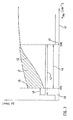
- FIG. 3 shows a boost / speed diagram of an internal combustion engine with turbocharger, the compressor part is equipped with an electric auxiliary drive.
- FIG. 3 shows that the self-sufficient, preferably designed as an electric auxiliary drive drive 24 below a critical speed range 44 of Internal combustion engine 10 is turned on at a time 40.
- This switch-on time 40 is in relation to the achievement of a lower critical speed value, laid in the present example about 1000 min -1 by a time lead 48 forward.
- the total switch-on duration 42 of the electric, self-sufficient auxiliary drive 24 is given by the switch-on duration 42, which extends from the switch-on time 40 of the electric auxiliary drive to its switch-off time 41 when an upper speed threshold of the critical speed range 44 of the internal combustion engine 10 is reached.
- FIG. 3 Example shown is the critical with regard to a sufficient boost pressure development speed range below a speed of 2000 min -1.
- a first boost pressure curve 45 is assigned. Due to the low exhaust gas volume flow in the partial load range of the internal combustion engine 10, the kinetic energy of the exhaust gas available for driving the turbine part 6 of the exhaust gas turbocharger 4 is insufficient to drive the compressor part 5, 23 of the exhaust gas turbocharger 4 in the same way as in the intake tract 2 of the internal combustion engine 10 can provide sufficient Ladedruclcerhöhung. It comes in this speed range, which corresponds to the critical speed range 44 of the internal combustion engine 10, to the occurrence of the so-called "turbo-hole".
- the drive of the compressor idler 23 is independent of the turbine runner 21 arranged on the supercharger shaft 7 by the switching on 40 of the independent auxiliary electric drive 24 via the drive shaft 25 through the clutch 26
- the compressor impeller 23 is cantilevered on the supercharger shaft 7 by the interposition of a freewheel 29.
- the speed of the turbine runner 21 is so high that the lock of the freewheel 29 engages within the compressor wheel 23, so that the electric auxiliary drive 24 via the clutch 26 can be separated from the compressor 23.
- the electric drive 24 accelerates only the compressor impeller 23.
- self-sufficient auxiliary drive 24 reaches the the turbine runner acting exhaust gas flow in the partial load range of the internal combustion engine 10, which passes through the exhaust duct 18, not to drive the compressor impeller 23 in the compressor part 5 of the exhaust gas turbocharger 4. Therefore, in this characterized by weak boost pressure operating range of the internal combustion engine, the compressor impeller 23 of the compressor part 5 of the exhaust gas turbocharger 4 is accelerated via the electric drive 24.
- the freewheel device 29 assumes its blocking function at its freewheeling unit, ie the compressor impeller 23 of the compressor part 5 of the exhaust gas turbocharger 4 takes over the drive of the compressor impeller 23, so that in the intake tract 2, ⁇ of the internal combustion engine 10, a sufficient increase in boost pressure due to the drive of the exhaust gas turbocharger 4 can again take place via the turbine runner 21 in the exhaust passage 18.
Landscapes
- Engineering & Computer Science (AREA)
- Chemical & Material Sciences (AREA)
- Combustion & Propulsion (AREA)
- Mechanical Engineering (AREA)
- General Engineering & Computer Science (AREA)
- Supercharger (AREA)
Claims (10)
- Turbocompresseur à gaz d'échappement (4) pour des moteurs à combustion interne (10), qui comprend une partie turbine (6) et une partie compresseur (5), lesquelles sont réceptionnées sur un arbre suralimenté (7) commun, laquelle partie de turbine (6) est disposée dans un canal de gaz d'échappement (18) du moteur à combustion interne (10) et laquelle partie compresseur (5) est logée dans la branche d'aspiration (2) du moteur à combustion interne (10), la partie compresseur (5) présentant un carter comprenant une entrée d'air et une sortie d'air, l'entrée d'air et la sortie d'air étant reliées entre elles par un canal d'écoulement et une compression d'air de suralimentation pouvant être obtenue par la rotation de la partie compresseur (5, 23), la partie compresseur (5, 23) du turbocompresseur à gaz d'échappement (4) pouvant être entraînée avec un entraînement supplémentaire (24) électrique autonome indépendamment de la charge du moteur à combustion interne (10), caractérisé en ce que l'entraînement supplémentaire (24) électrique autonome est enclenché avec une avance dans le temps (48) par rapport au moment où l'on obtient un seuil de régime inférieur d'une plage de régime critique (44) du moteur à combustion interne (10).
- Turbocompresseur à gaz d'échappement (4) selon la revendication 1, caractérisé en ce que la partie compresseur (5, 23) du dispositif suralimenté (4) est réceptionnée de façon rotative sur l'arbre suralimenté (7) par rapport au sens de rotation d'entraînement de l'entraînement (24) électrique.
- Turbocompresseur à gaz d'échappement (4) selon la revendication 2, caractérisé en ce que la partie compresseur (5, 23) du dispositif suralimenté (4) est réceptionnée au moyen d'un système de marche à vide (29) sur l'arbre suralimenté (7).
- Turbocompresseur à gaz d'échappement (4) selon la revendication 3, caractérisé en ce que le système de marche à vide (29) à l'intérieur d'une plage de régime critique (44) du moteur à combustion interne (10) autorise une rotation de la partie compresseur (5, 23) par rapport à l'arbre suralimenté (7) et la bloque au-dessus de la plage de régime critique (44) du moteur à combustion interne (10) de la rotation de la partie compresseur (5, 23) par rapport à l'arbre suralimenté (7).
- Turbocompresseur à gaz d'échappement (4) selon la revendication 4, caractérisé en ce que la plage de régime critique (44) du moteur à combustion interne (10), dans laquelle le système de marche à vide (29) autorise un déplacement relatif de la partie compresseur (23) par rapport à l'arbre suralimenté (7), est située au-dessous d'un régime du moteur à combustion interne (10) de 2000 t/min.
- Turbocompresseur à gaz d'échappement (4) selon la revendication 1, caractérisé en ce qu'un accouplement (26, 27, 28) est disposé entre l'arbre suralimenté (7) du dispositif suralimenté (4) et 1"entraînement supplémentaire (24) électrique autonome, lequel accouplement interrompt la liaison d'entraînement entre l'entraînement supplémentaire (24) électrique autonome et la partie compresseur (5, 23) du turbocompresseur à gaz d'échappement (4) lorsqu'on atteint une fonction de blocage pour supprimer la rotation de la partie compresseur (25) par rapport à l'arbre suralimenté (7) par le système de marche à vide (29) au-dessus de la plage de régime (44) critique.
- Turbocompresseur à gaz d'échappement (4) selon la revendication 6, caractérisé en ce que l'accouplement (26) présente une surface de couplage (27) côté entraînement et une surface de couplage (28) côté sortie, la surface de couplage (27) côté entraînement étant réalisée sur l'arbre d'entraînement (25) de l'entraînement supplémentaire (24) autonome électrique et la surface de couplage (28) côté sortie sur la roue à aubes de compresseur (23).
- Turbocompresseur à gaz d'échappement (4) selon la revendication 1, caractérisé en ce que le moment de déconnexion (41) de l'entraînement supplémentaire (25) électrique autonome coïncide avec le seuil de régime supérieur de la plage de régime critique (44) du moteur à combustion interne (10).
- Turbocompresseur à gaz d'échappement (4) selon la revendication 3, caractérisé en ce que le système de marche à vide (29) est réceptionné à l'intérieur d'un évidement (22) de la partie compresseur (5, 23) et comprend des éléments de marche à vide (30) qui sont réceptionnés entre deux disques de délimitation (31, 32).
- Turbocompresseur à gaz d'échappement (4) selon la revendication 6, caractérisé en ce que l'accouplement (26, 27, 28), agissant dans le sens de rotation d'entraînement de la partie de turbine (6) du dispositif suralimenté (7), interrompt la liaison d'entraînement entre l'arbre suralimenté (7) et l'entraînement supplémentaire (24) électrique lorsqu'on atteint un seuil de régime supérieur de la plage de régime critique (44).
Applications Claiming Priority (3)
| Application Number | Priority Date | Filing Date | Title |
|---|---|---|---|
| DE10229133A DE10229133A1 (de) | 2002-06-28 | 2002-06-28 | Ladeluft-Verdichter mit Elektrozusatzantrieb |
| DE10229133 | 2002-06-28 | ||
| PCT/DE2003/000503 WO2004003359A1 (fr) | 2002-06-28 | 2003-02-19 | Compresseur d'air de suralimentation a entrainement auxiliaire electrique |
Publications (2)
| Publication Number | Publication Date |
|---|---|
| EP1520089A1 EP1520089A1 (fr) | 2005-04-06 |
| EP1520089B1 true EP1520089B1 (fr) | 2010-07-28 |
Family
ID=29795968
Family Applications (1)
| Application Number | Title | Priority Date | Filing Date |
|---|---|---|---|
| EP03761396A Expired - Lifetime EP1520089B1 (fr) | 2002-06-28 | 2003-02-19 | Compresseur d'air de suralimentation a entrainement auxiliaire electrique |
Country Status (3)
| Country | Link |
|---|---|
| EP (1) | EP1520089B1 (fr) |
| DE (2) | DE10229133A1 (fr) |
| WO (1) | WO2004003359A1 (fr) |
Cited By (1)
| Publication number | Priority date | Publication date | Assignee | Title |
|---|---|---|---|---|
| DE102011013226A1 (de) | 2011-03-07 | 2012-09-13 | Guido Abt | Eingabe vom Einrichtung zur Verdichtung der Ansaugluft vor dem Luftfilter einer Brennkraftmaschine |
Families Citing this family (6)
| Publication number | Priority date | Publication date | Assignee | Title |
|---|---|---|---|---|
| DE102012019967B4 (de) | 2012-10-08 | 2014-04-24 | Iav Gmbh Ingenieurgesellschaft Auto Und Verkehr | Aufladeeinrichtung für Brennkraftmaschinen |
| DE102014210451A1 (de) * | 2014-06-03 | 2015-12-03 | Robert Bosch Gmbh | Turbolader mit elektrischer Maschine |
| DE102016003752B4 (de) | 2016-03-26 | 2022-06-09 | Audi Ag | Verfahren zum Betreiben einer Antriebseinrichtung eines Kraftfahrzeugs sowie entsprechende Antriebseinrichtung |
| DE102017216508A1 (de) | 2017-09-18 | 2019-03-21 | Robert Bosch Gmbh | Elektrische Maschine für den Antrieb eines Verdichters, einer Turbine oder einer Laderwelle eines Abgastorboladers einer Brennkraftmaschine |
| DE102017221103A1 (de) | 2017-11-24 | 2019-05-29 | Robert Bosch Gmbh | Elektrische Maschine für den Antrieb eines Verdichters, einer Turbine oder einer Laderwelle eines Abgasturboladers einer Brennkraftmaschine |
| FR3127030A1 (fr) * | 2021-09-14 | 2023-03-17 | Psa Automobiles Sa | Ensemble de suralimentation de gaz |
Family Cites Families (9)
| Publication number | Priority date | Publication date | Assignee | Title |
|---|---|---|---|---|
| DE3225389A1 (de) | 1982-07-07 | 1984-01-12 | Robert Bosch Gmbh, 7000 Stuttgart | Vorrichtung zum antrieb von hilfsaggregaten von kraftfahrzeugen |
| FR2619597B1 (fr) * | 1987-08-19 | 1990-01-19 | Lecoq Pierre | Perfectionnements a un turbo-compresseur de suralimentation d'un moteur a combustion interne |
| JPH03115739A (ja) * | 1989-09-28 | 1991-05-16 | Isuzu Motors Ltd | 回転電機付ターボチャージャ |
| DE9002114U1 (de) * | 1990-02-22 | 1991-03-21 | Menke, Bernard, 7500 Karlsruhe | Turbolader |
| ATE176947T1 (de) * | 1991-05-30 | 1999-03-15 | Edward M Halimi | Verfahren und vorrichtung zur überwindung der verzögerung eines turboladers |
| US5870894A (en) * | 1996-07-16 | 1999-02-16 | Turbodyne Systems, Inc. | Motor-assisted supercharging devices for internal combustion engines |
| DE19924918A1 (de) * | 1999-05-31 | 2000-12-07 | Volkswagen Ag | Abgasturbolader mit Energiespeicher und Energierückführung |
| DE10050161A1 (de) * | 2000-10-11 | 2002-04-18 | Daimler Chrysler Ag | Abgasturbolader für eine Brennkraftmaschine und Verfahren zum Betrieb eines Abgasturboladers |
| DE10061847A1 (de) * | 2000-12-12 | 2002-06-13 | Daimler Chrysler Ag | Abgasturbolader für eine Brennkraftmaschine und Verfahren zum Betrieb eines Abgasturboladers |
-
2002
- 2002-06-28 DE DE10229133A patent/DE10229133A1/de not_active Withdrawn
-
2003
- 2003-02-19 DE DE50312931T patent/DE50312931D1/de not_active Expired - Lifetime
- 2003-02-19 EP EP03761396A patent/EP1520089B1/fr not_active Expired - Lifetime
- 2003-02-19 WO PCT/DE2003/000503 patent/WO2004003359A1/fr not_active Ceased
Cited By (3)
| Publication number | Priority date | Publication date | Assignee | Title |
|---|---|---|---|---|
| DE102011013226A1 (de) | 2011-03-07 | 2012-09-13 | Guido Abt | Eingabe vom Einrichtung zur Verdichtung der Ansaugluft vor dem Luftfilter einer Brennkraftmaschine |
| WO2012119753A1 (fr) | 2011-03-07 | 2012-09-13 | Guido Abt | Dispositif servant à comprimer l'air d'admission avant le filtre à air d'un moteur à combustion interne |
| DE102011013226B4 (de) * | 2011-03-07 | 2012-10-18 | Guido Abt | Eingabe vom Einrichtung zur Verdichtung der Ansaugluft vor dem Luftfilter einer Brennkraftmaschine |
Also Published As
| Publication number | Publication date |
|---|---|
| DE10229133A1 (de) | 2004-02-05 |
| WO2004003359A1 (fr) | 2004-01-08 |
| DE50312931D1 (de) | 2010-09-09 |
| EP1520089A1 (fr) | 2005-04-06 |
Similar Documents
| Publication | Publication Date | Title |
|---|---|---|
| DE102007017777B4 (de) | Turboladeranordnung und turboaufladbare Brennkraftmaschine | |
| EP1723326B1 (fr) | Compresseur, moteur a combustion interne comportant un compresseur et procede de fonctionnement d'un moteur a combustion interne | |
| EP1844221B1 (fr) | Systeme de chargement a turbocompound, a compresseur raccordable | |
| EP3207231B1 (fr) | Dispositif de suralimentation pour un moteur à combustion interne et procédé de fonctionnement de dispositif de suralimentation | |
| EP2580444B1 (fr) | Compresseur pour moteur à combustion | |
| WO2000047879A1 (fr) | Procede pour actionner un moteur alternatif a compression prealable de l'air de combustion et moteur a pistons correspondant pour mettre ledit procede en oeuvre | |
| WO2016087125A1 (fr) | Dispositif de suralimentation pour moteur à combustion interne et procédé de fonctionnement du dispositif de suralimentation | |
| EP1388654B1 (fr) | Moteur à combustion interne suralimenté | |
| EP1546524B1 (fr) | Dispositif pour comprimer de l'air de combustion avec dispositif de derivation integre | |
| EP2530274A2 (fr) | Moteur à combustion interne chargé | |
| DE3205721A1 (de) | Aufgeladene brennkraftmaschine fuer fahrzeuge | |
| EP1520089B1 (fr) | Compresseur d'air de suralimentation a entrainement auxiliaire electrique | |
| DE102009042283A1 (de) | Turbocompoundsystem und Komponenten | |
| DE102011018570A1 (de) | Anordnung mit Brennkraftmaschine und Turbolader sowie Verfahren zum Betreiben eines Turboladers | |
| EP1504177B1 (fr) | Turbocompresseur a gaz d'echappement, a geometrie variable et a entrainement supplementaire pour un moteur a combustion interne | |
| DE10340142A1 (de) | Vorrichtung zur Verdichtung von Verbrennungsluft | |
| WO2016045829A1 (fr) | Système de suralimentation pour un moteur à combustion interne et procédé associé | |
| DE3142499A1 (de) | "turbolader-anordnung" | |
| EP0492272A1 (fr) | Moteur à combustion interne suralimenté | |
| WO2012119753A1 (fr) | Dispositif servant à comprimer l'air d'admission avant le filtre à air d'un moteur à combustion interne | |
| DE102017115349B4 (de) | Abgasturboladersystem für eine mehrreihige Brennkraftmaschine und Verfahren zum Betreiben eines Abgasturboladersystems | |
| DE8026375U1 (de) | Vorrichtung zur Vermeidung von Schmiermittelverlusten bei einem Abgasturbolader für Brennkraftmaschinen | |
| DE102015205910A1 (de) | Zweistufig aufladbare Brennkraftmaschine mit Abgasturbolader und Verfahren zum Betreiben einer derartigen Brennkraftmaschine | |
| EP1079082B1 (fr) | Procédé de commande d'un moteur suralimenté | |
| DE102018005374A1 (de) | Verbrennungskraftmaschine für ein Kraftfahrzeug, insbesondere für einen Kraftwagen |
Legal Events
| Date | Code | Title | Description |
|---|---|---|---|
| PUAI | Public reference made under article 153(3) epc to a published international application that has entered the european phase |
Free format text: ORIGINAL CODE: 0009012 |
|
| 17P | Request for examination filed |
Effective date: 20050128 |
|
| AK | Designated contracting states |
Kind code of ref document: A1 Designated state(s): AT BE BG CH CY CZ DE DK EE ES FI FR GB GR HU IE IT LI LU MC NL PT SE SI SK TR |
|
| RBV | Designated contracting states (corrected) |
Designated state(s): CH DE FR IT LI |
|
| RAP1 | Party data changed (applicant data changed or rights of an application transferred) |
Owner name: BOSCH MAHLE TURBO SYSTEMS GMBH & CO. KG |
|
| 17Q | First examination report despatched |
Effective date: 20090115 |
|
| GRAP | Despatch of communication of intention to grant a patent |
Free format text: ORIGINAL CODE: EPIDOSNIGR1 |
|
| GRAS | Grant fee paid |
Free format text: ORIGINAL CODE: EPIDOSNIGR3 |
|
| GRAA | (expected) grant |
Free format text: ORIGINAL CODE: 0009210 |
|
| AK | Designated contracting states |
Kind code of ref document: B1 Designated state(s): CH DE FR IT LI |
|
| REG | Reference to a national code |
Ref country code: CH Ref legal event code: EP |
|
| REF | Corresponds to: |
Ref document number: 50312931 Country of ref document: DE Date of ref document: 20100909 Kind code of ref document: P |
|
| PG25 | Lapsed in a contracting state [announced via postgrant information from national office to epo] |
Ref country code: IT Free format text: LAPSE BECAUSE OF FAILURE TO SUBMIT A TRANSLATION OF THE DESCRIPTION OR TO PAY THE FEE WITHIN THE PRESCRIBED TIME-LIMIT Effective date: 20100728 |
|
| PLBE | No opposition filed within time limit |
Free format text: ORIGINAL CODE: 0009261 |
|
| STAA | Information on the status of an ep patent application or granted ep patent |
Free format text: STATUS: NO OPPOSITION FILED WITHIN TIME LIMIT |
|
| 26N | No opposition filed |
Effective date: 20110429 |
|
| REG | Reference to a national code |
Ref country code: DE Ref legal event code: R097 Ref document number: 50312931 Country of ref document: DE Effective date: 20110429 |
|
| REG | Reference to a national code |
Ref country code: CH Ref legal event code: PL |
|
| PG25 | Lapsed in a contracting state [announced via postgrant information from national office to epo] |
Ref country code: CH Free format text: LAPSE BECAUSE OF NON-PAYMENT OF DUE FEES Effective date: 20110228 Ref country code: LI Free format text: LAPSE BECAUSE OF NON-PAYMENT OF DUE FEES Effective date: 20110228 |
|
| REG | Reference to a national code |
Ref country code: FR Ref legal event code: PLFP Year of fee payment: 13 |
|
| PGFP | Annual fee paid to national office [announced via postgrant information from national office to epo] |
Ref country code: FR Payment date: 20150227 Year of fee payment: 13 |
|
| PGFP | Annual fee paid to national office [announced via postgrant information from national office to epo] |
Ref country code: DE Payment date: 20150429 Year of fee payment: 13 |
|
| REG | Reference to a national code |
Ref country code: DE Ref legal event code: R119 Ref document number: 50312931 Country of ref document: DE |
|
| REG | Reference to a national code |
Ref country code: FR Ref legal event code: ST Effective date: 20161028 |
|
| PG25 | Lapsed in a contracting state [announced via postgrant information from national office to epo] |
Ref country code: DE Free format text: LAPSE BECAUSE OF NON-PAYMENT OF DUE FEES Effective date: 20160901 Ref country code: FR Free format text: LAPSE BECAUSE OF NON-PAYMENT OF DUE FEES Effective date: 20160229 |