EP1519798B1 - Method and casting roller plant for the semi-endless or endless rolling by casting of a metal in particular a steel strip which may be transversely separated as required after solidification - Google Patents
Method and casting roller plant for the semi-endless or endless rolling by casting of a metal in particular a steel strip which may be transversely separated as required after solidification Download PDFInfo
- Publication number
- EP1519798B1 EP1519798B1 EP03729965A EP03729965A EP1519798B1 EP 1519798 B1 EP1519798 B1 EP 1519798B1 EP 03729965 A EP03729965 A EP 03729965A EP 03729965 A EP03729965 A EP 03729965A EP 1519798 B1 EP1519798 B1 EP 1519798B1
- Authority
- EP
- European Patent Office
- Prior art keywords
- casting
- rolling
- roller
- speed
- hearth furnace
- Prior art date
- Legal status (The legal status is an assumption and is not a legal conclusion. Google has not performed a legal analysis and makes no representation as to the accuracy of the status listed.)
- Expired - Lifetime
Links
- 238000005096 rolling process Methods 0.000 title claims abstract description 99
- 238000005266 casting Methods 0.000 title claims abstract description 58
- 238000000034 method Methods 0.000 title claims abstract description 20
- 239000002184 metal Substances 0.000 title claims abstract description 7
- 229910000831 Steel Inorganic materials 0.000 title claims abstract description 6
- 239000010959 steel Substances 0.000 title claims abstract description 6
- 238000007711 solidification Methods 0.000 title claims abstract description 5
- 230000008023 solidification Effects 0.000 title claims abstract description 5
- 241001131688 Coracias garrulus Species 0.000 title claims 18
- 238000009749 continuous casting Methods 0.000 claims abstract description 21
- 238000010438 heat treatment Methods 0.000 claims abstract description 3
- 238000004519 manufacturing process Methods 0.000 claims description 6
- 238000005452 bending Methods 0.000 claims description 5
- 238000001816 cooling Methods 0.000 claims description 4
- 238000000926 separation method Methods 0.000 claims 3
- 238000011067 equilibration Methods 0.000 claims 1
- 238000003780 insertion Methods 0.000 claims 1
- 230000037431 insertion Effects 0.000 claims 1
- 238000005520 cutting process Methods 0.000 description 9
- 230000006978 adaptation Effects 0.000 description 2
- 230000003139 buffering effect Effects 0.000 description 2
- 238000004364 calculation method Methods 0.000 description 1
- 238000010276 construction Methods 0.000 description 1
- 238000011982 device technology Methods 0.000 description 1
- 238000009826 distribution Methods 0.000 description 1
- 230000000694 effects Effects 0.000 description 1
- 239000007788 liquid Substances 0.000 description 1
- 229910001338 liquidmetal Inorganic materials 0.000 description 1
- 238000007493 shaping process Methods 0.000 description 1
Images


Classifications
-
- B—PERFORMING OPERATIONS; TRANSPORTING
- B21—MECHANICAL METAL-WORKING WITHOUT ESSENTIALLY REMOVING MATERIAL; PUNCHING METAL
- B21B—ROLLING OF METAL
- B21B1/00—Metal-rolling methods or mills for making semi-finished products of solid or profiled cross-section; Sequence of operations in milling trains; Layout of rolling-mill plant, e.g. grouping of stands; Succession of passes or of sectional pass alternations
- B21B1/46—Metal-rolling methods or mills for making semi-finished products of solid or profiled cross-section; Sequence of operations in milling trains; Layout of rolling-mill plant, e.g. grouping of stands; Succession of passes or of sectional pass alternations for rolling metal immediately subsequent to continuous casting
-
- B—PERFORMING OPERATIONS; TRANSPORTING
- B21—MECHANICAL METAL-WORKING WITHOUT ESSENTIALLY REMOVING MATERIAL; PUNCHING METAL
- B21B—ROLLING OF METAL
- B21B13/00—Metal-rolling stands, i.e. an assembly composed of a stand frame, rolls, and accessories
- B21B13/22—Metal-rolling stands, i.e. an assembly composed of a stand frame, rolls, and accessories for rolling metal immediately subsequent to continuous casting, i.e. in-line rolling of steel
-
- B—PERFORMING OPERATIONS; TRANSPORTING
- B21—MECHANICAL METAL-WORKING WITHOUT ESSENTIALLY REMOVING MATERIAL; PUNCHING METAL
- B21B—ROLLING OF METAL
- B21B1/00—Metal-rolling methods or mills for making semi-finished products of solid or profiled cross-section; Sequence of operations in milling trains; Layout of rolling-mill plant, e.g. grouping of stands; Succession of passes or of sectional pass alternations
- B21B1/22—Metal-rolling methods or mills for making semi-finished products of solid or profiled cross-section; Sequence of operations in milling trains; Layout of rolling-mill plant, e.g. grouping of stands; Succession of passes or of sectional pass alternations for rolling plates, strips, bands or sheets of indefinite length
- B21B1/24—Metal-rolling methods or mills for making semi-finished products of solid or profiled cross-section; Sequence of operations in milling trains; Layout of rolling-mill plant, e.g. grouping of stands; Succession of passes or of sectional pass alternations for rolling plates, strips, bands or sheets of indefinite length in a continuous or semi-continuous process
- B21B1/26—Metal-rolling methods or mills for making semi-finished products of solid or profiled cross-section; Sequence of operations in milling trains; Layout of rolling-mill plant, e.g. grouping of stands; Succession of passes or of sectional pass alternations for rolling plates, strips, bands or sheets of indefinite length in a continuous or semi-continuous process by hot-rolling, e.g. Steckel hot mill
-
- B—PERFORMING OPERATIONS; TRANSPORTING
- B21—MECHANICAL METAL-WORKING WITHOUT ESSENTIALLY REMOVING MATERIAL; PUNCHING METAL
- B21B—ROLLING OF METAL
- B21B1/00—Metal-rolling methods or mills for making semi-finished products of solid or profiled cross-section; Sequence of operations in milling trains; Layout of rolling-mill plant, e.g. grouping of stands; Succession of passes or of sectional pass alternations
- B21B1/46—Metal-rolling methods or mills for making semi-finished products of solid or profiled cross-section; Sequence of operations in milling trains; Layout of rolling-mill plant, e.g. grouping of stands; Succession of passes or of sectional pass alternations for rolling metal immediately subsequent to continuous casting
- B21B1/466—Metal-rolling methods or mills for making semi-finished products of solid or profiled cross-section; Sequence of operations in milling trains; Layout of rolling-mill plant, e.g. grouping of stands; Succession of passes or of sectional pass alternations for rolling metal immediately subsequent to continuous casting in a non-continuous process, i.e. the cast being cut before rolling
-
- B—PERFORMING OPERATIONS; TRANSPORTING
- B21—MECHANICAL METAL-WORKING WITHOUT ESSENTIALLY REMOVING MATERIAL; PUNCHING METAL
- B21B—ROLLING OF METAL
- B21B31/00—Rolling stand structures; Mounting, adjusting, or interchanging rolls, roll mountings, or stand frames
- B21B31/08—Interchanging rolls, roll mountings, or stand frames, e.g. using C-hooks; Replacing roll chocks on roll shafts
- B21B31/10—Interchanging rolls, roll mountings, or stand frames, e.g. using C-hooks; Replacing roll chocks on roll shafts by horizontally displacing, i.e. horizontal roll changing
-
- B—PERFORMING OPERATIONS; TRANSPORTING
- B21—MECHANICAL METAL-WORKING WITHOUT ESSENTIALLY REMOVING MATERIAL; PUNCHING METAL
- B21B—ROLLING OF METAL
- B21B37/00—Control devices or methods specially adapted for metal-rolling mills or the work produced thereby
- B21B37/005—Control of time interval or spacing between workpieces
-
- B—PERFORMING OPERATIONS; TRANSPORTING
- B21—MECHANICAL METAL-WORKING WITHOUT ESSENTIALLY REMOVING MATERIAL; PUNCHING METAL
- B21B—ROLLING OF METAL
- B21B45/00—Devices for surface or other treatment of work, specially combined with or arranged in, or specially adapted for use in connection with, metal-rolling mills
- B21B45/004—Heating the product
-
- Y—GENERAL TAGGING OF NEW TECHNOLOGICAL DEVELOPMENTS; GENERAL TAGGING OF CROSS-SECTIONAL TECHNOLOGIES SPANNING OVER SEVERAL SECTIONS OF THE IPC; TECHNICAL SUBJECTS COVERED BY FORMER USPC CROSS-REFERENCE ART COLLECTIONS [XRACs] AND DIGESTS
- Y10—TECHNICAL SUBJECTS COVERED BY FORMER USPC
- Y10T—TECHNICAL SUBJECTS COVERED BY FORMER US CLASSIFICATION
- Y10T29/00—Metal working
- Y10T29/49—Method of mechanical manufacture
- Y10T29/4998—Combined manufacture including applying or shaping of fluent material
- Y10T29/49988—Metal casting
- Y10T29/49989—Followed by cutting or removing material
-
- Y—GENERAL TAGGING OF NEW TECHNOLOGICAL DEVELOPMENTS; GENERAL TAGGING OF CROSS-SECTIONAL TECHNOLOGIES SPANNING OVER SEVERAL SECTIONS OF THE IPC; TECHNICAL SUBJECTS COVERED BY FORMER USPC CROSS-REFERENCE ART COLLECTIONS [XRACs] AND DIGESTS
- Y10—TECHNICAL SUBJECTS COVERED BY FORMER USPC
- Y10T—TECHNICAL SUBJECTS COVERED BY FORMER US CLASSIFICATION
- Y10T29/00—Metal working
- Y10T29/49—Method of mechanical manufacture
- Y10T29/4998—Combined manufacture including applying or shaping of fluent material
- Y10T29/49988—Metal casting
- Y10T29/49991—Combined with rolling
Definitions
- the invention relates to a method and a casting rolling mill for semi-endless or continuous rolling by casting a metal, in particular a Stahlfstrangs which is transversely divided if necessary after solidification, the G manstrang part lengths are guided in a roller hearth furnace for heating and uniform to rolling temperature, and the part-length rolling temperature for rolling in a rolling mill are introduced, wherein the continuous casting is continued during the rolling operation without interruption.
- a metal in particular a Stahlfstrangs which is transversely divided if necessary after solidification
- Such a method is known from EP 0 264 459 B1.
- the G manstrang partial lengths are stored in the tunnel furnace under cross-transport.
- the G manstrang part lengths are stored over a period corresponding to a multiple, eg four times, their casting time.
- the method is practiced such that the rolling of each casting strand part length is carried out in a unit of time, which corresponds to only a fraction, eg one-fifth of its casting time, and to the effect that the rolling carried discontinuous and thereby the rolling process in each case over a tent area , which corresponds to the difference between a casting time and a rolling, is interrupted with a pause time.
- This method is strictly based on continuous casting and is not adapted to the rolling process.
- European patent application EP 0 853 987 A2 discloses a system for producing a strip, a pre-strip or a slab.
- the disclosed there invention is based on the object to create a system, which enables high-quality production of the thinnest possible bands, with a very high operational flexibility is given.
- the continuous casting should be able to continue in the case of a fault at a downstream of the continuous mold deformation stage.
- US Pat. No. 5,396,695 discloses a method and a device according to the preambles of claims 1 and 9, respectively, for controlling a period of time between the continuous casting of metal strands and their entry into a rolling stand.
- the invention disclosed there is based on the finding that it takes longer to cast a thicker slab than a thinner slab of the same length. It can therefore be controlled by adjusting or changing the cross section of the cast strand, the speed at which the cast strand emerges between pinch rollers, at the same casting rate. In particular, it is in this way, i. by increasing the cross-section of the cast strand, it is possible to gain time for a roll change at the same flow rate.
- the object of the invention is to provide an alternative method and an alternative device, in which it is also possible to set time, e.g. to win for a roll change within a rolling mill.
- This object is achieved according to the method claimed in claim 1, characterized in that between rolling campaigns within a casting sequence after the cross-cutting the final rolling thickness and / or the drawing speed of the rolling mill is increased.
- the semi-endless rolling and the endless rolling are adjusted to the conditions of rolling, and a buffer time for the inevitable roll change is provided.
- the larger rolling stock lengths resulting from the semi- or continuous rolling are taken into account in that several coils are produced from one multiple length.
- the buffer time for the roll change can still be influenced by reducing the casting speed as a function of the drawing speed of the rolling train and / or the roll change time, including the calibration time and / or the buffer length of the roller hearth furnace and / or the final rolling thickness after the transverse cutting.
- the buffer length of the roller hearth furnace is tuned to at least one roller level.
- An embodiment is further that a combination of an adaptation of the casting speed and the final rolling thickness is used to optimize the production capacity.
- Another buffering time can be achieved by maximizing the final rolling thickness by a factor of 2 and lowering the casting speed to a minimum of 30%.
- the method can be applied according to a practical example such that after the cross-cutting the casting speed is reduced and / or the feed speed of the rolling train and / or the final roll thickness are increased, after the completion of rolling the worn rolls of the rolling train are changed and after the roll change the Casting speed is increased to the feed speed of the rolling mill.
- the strand guide can also be designed so that multiple lengths can be inserted at a single height level from the outlet of the continuous casting machine through the roller conveyor of the roller hearth furnace into the rolling mill.
- a casting rolling mill is shown in side view, consisting of a continuous casting machine 1, in which a cast strand 1a is produced, a roller hearth furnace 2 and a rolling mill 3 with the associated ancillary equipment.
- a distributor vessel 4 is fed from a ladle (not shown) to which a continuous casting mold 5, a support roll stand 6 with a bending unit 7 and a straightening machine 8 are arranged downstream.
- a cross-cutting device 10 At the output 9 is a cross-cutting device 10 and behind this (as an alternative in Fig. 5) a pivotable roller conveyor 11 for the input 12a of the roller hearth furnace 2 is arranged.
- a pivotable roller conveyor 13 At its output 12b are again a pivotable roller conveyor 13 and a cross-cutting device 14.
- the basic embodiment in Fig. 1 operates without the pivotable roller conveyors 11, 13th
- the rolling train 3 begins after the cross-cutting device 14 with a descaling device 15. Then follows the rolling mill 3 with about five to seven rolling stands. Behind the rolling stands, a cooling section 17 and this following two coiler 18 are provided after a separator 16.
- the method is used for semi-continuous rolling or continuous rolling by casting of liquid metal, in particular of liquid steel, to form a cast strand 1 a, which after solidification in the cross-cutting device 10 in G confusestrang part lengths 20 is transported in the roller hearth furnace 2.
- the respective G fauxstrang part length 20 is heated in the roller hearth furnace 2, evened out in temperature and brought to rolling temperature for rolling in the rolling mill 3. During this time, the continuous casting continues without interruption.
- the casting speed V c is lowered for a roll change such that between the end of rolling a previous multiple length 21 and the piercing of a new part length 20 or multiple length 21 in the rolling train 3 sufficient buffer time for the roll change is available. From the multiple length 21 more coils 22 can be wound.
- the casting speed V c for example, depending on the feed speed V w of the rolling train 3 and / or the respective roller change time including a calibration time and / or the buffer length 23 of the roller hearth furnace 2 and / or the final rolling thickness reduced after the cutting.
- the buffer length 23 of the roller hearth furnace 2 can be matched to at least one roller plane 24 (see Fig. 1).
- the casting speed V c is set equal to or less than the drawing speed V w in the rolling mill 3. As shown in FIG. Once the roller hearth furnace 2 is charged, the speed V c can be raised again to the pull-in speed V w , as shown in FIG. 2B.
- Fig. 3A the endless rolling is shown.
- the casting strand 1a is guided and rolled at a casting speed V c equal to the drawing speed V w in the first rolling stand, then cooled, wound and cut in the separating device 16.
- the cast strand 1a can, as shown in Fig. 3B, with reduced casting speed V c are cast and the separated G manstrang part length 20 is rolled at the pull speed V w and wound.
- the roll change is shown in Fig. 4A.
- the casting speed V c is 6.67 m / min according to the above calculation and is accordingly lower than the pull-in speed V w .
- Fig. 4B the casting speed V c is increased again to the pull-in speed V w .
- the final rolling thickness and / or the drawing speed V w of the rolling train 3 can be increased after the transverse cutting.
- the final rolling thickness can be increased by a maximum of 2.5 times.
- Another option is to maximize the finish roll thickness by a factor of 2 and lower the casting speed to a minimum of 30%.
- the casting speed V c is reduced, and / or the drawing speed V w of the rolling mill 3 and / or the final roll thickness are increased, after the completion of rolling the worn rolls 3a of the rolling mill 3 are changed and after the roll change, the casting speed V c is increased to the drawing speed V w of the rolling train 3.
- the casting and rolling mill for semi-endless or continuous rolling a cast metal or steel strand which is divisible as cast strand 1a in the solidified state if necessary in G manstrang part 20 and the G manstrang part lengths 20 are kept warm in a roller hearth furnace 2 and heated to rolling temperature and homogenized and subsequently introduced into a rolling mill 3 presupposes that continuous casting takes place on the continuous casting machine 1.
- a cross-dividing device 14 below a descaling device 15 are provided on it first rolling mill follows and behind the rolling mill 3, the separator 16, cooling section 17 and coiler 18 are arranged.
- the inlet and outlet side roller conveyors 11, 13 have bending and / or straightening units 7, 8, which can be set or set up on the respective roller plane 24.
- the pivotable roller conveyors 11, 13 are provided at the entrance 12a and at the exit 12b of the roller hearth furnace 2 with at least two roller levels 24, each with a bending and / or straightening unit 7, 8 (see Fig. 5).
Abstract
Description
Die Erfindung betrifft ein Verfahren und eine Gießwalzanlage zum Semi-Endloswalzen oder Endloswalzen durch Gießen eines Metall-, insbesondere eines Stahlfstrangs, der nach dem Erstarren bei Bedarf quergeteilt wird, die Gießstrang-Teillängen in einen Rollenherdofen zum Aufheizen und Vergleichmäßigen auf Walztemperatur geführt werden, und die Teillängen mit Walztemperatur zum Auswalzen in eine Walzstraße eingeführt werden, wobei das Stranggießen während des Walzbetriebs ohne Unterbrechung fortgesetzt wird.The invention relates to a method and a casting rolling mill for semi-endless or continuous rolling by casting a metal, in particular a Stahlfstrangs which is transversely divided if necessary after solidification, the Gießstrang part lengths are guided in a roller hearth furnace for heating and uniform to rolling temperature, and the part-length rolling temperature for rolling in a rolling mill are introduced, wherein the continuous casting is continued during the rolling operation without interruption.
Ein derartiges Verfahren ist aus der EP 0 264 459 B1 bekannt. Bei diesem Verfahren werden die Gießstrang-Teillängen im Tunnelofen unter Quertransport gespeichert.
Die Gießstrang-Teillängen werden über einen Zeitraum gespeichert, der einem Mehrfachen, z.B. dem Vierfachen, ihrer Gießzeit entspricht. Weiter wird das Verfahren derart ausgeübt, dass die Walzung jeder einzelnen Gießstrang-Teillänge aber in einer Zeiteinheit durchgeführt wird, die nur einem Bruchteil, z.B. einem Fünftel seiner Gießzeit entspricht, und dahingehend, dass die Walzung diskontinulerlich durchgeführt und dabei der Walzvorgang jeweils über einen Zeltraum, der der Differenz zwischen einer Gießzeit und einer Walzung entspricht, mit einer Pausenzeit unterbrochen wird. Dieses Verfahren richtet sich streng nach dem Stranggießen und ist nicht auf das Walzverfahren abgestimmt.Such a method is known from EP 0 264 459 B1. In this process, the Gießstrang partial lengths are stored in the tunnel furnace under cross-transport.
The Gießstrang part lengths are stored over a period corresponding to a multiple, eg four times, their casting time. Further, the method is practiced such that the rolling of each casting strand part length is carried out in a unit of time, which corresponds to only a fraction, eg one-fifth of its casting time, and to the effect that the rolling carried discontinuous and thereby the rolling process in each case over a tent area , which corresponds to the difference between a casting time and a rolling, is interrupted with a pause time. This method is strictly based on continuous casting and is not adapted to the rolling process.
Aus der europäischen Patentanmeldung EP 0 853 987 A2 ist eine Anlage zum Herstellen eines Bandes, eines Vorstreifens oder einer Bramme bekannt. Der dort offenbarten Erfindung liegt die Aufgabe zugrunde, eine Anlage zu schaffen, welche bei hoher Produktqualität die Herstellung möglichst dünner Bänder ermöglicht, wobei eine sehr hohe Betriebsflexibilität gegeben ist. Insbesondere soll das Stranggießen im Fall einer Störung an einer der Durchlaufkokille nachgeordneten Verformungsstufe fortgesetzt werden können. Zur Lösung dieser Aufgabe wird vorgeschlagen, die unterschiedlichen der Kokille nachgeschalteten Verformungsstufen aktivierbar bzw. deaktivierbar zu machen, wobei zur Herstellung eines möglichst dünnen Bandes sämtliche Verformungsstufen in Summe aktiviert werden sollen, wobei zur Herstellung eines Bandes mit etwas größerer Dicke nur die zweite und dritte Verformungsstufe einzeln oder in Summe aktiviert werden sollen und wobei zur Herstellung einer unverformten Bramme alle drei Verformungsstufen deaktiviert werden sollen.European patent application EP 0 853 987 A2 discloses a system for producing a strip, a pre-strip or a slab. The disclosed there invention is based on the object to create a system, which enables high-quality production of the thinnest possible bands, with a very high operational flexibility is given. In particular, the continuous casting should be able to continue in the case of a fault at a downstream of the continuous mold deformation stage. To solve this problem, it is proposed to make the various shaping stages downstream of the mold activatable or deactivatable, wherein for the production of a very thin strip all deformation stages should be activated in total, wherein for the production of a strip with a slightly greater thickness, only the second and third deformation stage should be activated individually or in total and to disable all three deformation stages to produce an undeformed slab.
Weiterhin ist aus der US Patentschrift US 5,396,695 ein Verfahren bzw. eine Vorrichtung nach den Oberbegriffen der Ansprüche 1 bzw. 9 zum Steuern einer Zeitdauer zwischen dem kontinuierlichen Gießen von Metallsträngen und deren Eintritt in ein Walzgerüst bekannt. Der dort offenbarten Erfindung liegt die Erkenntnis zugrunde, dass es länger dauert, eine dickere Bramme zu gießen als eine dünnere Bramme bei gleicher Länge. Es kann deshalb durch eine Anpassung bzw. Veränderung des Querschnitts des gegossenen Strangs die Geschwindigkeit gesteuert werden, mit welcher der Gießstrang zwischen Quetschrollen hervortritt, bei gleicher Gießrate. Insbesondere ist es auf diese Weise, d.h. durch Vergrößern des Querschnitts des Gießstrangs, möglich, bei gleicher Gleßrate Zeit für einen Walzenwechsel zu gewinnen.Furthermore, US Pat. No. 5,396,695 discloses a method and a device according to the preambles of
Ausgehend von diesem Stand der Technik liegt der Erfindung die Aufgabe zugrunde, ein alternatives Verfahren und eine alternative Vorrichtung bereit zu stellen, bei denen es ebenfalls möglich ist, Zeit z.B. für einen Walzenwechsel innerhalb einer Walzstraße zu gewinnen.Starting from this prior art, the object of the invention is to provide an alternative method and an alternative device, in which it is also possible to set time, e.g. to win for a roll change within a rolling mill.
Diese Aufgabe wird gemäß dem in dem Patentanspruch 1 beanspruchten Verfahren dadurch gelöst, dass zwischen Walzkampagnen innerhalb einer Gießsequenz nach dem Querteilen die Endwalzdicke und / oder die Einzugsgeschwindigkeit des Walzwerks erhöht wird.This object is achieved according to the method claimed in claim 1, characterized in that between rolling campaigns within a casting sequence after the cross-cutting the final rolling thickness and / or the drawing speed of the rolling mill is increased.
Dadurch wird das Semi-Endloswalzen und das Endloswalzen auf die Verhältnisse des Walzens angepasst und es wird eine Pufferzeit für den unvermeidlichen Walzenwechsel geschaffen.Thereby, the semi-endless rolling and the endless rolling are adjusted to the conditions of rolling, and a buffer time for the inevitable roll change is provided.
Die durch das Semi- oder Endloswalzen entstehenden größeren Walzgut-Längen werden dabei dadurch berücksichtigt, dass aus einer Mehrfachlänge mehrere Coils erzeugt werden.The larger rolling stock lengths resulting from the semi- or continuous rolling are taken into account in that several coils are produced from one multiple length.
Die Pufferzeit für den Walzenwechsel kann noch dadurch beeinflusst werden, dass die Gießgeschwindigkeit in Abhängigkeit der Einzugsgeschwindigkeit der Walzstraße und / oder der Walzenwechselzeit einschließlich der Kalibrierzeit und /oder der Pufferlänge des Rollenherdofens und / oder der Endwalzdicke nach dem Querteilen reduziert wird.The buffer time for the roll change can still be influenced by reducing the casting speed as a function of the drawing speed of the rolling train and / or the roll change time, including the calibration time and / or the buffer length of the roller hearth furnace and / or the final rolling thickness after the transverse cutting.
Nach einem anderen Merkmal wird vorgeschlagen, dass die Pufferlänge des Rollenherdofens zumindest auf eine Rollenebene abgestimmt wird.According to another feature, it is proposed that the buffer length of the roller hearth furnace is tuned to at least one roller level.
Um die gewünschte Pufferzeit zu erreichen ist ferner vorteilhaft, dass die Gießgeschwindigkeit Vc, die der Einzugsgeschwindigkeit Vw des Walzwerkes entspricht, gleich oder größer nach der folgenden Formel reduziert wird: 
wobei bedeuten:
- ΔV =
- Gießgeschwindigkeitsreduzierung
- Vw =
- Einzugsgeschwindigkeit des Walzwerks
- Δt =
- Walzenwechselzeit und
- L =
- Länge des Tunnelofens.
where:
- ΔV =
- Gießgeschwindigkeitsreduzierung
- V w =
- Feed speed of the rolling mill
- Δt =
- Roll change time and
- L =
- Length of the tunnel kiln.
Eine Ausgestaltung besteht ferner darin, dass eine Kombination aus einer Anpassung der Gießgeschwindigkeit und der Endwalzdicke zur Optimierung der Produktionsleistung angewendet wird.An embodiment is further that a combination of an adaptation of the casting speed and the final rolling thickness is used to optimize the production capacity.
Dabei ist außerdem von Vorteil, wenn die Endwalzdicke maximal um den Faktor 2,5 erhöht wird.It is also advantageous if the Endwalzdicke is increased by a maximum of a factor of 2.5.
Eine andere Pufferzeit kann dahingehend erzielt werden, indem die Endwalzdicke maximal um den Faktor 2 erhöht und die Gießgeschwindigkeit auf minimal 30% abgesenkt wird.Another buffering time can be achieved by maximizing the final rolling thickness by a factor of 2 and lowering the casting speed to a minimum of 30%.
Das Verfahren kann nach einem praktischen Beispiel derart angewendet werden, dass nach dem Querteilen die Gießgeschwindigkeit reduziert wird und /oder die Einzugsgeschwindigkeit der Walzstraße und / oder die Endwalzdicke erhöht werden, nach Beenden des Walzens die verschlissenen Walzen der Walzstraße gewechselt werden und nach erfolgtem Walzenwechsel die Gießgeschwindigkeit auf die Einzugsgeschwindigkeit der Walzstraße gesteigert wird.The method can be applied according to a practical example such that after the cross-cutting the casting speed is reduced and / or the feed speed of the rolling train and / or the final roll thickness are increased, after the completion of rolling the worn rolls of the rolling train are changed and after the roll change the Casting speed is increased to the feed speed of the rolling mill.
Die oben genannte Aufgabe der Erfindung wird weiterhin durch den in Patentanspruch 9 beanspruchten Gegenstand gelöst.The above object of the invention is further achieved by the subject-matter claimed in
Die Strangführung kann auch dahingehend ausgebildet sein, dass Mehrfachlängen auf einem einzigen Höhen-Niveau von dem Ausgang der Stranggießmaschine durch die Rollenbahn des Rollenherdofens bis in das Walzwerk einführbar sind.The strand guide can also be designed so that multiple lengths can be inserted at a single height level from the outlet of the continuous casting machine through the roller conveyor of the roller hearth furnace into the rolling mill.
In der Zeichnung sind Ausführungsbeispiele der Erfindung dargestellt, die nachstehend verfahrens- und vorrichtungstechnisch näher erläutert werden.In the drawings, embodiments of the invention are shown, which are explained below procedural and device technology closer.
Es zeigen:
- Fig. 1
- die Gießwalzanlage mit einem Rollenherdofen und einer Rollenebene in Seitenansicht,
- Fig. 2A
- eine Seiten-Teilansicht mit einem Gießstrang, wobei die Gießgeschwindigkeit gleich oder kleiner der Walzgeschwindigkeit ist,
- Fig. 2B
- dieselbe Ansicht bei auf Walzgeschwindigkeit erhöhter Transportgeschwindigkeit einer Gießstrang-Teillänge,
- Fig. 3A
- das Endlos-Gießen und -Walzen bei gleicher Gieß- und Walzgeschwindigkeit und mit zwei Haspelanlagen,
- Fig. 3B
- das Endlos-Gießen und -Walzen mit den zwei Haspelanlagen,
- Fig. 4A
- die Situation beim Walzenwechsel und reduzierter Gießgeschwindigkeit,
- Fig.4B
- die Situation nach beendetem Walzenwechsel und gesteigerter Gießgeschwindigkeit und
- Fig. 5
- die Gießwalzanlage in der Seitenansicht wie Fig. 1 für eine alternative Ausführungsform.
- Fig. 1
- the cast rolling mill with a roller hearth furnace and a roller level in side view,
- Fig. 2A
- a partial side view with a cast strand, wherein the casting speed is equal to or less than the rolling speed,
- Fig. 2B
- the same view when the transport speed of a cast strand partial length is increased at rolling speed,
- Fig. 3A
- Continuous casting and rolling at the same casting and rolling speed and with two coiler units,
- Fig. 3B
- the endless casting and rolling with the two coiler lines,
- Fig. 4A
- the situation during roll change and reduced casting speed,
- 4B
- the situation after completion of roll change and increased casting speed and
- Fig. 5
- the casting rolling mill in the side view as Fig. 1 for an alternative embodiment.
In Fig.1 ist eine Gießwalzanlage in Seitenansicht dargestellt, bestehend aus einer Stranggießmaschine 1, in der ein Gießstrang 1a erzeugt wird, einem Rollenherdofen 2 und einer Walzstraße 3 mit den zugehörigen Nebeneinrichtungen.In Figure 1, a casting rolling mill is shown in side view, consisting of a continuous casting machine 1, in which a cast strand 1a is produced, a
In der Stranggießmaschine 1 wird aus einer (nicht gezeichneten) Gießpfanne ein Verteilergefäß 4 gespeist, dem eine Stranggießkokille 5, ein Stützrollengerüst 6 mit einer Biegeeinheit 7 und eine Richtmaschine 8 nachgeordnet sind. Am Ausgang 9 ist eine Querteileinrichtung 10 und hinter dieser (als Alternative in Fig. 5) eine schwenkbare Rollenbahn 11 für den Eingang 12a des Rollenherdofens 2 angeordnet. An dessen Ausgang 12b befinden sich wiederum eine schwenkbare Rollenbahn 13 und eine Querteileinrichtung 14. Die Grundausführungsform in Fig. 1 arbeitet ohne die schwenkbaren Rollenbahnen 11, 13.In the continuous casting machine 1, a
Die Walzstraße 3 beginnt nach der Querteileinrichtung 14 mit einer Entzunderungseinrichtung 15. Darauf folgt die Walzstraße 3 mit etwa fünf bis sieben Walzgerüsten. Hinter den Walzgerüsten sind nach einer Trenneinrichtung 16 eine Kühlstrecke 17 und dieser folgend zwei Haspelanlagen 18 vorgesehen.The rolling
Das Verfahren dient dem Semi-Endloswalzen oder dem Endloswalzen durch Gießen von flüssigem Metall, insbesondere von flüssigem Stahl, zu einem Gießstrang 1 a, der nach dem Erstarren in der Querteileinrichtung 10 in Gießstrang-Teillängen 20 in den Rollenherdofen 2 befördert wird. Die jeweilige Gießstrang-Teillänge 20 wird im Rollenherdofen 2 aufgeheizt, in der Temperatur vergleichmäßigt und auf Walztemperatur zum Auswalzen in der Walzstraße 3 gebracht. Während dieser Zeit wird das Stranggießen ohne Unterbrechung weiter geführt.The method is used for semi-continuous rolling or continuous rolling by casting of liquid metal, in particular of liquid steel, to form a cast strand 1 a, which after solidification in the
Für den Fall, dass die Walzen 3a verschlissen sind, wird für einen Walzenwechsel die Gießgeschwindigkeit Vc derart abgesenkt, dass zwischen dem Ende des Walzens einer vorhergehenden Mehrfachlänge 21 und dem Anstechen einer neuen Teillänge 20 oder Mehrfachlänge 21 in der Walzstraße 3 eine ausreichende Pufferzeit für den Walzenwechsel zur Verfügung steht. Aus der Mehrfachlänge 21 können mehrere Coils 22 gewickelt werden.In the event that the
Die Gießgeschwindigkeit Vc wird z.B. in Abhängigkeit der Einzugsgeschwindigkeit
Vw der Walzstraße 3 und / oder der jeweiligen Walzenwechselzeit einschließlich einer Kalibrierzeit und / oder der Pufferlänge 23 des Rollenherdofens 2 und / oder der Endwalzdicke nach dem Querteilen reduziert. Die Pufferlänge 23 des Rollenherdofens 2 kann zumindest auf eine Rollenebene 24 abgestimmt werden (vgl. Fig. 1).The casting speed V c , for example, depending on the feed speed
V w of the rolling
In Fig. 2A wird die Gießgeschwindigkeit Vc gleich oder kleiner als die Einzugsgeschwindigkeit Vw in die Walzstraße 3 eingestellt. Sobald der Rollenherdofen 2 beschickt ist, kann die Geschwindigkeit Vc auf Einzugsgeschwindigkeit Vw wieder angehoben werden, wie in Fig. 2B gezeigt ist.In FIG. 2A, the casting speed V c is set equal to or less than the drawing speed V w in the rolling
In Fig. 3A ist das Endloswalzen gezeigt. Der Gießstrang 1a wird mit Gießgeschwindigkeit V c, die gleich der Einzugsgeschwindigkeit V w in das erste Walzgerüst ist, geführt und gewalzt, dann gekühlt, gewickelt und in der Trenneinrichtung 16 geschnitten. Nach einer Querteilung in der Querteileinrichtung 10 kann der Gießstrang 1a, wie in Fig. 3B gezeigt ist, mit reduzierter Gießgeschwindigkeit Vc gegossen werden und die abgetrennte Gießstrang-Teillänge 20 wird mit Einzugsgeschwindigkeit Vw gewalzt und gewickelt.In Fig. 3A, the endless rolling is shown. The casting strand 1a is guided and rolled at a casting speed V c equal to the drawing speed V w in the first rolling stand, then cooled, wound and cut in the separating
Die Gießgeschwindigkeit Vc wird gleich oder größer nach der folgenden Formel reduziert: 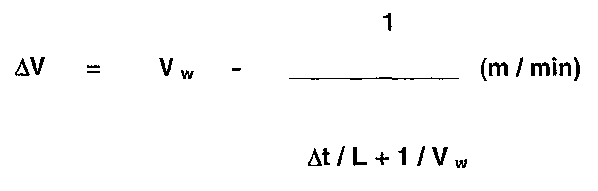
wobei bedeuten:
- ΔV =
- Gießgeschwindigkeitsreduzierung (m / min)
- Vw =
- Einzugsgeschwindigkeit des Walzwerks (m / min)
- Δt =
- Walzenwechselzeit (min)
- L =
- Länge des Tunnelofens (m).
where:
- ΔV =
- Casting speed reduction (m / min)
- V w =
- Feed speed of the rolling mill (m / min)
- Δt =
- Roll change time (min)
- L =
- Length of tunnel kiln (m).
Bei einer Einzugsgeschwindigkeit Vw = 10 m / min, einer Walzenwechselzeit Δt = 10 min und einer Rollenherdofen-Länge L = 200 m muss die Gießgeschwindigkeit Vc um mindestens 3,33 m/min reduziert werden. 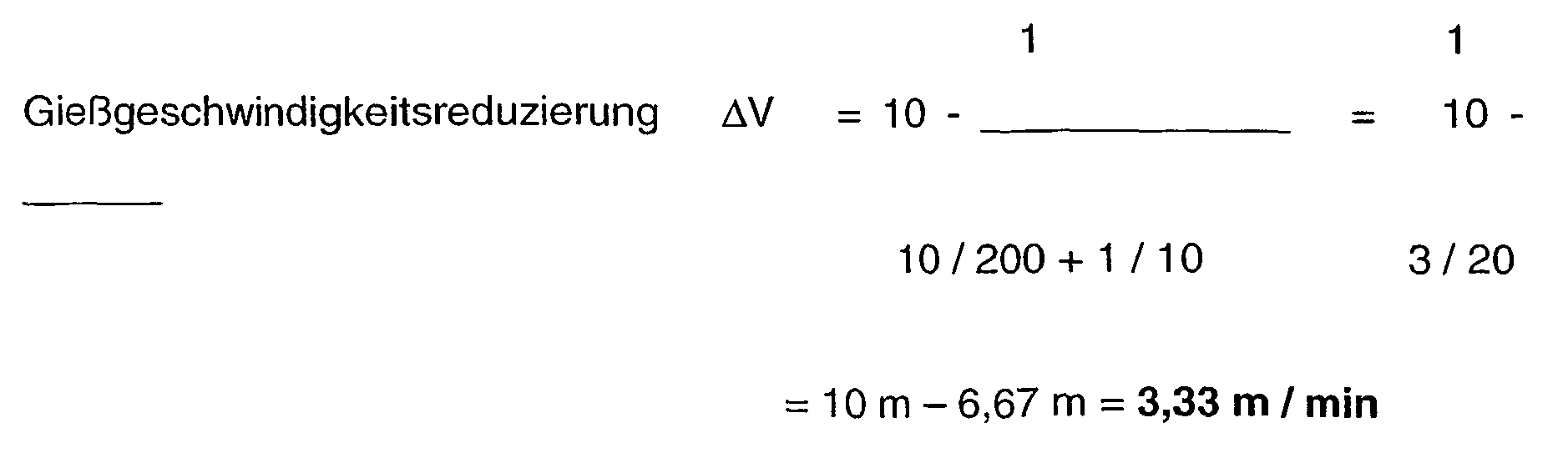
Der Walzenwechsel ist in Fig. 4A dargestellt. Die Gießgeschwindigkeit Vc beträgt nach der vorstehenden Berechnung 6,67 m /min und ist dementsprechend niedriger als die Einzugsgeschwindigkeit Vw. Nach dem Walzenwechsel, Fig. 4B, wird die Gießgeschwindigkeit Vc wieder auf die Einzugsgeschwindigkeit Vw erhöht.The roll change is shown in Fig. 4A. The casting speed V c is 6.67 m / min according to the above calculation and is accordingly lower than the pull-in speed V w . After the roll change, Fig. 4B, the casting speed V c is increased again to the pull-in speed V w .
Zwischen den Walzkampagnen innerhalb einer Gießsequenz kann nach dem Querteilen die Endwalzdicke und / oder die Einzugsgeschwindigkeit Vw der Walzstraße 3 erhöht werden.Between the rolling campaigns within a casting sequence, the final rolling thickness and / or the drawing speed V w of the rolling
Es kann aber auch eine Kombination aus einer Anpassung der Gießgeschwindigkeit Vc und der Endwalzdicke zur Optimierung der Produktionsleistung angewendet werden. Dabei kann die Endwalzdicke maximal um den Faktor 2,5 erhöht werden. Eine andere Wahlmöglichkeit besteht darin, dass die Endwalzdicke maximal um den Faktor 2 erhöht und die Gießgeschwindigkeit auf minimal 30% abgesenkt wird.However, it is also possible to use a combination of an adaptation of the casting speed V c and the final rolling thickness to optimize the production output. The final rolling thickness can be increased by a maximum of 2.5 times. Another option is to maximize the finish roll thickness by a factor of 2 and lower the casting speed to a minimum of 30%.
In einem weiteren Ausführungsbeispiel ist vorgesehen, dass nach dem Querteilen die Gießgeschwindigkeit Vc reduziert wird, und / oder die Einzugsgeschwindigkeit Vw der Walzstraße 3 und / oder die Endwalzdicke erhöht werden, nach Beenden des Walzens die verschlissenen Walzen 3a der Walzstraße 3 gewechselt werden und nach erfolgtem Walzenwechsel die Gießgeschwindigkeit Vc auf die Einzugsgeschwindigkeit Vw der Walzstraße 3 gesteigert wird.In another embodiment, it is provided that after the cross-casting, the casting speed V c is reduced, and / or the drawing speed V w of the rolling
Die Gießwalzanlage zum Semi-Endloswalzen oder Endloswalzen eines gegossenen Metall- oder Stahlstrangs, der als Gießstrang 1a im erstarrten Zustand bei Bedarf in Gießstrang-Teillängen 20 aufteilbar ist und die Gießstrang-Teillängen 20 in einem Rollenherdofen 2 warmgehalten und auf Walztemperatur aufgeheizt und vergleichmäßigt werden und anschließend in eine Walzstraße 3 eingeführt werden, setzt voraus, dass auf der Stranggießmaschine 1 kontinuierlich gegossen wird. Dazu ist zwischen der Stranggießmaschine 1 und der Walzstraße 3 der Rollenherdofen 2 mit zumindest einer Rollenebene 24, an dessen Eingang 12a und / oder Ausgang 12b eine Querteileinrichtung 14, nachfolgend eine Entzunderungseinrichtung 15 vorgesehen sind, darauf das erste Walzgerüst folgt und hinter der Walzstraße 3 die Trenneinrichtung 16, Kühlstrecke 17 und Haspelanlagen 18 angeordnet sind.The casting and rolling mill for semi-endless or continuous rolling a cast metal or steel strand, which is divisible as cast strand 1a in the solidified state if necessary in
Die ein- und auslaufseitigen Rollenbahnen 11, 13 besitzen Biege- und / oder Richteinheiten 7, 8, die auf die jeweilige Rollenebene 24 aus- oder einrichtbar sind. So sind die schwenkbaren Rollenbahnen 11, 13 am Eingang 12a und am Ausgang 12b des Rollenherdofens 2 mit zumindest zwei Rollenebenen 24, mit jeweils einer Biege- und / oder Richteinheit 7, 8 vorgesehen (vgl. Fig. 5).The inlet and outlet
Gemäß der alternativen Bauweise in Fig. 5 können Mehrfachlängen 21 auf mehreren Rollenebenen 24 von dem Ausgang 9 der Stranggießmaschine 1 durch die schwenkbare Rollenbahn 11 des Rollenherdofens 2 über die schwenkbare Rollenbahn 13 bis in die Walzstraße 3 durchgeführt werden.According to the alternative construction in FIG. 5,
- 11
- Stranggießmaschinecontinuous casting
- 1a1a
- Gießstrangcast strand
- 22
- RollenherdofenRoller hearth furnace
- 33
- Walzstraßerolling train
- 3a3a
- Walzeroller
- 44
- Verteilergefäßdistribution vessel
- 55
- Stranggießkokillecontinuous casting
- 66
- StützrollengerüstSupporting roll framework
- 77
- Biegeeinheitbending unit
- 88th
- Richtmaschinestraightener
- 99
- Ausgangoutput
- 1010
- QuerteileinrichtungTransverse separating device
- 1111
- Rollenbahnroller conveyor
- 12a12a
- Eingangentrance
- 12b12b
- Ausgangoutput
- 1313
- schwenkbare Rollenbahnswiveling roller conveyor
- 1414
- QuerteileinrichtungTransverse separating device
- 1515
- Entzunderungseinrichtungdescaling
- 1616
- Trenneinrichtungseparator
- 1717
- Kühlstreckecooling section
- 1818
- Haspelanlagecoiler
- 1919
- 2020
- Gießstrang-TeillängeCast strand length
- 2121
- MehrfachlängeMultiple length
- 2222
- Coilcoil
- 2323
- Pufferlängebuffer length
- 2424
- Rollenebenerole level
Claims (10)
- A method for the semi-endless or endless rolling by casting of a metal, in particular a steel strip (1a), which is transversely separated as required after solidification, the casting strip partial lengths (20) are fed into a roller hearth furnace (2) for heating and equilibration at rolling temperature, and the partial lengths (20) are introduced at rolling temperature into a roll train (3) for rolling out, wherein the continuous casting is continued without interruption during the rolling operation and wherein between the end of the rolling of a preceding multiple length (21) and the insertion of a new partial length (20) or multiple length (21) in the rolling mill, a sufficient buffer time is maintained for a change of rollers, by reducing the casting speed (Vc) depending on the infeed speed (Vw) of the roll train (3) and/or the roller exchange time including the calibration time and the buffer time (23) of the roller hearth furnace (2) and/or the end roll thickness after transverse separation,
characterised in
that the end roll thickness and/or the infeed speed (Vw) of the rolling mill is increased to maintain a sufficient buffer time for exchange of rollers between two rolling campaigns within a casting sequence after transverse separation. - The method according to claim 1,
characterised in
that a plurality of coils (22) are produced from a multiple length (21). - The method according to claim 1,
characterised in
that the buffer length (23) of the roller hearth furnace (2) is at least matched to one roller plane (24). - The method according to any one of claims 1 to 3,
characterised in
that the casting speed (Vc) is reduced by the same amount or greater than that given by the following formula: ΔV = reduction in casting speedVw = infeed speed of rolling millΔt = roller exchange timeL = length of tunnel furnace.
 - The method according to any one of claims 1 to 4,
characterised in
that a combination of matching the casting speed (Vc) and the end roll thickness is used to optimise the production capacity. - The method according to any one of claims 1 to 5,
characterised in
that the end roll thickness is increased at most by a factor of 2.5. - The method according to any one of claims 1 to 6,
characterised in
that the end roll thickness is increased at most by a factor of 2 and the casting speed (Vc) is reduced to a minimum of 30%. - The method according to any one of claims 1 to 7,
characterised in
that after the transverse separation, the casting speed (Vc) is reduced and/or the infeed speed (Vw) of the roll trains (3) and/or the end roll thickness are increased, after the end of rolling the worn rollers (3a) of the roll train (3) are changed and after the rollers have been changed, the casting speed (Vc) is increased to the infeed speed (Vw) of the roll train (3). - A casting roller plant for the semi-endless or endless rolling of a cast metal or steel strand (1a), which may be transversely separated into casting strip partial lengths (20) in the solidified state and said casting strip partial lengths (20) can be kept warm and equilibrated in a roller hearth furnace (2) and heated to rolling temperature and introduced into a roll train (3) and the continuous casting machine (1) casts continuously, wherein between the continuous casting machine (1) and the roll train (3) there is provided a roller hearth furnace (2) which is designed with a buffer length (23) and which has at least one roller plane, having a transverse separating device (14) located at the input and/or output thereof and wherein the roller hearth furnace (2) is followed by the roll train (3),
characterised in
that a descaling device (15) is provided following the transverse separating device (14) and that a separating device (16), a cooling section (17) and reel stations (18) are disposed after the roll train (3); and
that in at least two roller planes (24) pivoting roller tracks (11) are provided at the entrance (12a) and exit (12b) of the roller hearth furnace (2) each comprising a bending and/or straightening unit. - The casting roller plant according to claim 9,
characterised in
that multiple lengths (21) can be introduced at a single height level from the exit (9) of the continuous casting machine (1) through the roller track (11) of the roller hearth furnace (2) right into the rolling mill (3a).
Applications Claiming Priority (5)
| Application Number | Priority Date | Filing Date | Title |
|---|---|---|---|
| DE10230512 | 2002-07-06 | ||
| DE10230512 | 2002-07-06 | ||
| DE10249704A DE10249704A1 (en) | 2002-07-06 | 2002-10-25 | Process and casting rolling plant for semi-endless rolling or continuous rolling by casting a metal, in particular a steel strand, which is cross-divided after solidification if necessary |
| DE10249704 | 2002-10-25 | ||
| PCT/EP2003/004599 WO2004004938A1 (en) | 2002-07-06 | 2003-05-02 | Method and casting roller plant for the semi-endless or endless rolling by casting of a metal in particular a steel strip which may be transversely separated as required after solidification |
Publications (2)
| Publication Number | Publication Date |
|---|---|
| EP1519798A1 EP1519798A1 (en) | 2005-04-06 |
| EP1519798B1 true EP1519798B1 (en) | 2006-08-16 |
Family
ID=30116611
Family Applications (1)
| Application Number | Title | Priority Date | Filing Date |
|---|---|---|---|
| EP03729965A Expired - Lifetime EP1519798B1 (en) | 2002-07-06 | 2003-05-02 | Method and casting roller plant for the semi-endless or endless rolling by casting of a metal in particular a steel strip which may be transversely separated as required after solidification |
Country Status (14)
| Country | Link |
|---|---|
| US (2) | US7152661B2 (en) |
| EP (1) | EP1519798B1 (en) |
| CN (1) | CN100415396C (en) |
| AT (1) | ATE336308T1 (en) |
| AU (1) | AU2003240590A1 (en) |
| BR (1) | BR0311351A (en) |
| CA (1) | CA2491676C (en) |
| DE (1) | DE50304672D1 (en) |
| EG (1) | EG23476A (en) |
| ES (1) | ES2270037T3 (en) |
| MX (1) | MXPA05000312A (en) |
| RU (1) | RU2316401C2 (en) |
| TW (1) | TWI288676B (en) |
| WO (1) | WO2004004938A1 (en) |
Cited By (2)
| Publication number | Priority date | Publication date | Assignee | Title |
|---|---|---|---|---|
| CN102198451A (en) * | 2011-04-15 | 2011-09-28 | 江阴市东顺机械有限公司 | Sheet continuous casting and rolling forming machine |
| WO2018041651A1 (en) | 2016-09-05 | 2018-03-08 | Sms Group Gmbh | Method for designing a roller hearth furnace and a production plant comprising a roller hearth furnace designed thereby |
Families Citing this family (18)
| Publication number | Priority date | Publication date | Assignee | Title |
|---|---|---|---|---|
| TWI288676B (en) * | 2002-07-06 | 2007-10-21 | Sms Demag Ag | Method and casting roller plant for the semi-endless or endless rolling by casting of a metal in particular a steel strip which may be transversely cut as required after solidification |
| US20120018113A1 (en) * | 2004-12-03 | 2012-01-26 | Joachim Schwellenbach | CSP-continuous casting plant with an additional rolling line |
| CH697624B1 (en) * | 2005-02-23 | 2008-12-31 | Main Man Inspiration Ag | Rolling device for an in-line rolling of a produced by strip casting, in particular twin-roll strip casting steel strip. |
| DE102008020412A1 (en) * | 2007-08-24 | 2009-02-26 | Sms Demag Ag | Method and device for producing a metal strip by casting rolls |
| AT507475B1 (en) * | 2008-10-17 | 2010-08-15 | Siemens Vai Metals Tech Gmbh | METHOD AND DEVICE FOR PRODUCING HOT-ROLLED SILICON STEEL ROLLING MATERIAL |
| CN101905247B (en) * | 2010-07-23 | 2012-02-15 | 北京科技大学 | Method for controlling head and tail temperature difference of semi-endless rolled overlong casting blank |
| DE102011004245A1 (en) * | 2010-10-07 | 2012-04-12 | Sms Siemag Ag | Method and device for producing a metal strip by casting rolls |
| DE102010063279A1 (en) * | 2010-12-16 | 2012-06-21 | Sms Siemag Ag | Rolling mill for tubular steel and thin strip production |
| AT513298B1 (en) * | 2012-08-20 | 2017-03-15 | Primetals Technologies Austria GmbH | Interstate area of a cast-rolled composite plant |
| AT512399B1 (en) * | 2012-09-10 | 2013-08-15 | Siemens Vai Metals Tech Gmbh | Method for producing a microalloyed tubular steel in a cast-rolled composite plant and microalloyed tubular steel |
| US8678074B1 (en) * | 2013-03-05 | 2014-03-25 | Rti International Metals, Inc. | Continuous casting furnace for long ingot casting |
| EP3208673B1 (en) | 2016-02-22 | 2019-06-05 | Primetals Technologies Austria GmbH | In-line calibration of the roller gap of a roller stand |
| EP3208006B1 (en) | 2016-02-22 | 2019-04-03 | Primetals Technologies Austria GmbH | In-line roll changing device in simple roller frame design |
| JP6684968B2 (en) * | 2016-11-10 | 2020-04-22 | エス・エム・エス・グループ・ゲゼルシャフト・ミト・ベシュレンクテル・ハフツング | Method for producing metallic strip in a continuous casting and rolling plant |
| IT201700032906A1 (en) * | 2017-03-24 | 2018-09-24 | Danieli Off Mecc | APPARATUS AND METHOD OF CHANGE OF DRIVE UNITS IN A CONTINUOUS CASTING MACHINE |
| IT201700067508A1 (en) * | 2017-06-16 | 2018-12-16 | Danieli Off Mecc | CONTINUOUS CASTING METHOD AND ITS APPARATUS |
| IT201800004170A1 (en) * | 2018-04-03 | 2019-10-03 | CONTINUOUS CASTING AND LAMINATION PLANT FOR THE PRODUCTION OF METALLURGIC PRODUCTS | |
| CN110385408B (en) * | 2019-06-21 | 2021-11-26 | 敬业钢铁有限公司 | Casting and rolling integrated process |
Family Cites Families (7)
| Publication number | Priority date | Publication date | Assignee | Title |
|---|---|---|---|---|
| AT398396B (en) * | 1993-02-16 | 1994-11-25 | Voest Alpine Ind Anlagen | METHOD FOR PRODUCING A TAPE, PRE-STRIP OR A LAM |
| US5396695A (en) * | 1994-03-22 | 1995-03-14 | Danieli & C. Officine Meccaniche Spa | Method of controlling a time period between continuously cast slabs entering a rolling stand |
| JP3161917B2 (en) * | 1994-09-30 | 2001-04-25 | 株式会社日立製作所 | Thin slab continuous casting machine and thin slab continuous casting method |
| IT1280207B1 (en) * | 1995-08-02 | 1998-01-05 | Danieli Off Mecc | CONTINUOUS CASTING PROCESS FOR LONG PRODUCTS AND RELATED CONTINUOUS CASTING LINE |
| DE59804172D1 (en) * | 1997-07-23 | 2002-06-27 | Sms Demag Ag | Process for the production of 0.5 mm thick hot strip in a hot strip mill |
| DE10047044A1 (en) * | 2000-09-22 | 2002-04-25 | Sms Demag Ag | Processes and plants for the production of steel strips and sheets |
| TWI288676B (en) * | 2002-07-06 | 2007-10-21 | Sms Demag Ag | Method and casting roller plant for the semi-endless or endless rolling by casting of a metal in particular a steel strip which may be transversely cut as required after solidification |
-
2003
- 2003-04-25 TW TW092109659A patent/TWI288676B/en not_active IP Right Cessation
- 2003-05-02 EP EP03729965A patent/EP1519798B1/en not_active Expired - Lifetime
- 2003-05-02 WO PCT/EP2003/004599 patent/WO2004004938A1/en active IP Right Grant
- 2003-05-02 US US10/518,085 patent/US7152661B2/en not_active Expired - Fee Related
- 2003-05-02 AT AT03729965T patent/ATE336308T1/en active
- 2003-05-02 CA CA2491676A patent/CA2491676C/en not_active Expired - Fee Related
- 2003-05-02 DE DE50304672T patent/DE50304672D1/en not_active Expired - Lifetime
- 2003-05-02 MX MXPA05000312A patent/MXPA05000312A/en active IP Right Grant
- 2003-05-02 BR BR0311351-5A patent/BR0311351A/en not_active IP Right Cessation
- 2003-05-02 RU RU2005102828/02A patent/RU2316401C2/en not_active IP Right Cessation
- 2003-05-02 AU AU2003240590A patent/AU2003240590A1/en not_active Abandoned
- 2003-05-02 CN CNB038160161A patent/CN100415396C/en not_active Expired - Fee Related
- 2003-05-02 ES ES03729965T patent/ES2270037T3/en not_active Expired - Lifetime
- 2003-05-28 EG EG2003050500A patent/EG23476A/en active
-
2006
- 2006-05-04 US US11/418,411 patent/US7478664B2/en not_active Expired - Fee Related
Cited By (4)
| Publication number | Priority date | Publication date | Assignee | Title |
|---|---|---|---|---|
| CN102198451A (en) * | 2011-04-15 | 2011-09-28 | 江阴市东顺机械有限公司 | Sheet continuous casting and rolling forming machine |
| CN102198451B (en) * | 2011-04-15 | 2013-05-01 | 江阴市东顺机械有限公司 | Sheet continuous casting and rolling forming machine |
| WO2018041651A1 (en) | 2016-09-05 | 2018-03-08 | Sms Group Gmbh | Method for designing a roller hearth furnace and a production plant comprising a roller hearth furnace designed thereby |
| DE102016216725A1 (en) | 2016-09-05 | 2018-03-08 | Sms Group Gmbh | Method of designing a roller hearth furnace and a production plant comprising a roller hearth furnace designed for this purpose |
Also Published As
| Publication number | Publication date |
|---|---|
| US7478664B2 (en) | 2009-01-20 |
| RU2316401C2 (en) | 2008-02-10 |
| ES2270037T3 (en) | 2007-04-01 |
| CA2491676C (en) | 2010-12-14 |
| AU2003240590A1 (en) | 2004-01-23 |
| CN1665611A (en) | 2005-09-07 |
| CN100415396C (en) | 2008-09-03 |
| US20050251989A1 (en) | 2005-11-17 |
| EP1519798A1 (en) | 2005-04-06 |
| US7152661B2 (en) | 2006-12-26 |
| EG23476A (en) | 2005-11-19 |
| DE50304672D1 (en) | 2006-09-28 |
| MXPA05000312A (en) | 2005-04-25 |
| TW200405833A (en) | 2004-04-16 |
| BR0311351A (en) | 2005-02-22 |
| US20060243420A1 (en) | 2006-11-02 |
| ATE336308T1 (en) | 2006-09-15 |
| TWI288676B (en) | 2007-10-21 |
| CA2491676A1 (en) | 2004-01-15 |
| WO2004004938A1 (en) | 2004-01-15 |
| RU2005102828A (en) | 2005-07-20 |
Similar Documents
| Publication | Publication Date | Title |
|---|---|---|
| EP1519798B1 (en) | Method and casting roller plant for the semi-endless or endless rolling by casting of a metal in particular a steel strip which may be transversely separated as required after solidification | |
| EP0611610B1 (en) | Process for the production of a strip, a pre-strip or a slab | |
| EP0889762B1 (en) | Method for producing hot-rolled steel strip | |
| EP1318876B1 (en) | Method and installation for producing metal strips and sheets | |
| EP0761326B1 (en) | Installation for producing hot rolled thin strip | |
| DE10304318B4 (en) | Process for rolling thin and / or thick slabs of steel materials to hot strip | |
| EP1113888B1 (en) | Method and device for producing a hot-rolled steel strip from molten steel | |
| DE69909332T2 (en) | INTEGRATED CONTINUOUS CONTINUOUS CASTING AND INLINE HOT ROLLING METHOD AND CORRESPONDING METHOD WITH INTERLOCKING AND UNWINDING OF THE STRIP | |
| EP3558563A1 (en) | Method for endless production of a coiled hot strip in a casting-rolling integrated plant, method for starting a casting-rolling integrated plant, and casting-rolling integrated plant | |
| EP2663412B1 (en) | Equipment and method for producing hot-rolled strips | |
| WO2016165933A1 (en) | Casting/rolling system and method for operating same | |
| DE10357363A1 (en) | Process for casting and directly rolling casting strands made from steel, preferably thin slab strands, comprises equalizing shorter dwell times by intensive differential heating of the longitudinal sections in the head and middle regions | |
| DE4338805A1 (en) | Method and appts. for operating a strip casting plant | |
| EP3027331B1 (en) | Casting and rolling plant and method for producing slabs | |
| WO1999058263A1 (en) | System and method for producing steel strip | |
| DE19538341A1 (en) | Hot strip production line for rolling thin rolled strip | |
| WO2005002749A2 (en) | Device for producing a hot-rolled thermal strip, especially made of strip-type continuous casting material | |
| EP0560115A1 (en) | Method and rolling mill for precision rolling wire or stock having a circular cross-section | |
| EP1059125A2 (en) | Method for the manufacture of metal strip | |
| DE10025080A1 (en) | Method of making metal tape | |
| DE10249704A1 (en) | Process and casting rolling plant for semi-endless rolling or continuous rolling by casting a metal, in particular a steel strand, which is cross-divided after solidification if necessary | |
| EP4249141A1 (en) | Operating method for a rolling train | |
| EP4297918A1 (en) | Casting-rolling integrated plant and method for producing a hot strip with a final thickness <1.2 mm on the casting-rolling integrated plant | |
| DE102009060828A1 (en) | Rolling mill for continuous rolling of strip-shaped rolling stock | |
| WO2019215114A1 (en) | Casting and rolling plant, and method for operating the same |
Legal Events
| Date | Code | Title | Description |
|---|---|---|---|
| PUAI | Public reference made under article 153(3) epc to a published international application that has entered the european phase |
Free format text: ORIGINAL CODE: 0009012 |
|
| 17P | Request for examination filed |
Effective date: 20041113 |
|
| AK | Designated contracting states |
Kind code of ref document: A1 Designated state(s): AT BE BG CH CY CZ DE DK EE ES FI FR GB GR HU IE IT LI LU MC NL PT RO SE SI SK TR |
|
| AX | Request for extension of the european patent |
Extension state: AL LT LV MK |
|
| DAX | Request for extension of the european patent (deleted) | ||
| GRAP | Despatch of communication of intention to grant a patent |
Free format text: ORIGINAL CODE: EPIDOSNIGR1 |
|
| GRAS | Grant fee paid |
Free format text: ORIGINAL CODE: EPIDOSNIGR3 |
|
| GRAA | (expected) grant |
Free format text: ORIGINAL CODE: 0009210 |
|
| AK | Designated contracting states |
Kind code of ref document: B1 Designated state(s): AT BE BG CH CY CZ DE DK EE ES FI FR GB GR HU IE IT LI LU MC NL PT RO SE SI SK TR |
|
| PG25 | Lapsed in a contracting state [announced via postgrant information from national office to epo] |
Ref country code: IT Free format text: LAPSE BECAUSE OF FAILURE TO SUBMIT A TRANSLATION OF THE DESCRIPTION OR TO PAY THE FEE WITHIN THE PRESCRIBED TIME-LIMIT;WARNING: LAPSES OF ITALIAN PATENTS WITH EFFECTIVE DATE BEFORE 2007 MAY HAVE OCCURRED AT ANY TIME BEFORE 2007. THE CORRECT EFFECTIVE DATE MAY BE DIFFERENT FROM THE ONE RECORDED. Effective date: 20060816 Ref country code: CZ Free format text: LAPSE BECAUSE OF FAILURE TO SUBMIT A TRANSLATION OF THE DESCRIPTION OR TO PAY THE FEE WITHIN THE PRESCRIBED TIME-LIMIT Effective date: 20060816 Ref country code: SK Free format text: LAPSE BECAUSE OF FAILURE TO SUBMIT A TRANSLATION OF THE DESCRIPTION OR TO PAY THE FEE WITHIN THE PRESCRIBED TIME-LIMIT Effective date: 20060816 Ref country code: GB Free format text: LAPSE BECAUSE OF FAILURE TO SUBMIT A TRANSLATION OF THE DESCRIPTION OR TO PAY THE FEE WITHIN THE PRESCRIBED TIME-LIMIT Effective date: 20060816 Ref country code: IE Free format text: LAPSE BECAUSE OF FAILURE TO SUBMIT A TRANSLATION OF THE DESCRIPTION OR TO PAY THE FEE WITHIN THE PRESCRIBED TIME-LIMIT Effective date: 20060816 Ref country code: RO Free format text: LAPSE BECAUSE OF FAILURE TO SUBMIT A TRANSLATION OF THE DESCRIPTION OR TO PAY THE FEE WITHIN THE PRESCRIBED TIME-LIMIT Effective date: 20060816 Ref country code: SI Free format text: LAPSE BECAUSE OF FAILURE TO SUBMIT A TRANSLATION OF THE DESCRIPTION OR TO PAY THE FEE WITHIN THE PRESCRIBED TIME-LIMIT Effective date: 20060816 Ref country code: FI Free format text: LAPSE BECAUSE OF FAILURE TO SUBMIT A TRANSLATION OF THE DESCRIPTION OR TO PAY THE FEE WITHIN THE PRESCRIBED TIME-LIMIT Effective date: 20060816 |
|
| REG | Reference to a national code |
Ref country code: GB Ref legal event code: FG4D Free format text: NOT ENGLISH |
|
| REG | Reference to a national code |
Ref country code: CH Ref legal event code: EP |
|
| REG | Reference to a national code |
Ref country code: IE Ref legal event code: FG4D Free format text: LANGUAGE OF EP DOCUMENT: GERMAN |
|
| REF | Corresponds to: |
Ref document number: 50304672 Country of ref document: DE Date of ref document: 20060928 Kind code of ref document: P |
|
| PG25 | Lapsed in a contracting state [announced via postgrant information from national office to epo] |
Ref country code: BG Free format text: LAPSE BECAUSE OF FAILURE TO SUBMIT A TRANSLATION OF THE DESCRIPTION OR TO PAY THE FEE WITHIN THE PRESCRIBED TIME-LIMIT Effective date: 20061116 Ref country code: DK Free format text: LAPSE BECAUSE OF FAILURE TO SUBMIT A TRANSLATION OF THE DESCRIPTION OR TO PAY THE FEE WITHIN THE PRESCRIBED TIME-LIMIT Effective date: 20061116 Ref country code: SE Free format text: LAPSE BECAUSE OF FAILURE TO SUBMIT A TRANSLATION OF THE DESCRIPTION OR TO PAY THE FEE WITHIN THE PRESCRIBED TIME-LIMIT Effective date: 20061116 |
|
| PG25 | Lapsed in a contracting state [announced via postgrant information from national office to epo] |
Ref country code: PT Free format text: LAPSE BECAUSE OF FAILURE TO SUBMIT A TRANSLATION OF THE DESCRIPTION OR TO PAY THE FEE WITHIN THE PRESCRIBED TIME-LIMIT Effective date: 20070116 |
|
| GBV | Gb: ep patent (uk) treated as always having been void in accordance with gb section 77(7)/1977 [no translation filed] |
Effective date: 20060816 |
|
| REG | Reference to a national code |
Ref country code: IE Ref legal event code: FD4D |
|
| REG | Reference to a national code |
Ref country code: ES Ref legal event code: FG2A Ref document number: 2270037 Country of ref document: ES Kind code of ref document: T3 |
|
| EN | Fr: translation not filed | ||
| PLBE | No opposition filed within time limit |
Free format text: ORIGINAL CODE: 0009261 |
|
| STAA | Information on the status of an ep patent application or granted ep patent |
Free format text: STATUS: NO OPPOSITION FILED WITHIN TIME LIMIT |
|
| 26N | No opposition filed |
Effective date: 20070518 |
|
| BERE | Be: lapsed |
Owner name: SMS DEMAG A.G. Effective date: 20070531 |
|
| REG | Reference to a national code |
Ref country code: CH Ref legal event code: PL |
|
| PG25 | Lapsed in a contracting state [announced via postgrant information from national office to epo] |
Ref country code: MC Free format text: LAPSE BECAUSE OF NON-PAYMENT OF DUE FEES Effective date: 20070531 |
|
| PG25 | Lapsed in a contracting state [announced via postgrant information from national office to epo] |
Ref country code: CH Free format text: LAPSE BECAUSE OF NON-PAYMENT OF DUE FEES Effective date: 20070531 Ref country code: LI Free format text: LAPSE BECAUSE OF NON-PAYMENT OF DUE FEES Effective date: 20070531 |
|
| PG25 | Lapsed in a contracting state [announced via postgrant information from national office to epo] |
Ref country code: BE Free format text: LAPSE BECAUSE OF NON-PAYMENT OF DUE FEES Effective date: 20070531 |
|
| PG25 | Lapsed in a contracting state [announced via postgrant information from national office to epo] |
Ref country code: GR Free format text: LAPSE BECAUSE OF FAILURE TO SUBMIT A TRANSLATION OF THE DESCRIPTION OR TO PAY THE FEE WITHIN THE PRESCRIBED TIME-LIMIT Effective date: 20061117 Ref country code: FR Free format text: LAPSE BECAUSE OF FAILURE TO SUBMIT A TRANSLATION OF THE DESCRIPTION OR TO PAY THE FEE WITHIN THE PRESCRIBED TIME-LIMIT Effective date: 20070511 |
|
| PG25 | Lapsed in a contracting state [announced via postgrant information from national office to epo] |
Ref country code: EE Free format text: LAPSE BECAUSE OF FAILURE TO SUBMIT A TRANSLATION OF THE DESCRIPTION OR TO PAY THE FEE WITHIN THE PRESCRIBED TIME-LIMIT Effective date: 20060816 |
|
| PG25 | Lapsed in a contracting state [announced via postgrant information from national office to epo] |
Ref country code: FR Free format text: LAPSE BECAUSE OF FAILURE TO SUBMIT A TRANSLATION OF THE DESCRIPTION OR TO PAY THE FEE WITHIN THE PRESCRIBED TIME-LIMIT Effective date: 20060816 |
|
| PG25 | Lapsed in a contracting state [announced via postgrant information from national office to epo] |
Ref country code: CY Free format text: LAPSE BECAUSE OF FAILURE TO SUBMIT A TRANSLATION OF THE DESCRIPTION OR TO PAY THE FEE WITHIN THE PRESCRIBED TIME-LIMIT Effective date: 20060816 Ref country code: LU Free format text: LAPSE BECAUSE OF NON-PAYMENT OF DUE FEES Effective date: 20070502 |
|
| PG25 | Lapsed in a contracting state [announced via postgrant information from national office to epo] |
Ref country code: HU Free format text: LAPSE BECAUSE OF FAILURE TO SUBMIT A TRANSLATION OF THE DESCRIPTION OR TO PAY THE FEE WITHIN THE PRESCRIBED TIME-LIMIT Effective date: 20070217 |
|
| PGFP | Annual fee paid to national office [announced via postgrant information from national office to epo] |
Ref country code: ES Payment date: 20100525 Year of fee payment: 8 |
|
| PGFP | Annual fee paid to national office [announced via postgrant information from national office to epo] |
Ref country code: NL Payment date: 20100514 Year of fee payment: 8 |
|
| PGFP | Annual fee paid to national office [announced via postgrant information from national office to epo] |
Ref country code: TR Payment date: 20100426 Year of fee payment: 8 |
|
| PGFP | Annual fee paid to national office [announced via postgrant information from national office to epo] |
Ref country code: AT Payment date: 20110512 Year of fee payment: 9 |
|
| PGFP | Annual fee paid to national office [announced via postgrant information from national office to epo] |
Ref country code: IT Payment date: 20110524 Year of fee payment: 9 Ref country code: DE Payment date: 20110520 Year of fee payment: 9 |
|
| REG | Reference to a national code |
Ref country code: NL Ref legal event code: V1 Effective date: 20111201 |
|
| PG25 | Lapsed in a contracting state [announced via postgrant information from national office to epo] |
Ref country code: NL Free format text: LAPSE BECAUSE OF NON-PAYMENT OF DUE FEES Effective date: 20111201 |
|
| REG | Reference to a national code |
Ref country code: AT Ref legal event code: MM01 Ref document number: 336308 Country of ref document: AT Kind code of ref document: T Effective date: 20120502 |
|
| PG25 | Lapsed in a contracting state [announced via postgrant information from national office to epo] |
Ref country code: AT Free format text: LAPSE BECAUSE OF NON-PAYMENT OF DUE FEES Effective date: 20120502 |
|
| PG25 | Lapsed in a contracting state [announced via postgrant information from national office to epo] |
Ref country code: IT Free format text: LAPSE BECAUSE OF NON-PAYMENT OF DUE FEES Effective date: 20120502 |
|
| REG | Reference to a national code |
Ref country code: DE Ref legal event code: R119 Ref document number: 50304672 Country of ref document: DE Effective date: 20121201 |
|
| REG | Reference to a national code |
Ref country code: ES Ref legal event code: FD2A Effective date: 20130605 |
|
| PG25 | Lapsed in a contracting state [announced via postgrant information from national office to epo] |
Ref country code: DE Free format text: LAPSE BECAUSE OF NON-PAYMENT OF DUE FEES Effective date: 20121201 |
|
| PG25 | Lapsed in a contracting state [announced via postgrant information from national office to epo] |
Ref country code: ES Free format text: LAPSE BECAUSE OF NON-PAYMENT OF DUE FEES Effective date: 20110503 |
|
| PG25 | Lapsed in a contracting state [announced via postgrant information from national office to epo] |
Ref country code: TR Free format text: LAPSE BECAUSE OF NON-PAYMENT OF DUE FEES Effective date: 20110502 |