EP1519689B1 - Medizinisches Instrument mit Griffanordnung - Google Patents
Medizinisches Instrument mit Griffanordnung Download PDFInfo
- Publication number
- EP1519689B1 EP1519689B1 EP03725091.7A EP03725091A EP1519689B1 EP 1519689 B1 EP1519689 B1 EP 1519689B1 EP 03725091 A EP03725091 A EP 03725091A EP 1519689 B1 EP1519689 B1 EP 1519689B1
- Authority
- EP
- European Patent Office
- Prior art keywords
- grip
- instrument
- parts
- shells
- handle
- Prior art date
- Legal status (The legal status is an assumption and is not a legal conclusion. Google has not performed a legal analysis and makes no representation as to the accuracy of the status listed.)
- Expired - Lifetime
Links
- 230000005540 biological transmission Effects 0.000 description 3
- 210000003811 finger Anatomy 0.000 description 2
- 210000003813 thumb Anatomy 0.000 description 2
- 230000000712 assembly Effects 0.000 description 1
- 238000000429 assembly Methods 0.000 description 1
- 239000000356 contaminant Substances 0.000 description 1
- 238000006073 displacement reaction Methods 0.000 description 1
- 238000002674 endoscopic surgery Methods 0.000 description 1
- 239000012535 impurity Substances 0.000 description 1
- 230000002093 peripheral effect Effects 0.000 description 1
- 238000007493 shaping process Methods 0.000 description 1
Images

Classifications
-
- A—HUMAN NECESSITIES
- A61—MEDICAL OR VETERINARY SCIENCE; HYGIENE
- A61B—DIAGNOSIS; SURGERY; IDENTIFICATION
- A61B17/00—Surgical instruments, devices or methods
- A61B17/28—Surgical forceps
- A61B17/29—Forceps for use in minimally invasive surgery
- A61B17/2909—Handles
-
- A—HUMAN NECESSITIES
- A61—MEDICAL OR VETERINARY SCIENCE; HYGIENE
- A61B—DIAGNOSIS; SURGERY; IDENTIFICATION
- A61B17/00—Surgical instruments, devices or methods
- A61B17/28—Surgical forceps
- A61B17/2812—Surgical forceps with a single pivotal connection
- A61B17/2833—Locking means
-
- A—HUMAN NECESSITIES
- A61—MEDICAL OR VETERINARY SCIENCE; HYGIENE
- A61B—DIAGNOSIS; SURGERY; IDENTIFICATION
- A61B17/00—Surgical instruments, devices or methods
- A61B17/28—Surgical forceps
- A61B17/2812—Surgical forceps with a single pivotal connection
- A61B17/2841—Handles
-
- A—HUMAN NECESSITIES
- A61—MEDICAL OR VETERINARY SCIENCE; HYGIENE
- A61B—DIAGNOSIS; SURGERY; IDENTIFICATION
- A61B17/00—Surgical instruments, devices or methods
- A61B2017/0023—Surgical instruments, devices or methods disposable
-
- A—HUMAN NECESSITIES
- A61—MEDICAL OR VETERINARY SCIENCE; HYGIENE
- A61B—DIAGNOSIS; SURGERY; IDENTIFICATION
- A61B17/00—Surgical instruments, devices or methods
- A61B2017/0042—Surgical instruments, devices or methods with special provisions for gripping
-
- A—HUMAN NECESSITIES
- A61—MEDICAL OR VETERINARY SCIENCE; HYGIENE
- A61B—DIAGNOSIS; SURGERY; IDENTIFICATION
- A61B17/00—Surgical instruments, devices or methods
- A61B2017/0042—Surgical instruments, devices or methods with special provisions for gripping
- A61B2017/00424—Surgical instruments, devices or methods with special provisions for gripping ergonomic, e.g. fitting in fist
-
- A—HUMAN NECESSITIES
- A61—MEDICAL OR VETERINARY SCIENCE; HYGIENE
- A61B—DIAGNOSIS; SURGERY; IDENTIFICATION
- A61B17/00—Surgical instruments, devices or methods
- A61B2017/0046—Surgical instruments, devices or methods with a releasable handle; with handle and operating part separable
Definitions
- the invention relates to a medical instrument, with a handle which has two substantially rod-shaped handle parts, each having a gripping surface.
- the handle of such an instrument not only has the task of holding the instrument in the hand, but the handle parts of such an instrument are usually designed to be movable relative to each other to actuate a tool, such as jaw parts, at the distal end of the instrument by operating the handle parts ,
- a tool such as jaw parts
- the operation of the tool at the distal end of the instrument by means of the handle parts at the proximal end usually requires a secure hand feeling, which in turn is influenced by the ergonomic properties of the handle parts.
- US-A-3,894,336 is a disposable scissors for cutting surgical bandages, seams and the like are known in which the fingers formed as finger grips from the scissor arms are removable.
- US-A-1,116,099 discloses a surgical instrument with removable handle parts.
- the invention is therefore based on the object to provide a medical instrument, in which the ergonomic properties of the instrument improved at low cost, in particular to different needs of the operator are customizable.
- this object is achieved by a medical instrument according to claim 1.
- an already existing instrument can be improved without changing the instrument itself with regard to its ergonomic handling properties, by attaching to the handle parts a grip according to the invention, by which increases the grip surface of the handle parts and / or shape becomes.
- the gripping or grasping of the medical instrument is substantially improved by means of the grip shells which define a new grip surface.
- a plurality of sets of such handles with different sizes and / or shapes can be provided, whereby the handle of the instrument can be adapted to the needs of the operator.
- the handle assembly according to the invention has the advantage to allow a much more cost-effective way to change the handling characteristics of the instrument.
- the handles are pushed from the proximal end of the handle parts on this.
- handles can be laterally attached to the handle parts.
- the handles can be connected in an advantageous manner easy to handle with the respective handle part.
- the slidable embodiment of the handles is particularly suitable for such grip parts, which are substantially straight, while the attachable variant for curved or curved handle parts may be better suited.
- side attachable is to be understood that the grips lying side by side with the handle parts are transverse to the longitudinal direction of the handle parts attachable.
- the handles are designed as clamping parts for clamping to the handle parts. It is advantageous that the handles on an easy-to-use manner only need to be clamped to the handle parts and thereby already at least partially or even completely fixed without further fixation measures such as tightening screws or the like. Must be made.
- the grips can connect to the handle parts with a particularly secure hold, wherein, as provided in a further preferred embodiment, the recesses or recesses can also be formed so that the handle parts are received in a substantially positive fit therein , In this way it is possible to connect the grips with appropriate shaping of the recesses or recesses also secured against rotation on the handle parts in a predetermined, easily detectable by the positive locking rotational position.
- the recesses or recesses are formed so that the handle parts are completely taken therein seen in cross section.
- the in the attached state of the handles on the handle parts facing each other sides of the handles form a smooth edge-free surface can.
- the recesses or recesses may then be formed as holes or openings closed on all sides.
- mutually facing sides of the handle shells are each formed rounded in the state attached to the handle parts.
- This measure has an advantage, in particular, when both handle parts can be closed together until they abut each other. Due to the edge-side rounding of the mutually facing sides of the handles is now advantageously avoided that when pressing the handle parts skin, especially skin of the bottom of the hand, is clamped between the handles. Another way to avoid such a pinching of skin, is to design the handles so, either with a recess / recess or without that the facing sides of the handles are offset from the facing sides of the handle parts back.
- the grip shells each have at least one element for fixing the grip shells to the grip parts in the longitudinal direction and / or transverse direction to the grip parts and / or for securing the grip shells about the longitudinal direction of the grip parts.
- the at least one element is a screw or a detent.
- a particularly secure grip of the handles can in particular against displacement in the longitudinal direction or against rotation about the longitudinal direction the handle parts are achieved, while the advantage of a catch as a securing element is that the attachment of the handles is facilitated on the handle parts, because no screw must be tightened.
- the respective handle shell on the handle part and a form-fitting for example by screwing the screw in a threaded or cylindrical hole on the handle part, are attached.
- the at least one element for fixing the grip shells on the grip parts is a lug which at least partially surrounds the corresponding grip part.
- Such a tab secures the handles on the handle parts advantageously particularly effective in the transverse direction to the handle parts.
- the at least one element to prevent rotation of the handles around the handle parts can be advantageously formed by the previously mentioned recesses or depressions in the handles themselves when the recesses or depressions are formed so that they have a allow substantially positive reception of the handle parts and the handle parts are not round in cross section.
- the handle shells each have a soft and / or roughened gripping surface.
- the ergonomic properties of the handle assembly advantageously further improved, and with a roughened surface can be advantageously avoided that the handles slip in the hand of the operator.
- the handles have locking means for locking the handle parts in different relative gripping positions to each other, which preferably allow a continuous lock.
- the handle assembly according to the invention preferably comprises a plurality of sets of handles of different sizes and / or shapes, whereby an existing instrument can be adapted to different needs of different operators or to different needs of the same operator for different applications.
- the handles provided according to the invention are preferably cleanable, in particular autoclavable. This results in a further advantage of the handle assembly according to the invention over such instruments, the handle is removable as a whole from the shank of the instrument.
- Fully functional detachable handles have numerous nooks and crannies that allow them to accumulate contaminants that are difficult to clean.
- the structurally very simple designed handles can be made in one piece and with only a few corners and niches, so that impurities accumulate less strong or at least easier to remove.
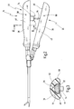
- a medical instrument provided with the general reference numeral 10 is shown.
- the instrument 10 is a needle holder in the embodiment, but in the context of the invention may also be any other medical instrument, for example a forceps for cutting and / or grasping or generally for the preparation of tissue.
- the instrument 10 has a shaft 12, at the distal end of a tool 14 is arranged, which has two jaw parts 16 and 18 in the present embodiment.
- the jaw member 16 is movable while the jaw member 18 is immovable. Between the jaws 16 and 18 can be held when closing the jaw members 16 and 18, a needle, not shown.
- the instrument has a handle 20, which has a first grip part 22 and a second grip part 24.
- the first grip part 22 is immovable while the second grip part 24 is pivotable about a pivot axis 26 relative to the first grip part 22.
- the movable jaw member 16 is closed against the stationary jaw member 18.
- the handle parts 22 and 24 are rod-shaped and take in the present embodiment, a straight course.
- the grip parts 22 and 24 are seen in cross-section (see. Fig. 1 and 3 ) designed to be slim in relation to its length. Accordingly, gripping surfaces 30 and 32 of the handle portions 22 and 24 are narrow and not optimally adapted to the palm of the hand of the operator.
- the gripping surfaces 30 and 32 are formed by the surfaces of the handle parts 22 and 24, namely the mutually remote surfaces of the handle parts 22 and 24.
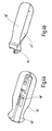
- a handle assembly 34 is provided, which has a first handle shell 36 and a second handle shell 38.
- the handles 36 and 38 are removably attached to the respective handle portion 22 and 24 in the region of the gripping surfaces 30, 32.
- the first grip 36 has a grip surface 40 and the second grip 38 has a second grip surface 42, which, as a comparison of the Fig. 1 and 2 and in particular Fig. 3 shows, compared to the gripping surfaces 30 and 32 of the handle parts 22 and 24 is increased.
- the handles 36 and 38 are formed in size and / or shape so that they are adapted to the needs of the operator.
- the handle shells 36 and 38 are formed in the embodiment shown from the proximal end 52 and 54 forth on the handle parts 22 and 24 pushed.
- the handle shells 36 and 38 each have a longitudinally of the handle shells 36 and 38 extending recess or recess 56 which is formed in the form of a groove, wherein the recess or recess 56 in Fig. 3 for the handle shell 36 is shown in cross section. This is also on Fig. 4b ) or 5a), in which grip shells 36 'and 38' are shown, which have a recess formed as a groove or recess 56 ', which corresponds to the recess 56 of the handle shells 36 and 38.
- the handle parts 22 and 24 in the attached state of the handle shells 36 and 38 at least partially, in the illustrated embodiment of Fig. 1 to 3 seen completely in section.
- the handle shells 36 and 38 each have at least one element 58 and 60 for fixing the handle shells 36 and 38 on the handle parts 22 and 24.
- the elements 58 and 60 are formed, for example, as screws, for example grub screws 62, 64, which are screwed through corresponding openings in the grips 36 and 38, respectively and can be brought into clamping engagement with the handle parts 22 and 24. To the handle parts 22 and 24 but could also threaded or cylindrical holes be present, in which the screws 62, 64 are screwed or can engage.
- the elements 58 and 60 thus set the handles 36 and 38 in the longitudinal direction of the handle parts 22 and 24 fixed to this. Instead of screwing or in addition, however, the handles 36 and 38, for example, by a catch 65 (see. Fig. 5a ) are fixed to the handle parts 22 and 24 respectively.
- a determination of the handle shells 36 and 38 in the embodiment according to Fig. 1 to 3 also realized in that the handle parts 22 and 24 in the respective recess or recess 56 of the handle shell or 38 are substantially bordered on all sides, as from Fig. 3 evident. In this way, the handles 36 and 38 in the transverse direction to the handle parts 22 and 24 can be fixed thereto.
- angular configuration of the handle parts 22 and 24 causes the substantially positive reception of the handle parts 22 and 24 in the grips 36 and 38 and a rotation of the handle shells 36 and 38 about the longitudinal direction of the handle parts 22 and 24th
- the grip 36 '' in the transverse direction, ie transversely to the longitudinal direction of the handle portion 22 '', in particular in the direction of actuation of the handle portion 22 '' set, the handle shell 36 '' at least one tab 66, the handle portion 22 '' at least in part, according to Fig. 6 completely encompassing.
- a plurality of such tabs 66 may be provided, or the recess or recess 56 '' may be designed as in cross-section on all sides closed bore or recess.
- a grip 36 ''' is designed as a clamping part for clamping to the handle part 22.
- the shell 36 '''in the longitudinal direction of the handle portion 22 are slid onto this.
- the grip 36 '''further comprises a recess or recess 56''', in which the handle part 22 is only partially received.
- the handle shell 36''' tabs 68 and 70 which are formed correspondingly elastic and act as terminals.
- the tabs 68 and 70 serve at the same time as elements for fixing the grip 36 '''in the transverse direction to the handle portion 22, ie transversely to the longitudinal direction, in particular in the direction of actuation of the handle portion 22.
- the handle shell 36 '''and transverse to the longitudinal direction of the handle portion 22nd be attached in the manner of a clip on this, wherein when attaching the tabs 68 and 70 then spread apart and then put around the handle portion 22 or close.
- the handle shells 36 and 38 have locking means 72 for locking the handle members 22 and 24 in different relative gripping positions relative to one another.
- the locking means 72 have, for example, a sleeve 74 connected to the handle shell 36 and a handle 38 connected to the pin 76, which engages with frictional engagement in the sleeve 74 and a continuous locking of the handle parts 22 and 24 allows each other.
- handle parts 36 'and 38' can also be attached to the instrument 10 on the handle parts 22 and 24, wherein the handle portion 36 'has a gripping surface 40', which is particularly adapted to the palm in the region of the thumb and preferably has a thumb recess 78 while the grip 38 'has a gripping surface 42' adapted to the lower portion of the palm.
- the gripping surfaces 40 and 42 of the handles 36 and 38 are preferably soft and / or roughened.
- the handles 36 and 38 are also autoclavable.
Landscapes
- Health & Medical Sciences (AREA)
- Surgery (AREA)
- Life Sciences & Earth Sciences (AREA)
- Medical Informatics (AREA)
- Nuclear Medicine, Radiotherapy & Molecular Imaging (AREA)
- Engineering & Computer Science (AREA)
- Biomedical Technology (AREA)
- Heart & Thoracic Surgery (AREA)
- Ophthalmology & Optometry (AREA)
- Molecular Biology (AREA)
- Animal Behavior & Ethology (AREA)
- General Health & Medical Sciences (AREA)
- Public Health (AREA)
- Veterinary Medicine (AREA)
- Infusion, Injection, And Reservoir Apparatuses (AREA)
- Surgical Instruments (AREA)
Description
- Die Erfindung betrifft ein medizinisches Instrument, mit einer Handhabe, die zwei im wesentlichen stabförmige Griffteile aufweist, die jeweils eine Grifffläche aufweisen.
- Aus dem DE-Firmenprospekt der Karl Storz GmbH & Co. KG, STORZ - Karl Storz Endoskope, Band "Endoskopische Chirurgie", 2. Ausgabe 1/94, Seite NH 3 A ist ein medizinisches Instrument in Form eines Nadelhalters bekannt, dessen Handhabe zwei stabförmige Griffteile aufweist, die sehr schlank bauend sind, d.h. einen im Verhältnis zu ihrer Länge kleinen Querschnitt aufweisen. Entsprechend ist die an jedem Griffteil ausgebildete, als Grifffläche dienende Umfangsfläche der Griffteile klein. Die Griffteile dieses bekannten Instruments sind daher möglicherweise als nicht optimal ergonomisch anzusehen, weil die Gesamtgrifffläche der Griffteile dieses Instruments im Verhältnis zur Handinnenfläche der das Instrument bedienenden Person klein ist.
- Die Handhabe eines derartigen Instruments hat nicht nur die Aufgabe, das Instrument in der Hand zu halten, sondern die Griffteile eines solchen Instruments sind üblicherweise relativ zueinander beweglich ausgeführt, um durch Betätigen der Griffteile ein Werkzeug, beispielsweise Maulteile, am distalen Ende des Instruments zu betätigen. Das Betätigen des Werkzeugs am distalen Ende des Instruments mittels der Griffteile am proximalen Ende erfordert in der Regel ein sicheres Handgefühl, das wiederum von den ergonomischen Eigenschaften der Griffteile beeinflußt wird. Somit besteht ein Bedürfnis, die Ergonomie des zuvor genannten Instruments zu verbessern, insbesondere an die jeweiligen Bedürfnisse und Voraussetzungen des bedienenden Arztes anzupassen.
- Daneben sind medizinische Instrumente bekannt, deren Handhabe bzw. Handgriff als Ganzes vom Schaft des Instruments abnehmbar ist, wie beispielsweise in der
DE 198 60 444 A1 beschrieben ist. Es handelt sich dabei um vollwertige Handhaben bzw. Handgriffe, die entsprechend auch mit einer Kraftübertragungsmechanik zum Betätigen des Werkzeugs am distalen Ende des Instruments ausgestattet sind. Mit solchen abnehmbaren Handhaben kann zwar das jeweilige Instrument durch Austauschen des Handgriffs gegen einen anderen an die jeweiligen Bedürfnisse des bedienenden Arztes angepaßt werden, jedoch sind derartige vollwertige bzw. vollständige Handhaben konstruktiv aufwendig und kostspielig, wenn mehrere Sätze derartiger Handhaben unterschiedlicher Größe und Form bereitgehalten werden. - Aus
US-A-3 894 336 ist eine Einwegschere zum Schneiden chirurgischer Bandagen, Nähte und dergleichen bekannt, bei der die als Fingerringe ausgebildeten Griffteile von den Scherenarmen abnehmbar sind. -
DE 42 11 417 A1 offenbart ein chirurgisches Endoinstrument, bei dem die Griffteile vom Instrument abgenommen werden können. -
US-A-1 116 099 offenbart ein chirurgisches Instrument mit abnehmbaren Griffteilen. - Der Erfindung liegt daher die Aufgabe zugrunde, ein medizinisches Instrument bereitzustellen, bei dem mit geringem Kostenaufwand die ergonomischen Eigenschaften des Instruments verbessert, insbesondere an unterschiedliche Bedürfnisse der Bedienungsperson anpassbar sind.
- Erfindungsgemäß wird diese Aufgabe durch ein medizinisches Instrument gemäß Anspruch 1 gelöst.
- Mit der bei dem erfindungsgemäßen Instrument vorgesehenen Griffanordnung kann ein bereits vorhandenes Instrument ohne Veränderung des Instruments selbst hinsichtlich seiner ergonomischen Handhabungseigenschaften verbessert werden, indem an die Griffteile jeweils eine erfindungsgemäß vorgesehene Griffschale angebracht wird, durch die die Grifffläche der Griffteile vergrößert und/oder formverändert wird. Das Halten bzw. Greifen des medizinischen Instruments wird mittels der Griffschalen, die eine neue Grifffläche definieren, wesentlich verbessert. Darüber hinaus können für ein und dasselbe Instrument eine Mehrzahl von Sätzen derartiger Griffschalen mit verschiedenen Größen und/oder Formen bereitgehalten werden, wodurch die Handhabe des Instruments an die jeweiligen Bedürfnisse der Bedienungsperson angepaßt werden kann. Im Unterschied zu einer abnehmbaren vollständigen Handhabe wie im Stand der Technik hat die erfindungsgemäße Griffanordnung den Vorteil, auf wesentlich kostengünstigere Weise eine Veränderung der Handhabungseigenschaften des Instruments zu ermöglichen.
- Die Griffschalen sind vom proximalen Ende der Griffteile auf diese aufschiebbar.
- Zusätzlich können die Griffschalen seitlich auf die Griffteile aufsteckbar sein. Durch diese Maßnahmen können die Griffschalen auf vorteilhaft einfach zu handhabende Weise mit dem jeweiligen Griffteil verbunden werden. Die aufschiebbare Ausgestaltung der Griffschalen eignet sich insbesondere auch für solche Griffteile, die im wesentlichen gerade sind, während die aufsteckbare Variante für geschwungene bzw. gekrümmte Griffteile besser geeignet sein kann. Unter "seitlich" aufsteckbar ist zu verstehen, daß die Griffschalen Seite an Seite mit den Griffteilen liegend quer zur Längsrichtung an die Griffteile anbringbar sind.
- In einer weiteren bevorzugten Ausgestaltung sind die Griffschalen als Klemmteile zum Anklemmen an die Griffteile ausgebildet. Hierbei ist von Vorteil, daß die Griffschalen auf einfach zu handhabende Weise lediglich an die Griffteile angeklemmt werden müssen und dadurch bereits zumindest teilweise oder sogar vollständig fixiert sind, ohne daß weitere Fixierungsmaßnahmen wie Anziehen von Schrauben oder dgl. vorgenommen werden müssen.
- In einer weiteren bevorzugten Ausgestaltung weisen die Griffschalen eine Vertiefung oder Ausnehmung auf, in der die Griffteile in befestigtem Zustand der Griffschalen zumindest teilweise aufgenommen sind.
- Hierbei ist von Vorteil, daß sich die Griffschalen an den Griffteilen mit besonders sicherem Halt verbinden lassen, wobei, wie in einer weiteren bevorzugten Ausgestaltung vorgesehen ist, die Vertiefungen bzw. Ausnehmungen auch so ausgebildet werden können, daß die Griffteile im wesentlichen formschlüssig darin aufgenommen werden. Auf diese Weise ist es möglich, die Griffschalen bei entsprechender Formgebung der Vertiefungen oder Ausnehmungen auch verdrehgesichert an den Griffteilen in einer vorbestimmten, durch den Formschluß leicht auffindbaren Drehposition zu verbinden.
- In diesem Zusammenhang ist es weiterhin bevorzugt, wenn die Vertiefungen oder Ausnehmungen so ausgebildet sind, daß die Griffteile darin im Querschnitt gesehen vollständig aufgenommen sind.
- Hierbei ist von Vorteil, daß die im befestigten Zustand der Griffschalen an den Griffteilen einander zugewandten Seiten der Griffschalen eine gleichmäßige kantenfreie Oberfläche bilden können. Die Vertiefungen oder Ausnehmungen können dann als allseitig geschlossene Bohrungen bzw. Öffnungen ausgebildet sein.
- In einer weiteren bevorzugten Ausgestaltung sind im an den Griffteilen befestigten Zustand einander zugewandte Seiten der Griffschalen randseitig jeweils abgerundet ausgebildet.
- Diese Maßnahme hat insbesondere dann einen Vorteil, wenn beide Griffteile bis zur Anlage aneinander geschlossen werden können. Durch die randseitige Abrundung der einander zugewandten Seiten der Griffschalen wird nun vorteilhafterweise vermieden, daß beim Zudrücken der Griffteile Haut, vor allem Haut der Handunterkante, zwischen den Griffschalen eingeklemmt wird. Eine andere Möglichkeit, ein derartiges Einklemmen von Haut zu vermeiden, besteht darin, die Griffschalen so auszugestalten, sei es mit einer Vertiefung/Ausnehmung oder ohne, daß die einander zugewandten Seiten der Griffschalen von den einander zugewandten Seiten der Griffteile zurück versetzt sind.
- In einer weiteren bevorzugten Ausgestaltung weisen die Griffschalen jeweils zumindest ein Element zum Festlegen der Griffschalen an den Griffteilen in Längsrichtung und/oder Querrichtung zu den Griffteilen und/oder zum Verdrehsichern der Griffschalen um die Längsrichtung der Griffteile auf.
- Mittels dieser Maßnahmen kann sicher gewährleistet werden, daß sich die Griffschalen bei der Bedienung des Instruments relativ zu den Griffteilen, an denen sie befestigt sind, nicht verschieben bzw. verdrehen oder von den Griffteilen unerwünscht abheben lassen.
- Dabei ist es bevorzugt, wenn das zumindest eine Element eine Schraube oder eine Raste ist.
- Mit einer Schraube, beispielsweise in Form einer Madenschraube, die von außen durch die Griffschale eingedreht wird und beispielsweise gegen das entsprechende Griffteil klemmend in Anlage kommt, kann ein besonders sicherer Halt der Griffschalen insbesondere gegen Verschiebung in Längsrichtung bzw. gegen ein Verdrehen um die Längsrichtung an den Griffteilen erreicht werden, während der Vorteil einer Raste als Sicherungselement darin besteht, daß das Anbringen der Griffschalen an den Griffteilen erleichtert ist, weil keine Schraube angezogen werden muß. Mit einer Schraube kann die jeweilige Griffschale auf dem Griffteil auch formschlüssig, beispielsweise durch Einschrauben der Schraube in ein Gewinde- oder Zylinderloch am Griffteil, befestigt werden.
- Als weitere bevorzugte Ausgestaltung des zumindest einen Elements zum Festlegen der Griffschalen an den Griffteilen ist das zumindest eine Element eine Lasche, die das entsprechende Griffteil zumindest teilweise umgreift.
- Eine solche Lasche sichert die Griffschalen an den Griffteilen vorteilhafterweise besonders wirksam in Querrichtung zu den Griffteilen.
- Das zumindest eine Element, um eine Verdrehsicherung der Griffschalen um die Griffteile zu vermeiden, kann vorteilhafterweise auch durch die bereits zuvor genannten Ausnehmungen oder Vertiefungen in den Griffschalen selbst gebildet werden, wenn die Ausnehmungen oder Vertiefungen so ausgebildet sind, daß sie eine im wesentlichen formschlüssige Aufnahme der Griffteile ermöglichen und die Griffteile im Querschnitt nicht rund sind.
- In einer weiteren bevorzugten Ausgestaltung weisen die Griffschalen jeweils eine weiche und/oder aufgerauhte Grifffläche auf.
- Mit einer weichen Oberfläche werden die ergonomischen Eigenschaften der Griffanordnung vorteilhafterweise weiter verbessert, und mit einer aufgerauhten Oberfläche kann vorteilhafterweise vermieden werden, daß die Griffschalen in der Hand der Bedienungsperson rutschen.
- In einer weiteren bevorzugten Ausgestaltung weisen die Griffschalen Verriegelungsmittel zum Verriegeln der Griffteile in verschiedenen relativen Griffstellungen zueinander auf, die vorzugsweise eine stufenlose Verriegelung ermöglichen.
- In dieser Ausgestaltung wird mit den erfindungsgemäßen Griffschalen nicht nur eine verbesserte Ergonomie eines medizinischen Instruments erreicht, sondern es kann den Griffteilen eine weitere Funktion gegeben werden, die sie ohne die erfindungsgemäßen Griffschalen vorher ggf. nicht hatten. Diese Funktion besteht darin, die beiden Griffteile in unterschiedlichen Griffstellungen relativ zueinander zu verriegeln. Während bei den bekannten Nadelhaltern die Griffteile bereits mittels eines Rastgesperres in verschiedenen Griffstellungen verriegelbar sind, kann mittels der erfindungsgemäßen Griffschalen nun auch eine stufenlose Verriegelung ermöglicht werden, beispielsweise durch zwei an den Griffschalen vorhandene Elemente, die reibschlüssig zusammenwirken.
- Wie bereits weiter oben erwähnt, weist die erfindungsgemäße Griffanordnung vorzugsweise eine Mehrzahl von Sätzen von Griffschalen unterschiedlicher Größen und/oder Formen auf, wodurch ein bereits vorhandenes Instrument an verschiedene Bedürfnisse verschiedener Bedienungspersonen oder auch an verschiedene Bedürfnisse derselben Bedienungsperson für verschiedene Anwendungen angepaßt werden kann.
- Die erfindungsgemäß vorgesehenen Griffschalen sind vorzugsweise reinigbar, insbesondere autoklavierbar. Hieraus ergibt sich ein weiterer Vorteil der erfindungsgemäßen Griffanordnung gegenüber solchen Instrumenten, deren Handhabe als Ganzes vom Schaft des Instruments abnehmbar ist. Denn vollwertige abnehmbare Handhaben besitzen aufgrund ihres aufwendigeren Aufbaus zahlreiche Ecken und Nischen, in denen sich Verunreinigungen ansammeln können, die sich nur schwer reinigen lassen. Demgegenüber können die konstruktiv sehr einfach gestalteten Griffschalen einteilig und mit nur wenigen Ecken und Nischen ausgebildet werden, so daß sich Verunreinigungen weniger stark ansammeln oder zumindest leichter entfernen lassen.
- Weitere Vorteile und Merkmale ergeben sich aus der nachfolgenden Beschreibung und der beigefügten Zeichnung.
- Es versteht sich, daß die vorstehend genannten und nachstehend noch zu erläuternden Merkmale nicht nur in der jeweils angegebenen Kombination, sondern auch in anderen Kombinationen verwendbar sind.
- Ausführungsbeispiele der Erfindung sind in den Zeichnungen dargestellt und werden mit Bezug auf diese hiernach näher beschrieben. Es zeigen:
- Fig. 1
- eine Seitenansicht eines medizinischen Instruments;
- Fig. 2
- das Instrument in
Fig. 1 mit einer daran abnehmbar befestigten erfindungsgemäßen Griffanordnung; - Fig. 3
- einen Schnitt entlang der Linie III-III in
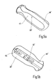
Fig. 2 in geringfügig vergrößertem Maßstab; - Fig. 4a) und 4b)
- ein weiteres Ausführungsbeispiel einer Griffschale einer erfindungsgemäßen Griffanordnung, wobei
Fig. 4a ) die Griffschale in einer perspektivischen Draufsicht undFig. 4b ) die Griffschale inFig. 4a ) in einer perspektivischen Ansicht von unten zeigt; - Fig. 5a) und b)
-
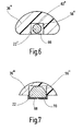
Fig. 4a ) und b) entsprechende Darstellungen eines weiteres Ausführungsbeispiels einer Griffschale; - Fig. 6 und 7
- zwei
Fig. 3 entsprechende Schnittdarstellungen von weiteren Ausführungsbeispielen von Griffanordnungen. - In
Fig. 1 bis 3 ist ein mit dem allgemeinen Bezugszeichen 10 versehenes medizinisches Instrument dargestellt. Das Instrument 10 ist in dem Ausführungsbeispiel ein Nadelhalter, kann jedoch im Rahmen der Erfindung auch ein beliebiges anderes medizinisches Instrument, beispielsweise eine Zange zum Schneiden und/oder Fassen oder allgemein zum Präparieren von Gewebe sein. - Das Instrument 10 weist einen Schaft 12 auf, an dessen distalem Ende ein Werkzeug 14 angeordnet ist, das im vorliegenden Ausführungsbeispiel zwei Maulteile 16 und 18 aufweist. Das Maulteil 16 ist beweglich, während das Maulteil 18 unbeweglich ist. Zwischen den Maulteilen 16 und 18 kann beim Schließen der Maulteile 16 und 18 eine nicht dargestellte Nadel gehalten werden.
- Am proximalen Ende des Schafts 12 weist das Instrument eine Handhabe 20 auf, die ein erstes Griffteil 22 und ein zweites Griffteil 24 aufweist. Das erste Griffteil 22 ist unbeweglich, während das zweite Griffteil 24 relativ zu dem ersten Griffteil 22 um eine Schwenkachse 26 verschwenkbar ist. Durch Verschwenken des zweiten Griffteils 24 in Richtung eines Pfeiles 28 wird das bewegliche Maulteil 16 gegen das unbewegliche Maulteil 18 geschlossen. Die Kraftübertragung von dem beweglichen Griffteil 24 auf das bewegliche Maulteil 16 erfolgt über eine nicht näher dargestellte Kraftübertragungsmechanik, die eine Zugstange aufweist, wie sie bei derartigen Instrumenten üblich ist.
- Die Griffteile 22 und 24 sind stabförmig ausgebildet und nehmen im vorliegenden Ausführungsbeispiel einen geraden Verlauf ein. Die Griffteile 22 und 24 sind im Querschnitt gesehen (vgl.
Fig. 1 und3 ) im Verhältnis zu ihrer Länge schlank bauend ausgebildet. Entsprechend sind Griffflächen 30 und 32 der Griffteile 22 und 24 schmal und nicht optimal an die Handinnenfläche der Hand der Bedienungsperson angepaßt. Die Griffflächen 30 und 32 werden durch die Oberflächen der Griffteile 22 und 24, und zwar der voneinander abgewandten Oberflächen der Griffteile 22 und 24 gebildet. - Um die Griffflächen 30 und 32 der Griffteile 22 und 24 zu vergrößern und ggf. in der Form zu verändern und damit insgesamt ergonomischer zu gestalten, ist gemäß
Fig. 2 eine Griffanordnung 34 vorgesehen, die eine erste Griffschale 36 und eine zweite Griffschale 38 aufweist. - Die Griffschalen 36 und 38 sind an dem jeweiligen Griffteil 22 und 24 im Bereich deren Griffflächen 30, 32 abnehmbar befestigt.
- Die erste Griffschale 36 weist eine Grifffläche 40 und die zweite Griffschale 38 weist eine zweite Grifffläche 42 auf, die, wie aus einem Vergleich der
Fig. 1 und2 und insbesondere ausFig. 3 hervorgeht, gegenüber den Griffflächen 30 und 32 der Griffteile 22 und 24 vergrößert ist. - Die Griffschalen 36 und 38 sind hinsichtlich Größe und/oder Form so ausgebildet, daß sie an die jeweiligen Bedürfnisse der Bedienungsperson angepaßt sind.
- Im befestigten Zustand der Griffschalen 36 und 38 einander zugewandte Seiten 44 und 46 der Griffschalen 36 und 38 sind randseitig jeweils abgerundet ausgebildet, wie in
Fig. 3 für die Griffschale 36 dargestellt ist, die Abrundungen 48 und 50 aufweist. Durch die Abrundungen 48 und 50 wird vermieden, daß Haut der das Instrument 10 haltenden Hand der Bedienungsperson zwischen den Griffschalen 36 und 38 beim Schließen bzw. Zusammendrücken der Griffteile 22 und 24 eingeklemmt wird. - Die Griffschalen 36 und 38 sind in dem gezeigten Ausführungsbeispiel vom proximalen Ende 52 bzw. 54 her auf die Griffteile 22 bzw. 24 aufschiebbar ausgebildet.
- Die Griffschalen 36 und 38 weisen jeweils eine sich in Längsrichtung der Griffschalen 36 und 38 erstreckende Vertiefung oder Ausnehmung 56 auf, die in Form einer Nut ausgebildet ist, wobei die Ausnehmung oder Vertiefung 56 in
Fig. 3 für die Griffschale 36 im Querschnitt dargestellt ist. Hierzu wird auch aufFig. 4b ) bzw. 5a) verwiesen, in denen Griffschalen 36' bzw. 38' dargestellt sind, die eine als Nut ausgebildete Vertiefung oder Ausnehmung 56' aufweisen, die der Vertiefung 56 der Griffschalen 36 und 38 entspricht. - In der Vertiefung oder Ausnehmung 56 sind die Griffteile 22 bzw. 24 im befestigten Zustand der Griffschalen 36 und 38 zumindest teilweise, im gezeigten Ausführungsbeispiel der
Fig. 1 bis 3 im Querschnitt gesehen vollständig aufgenommen. - Die Griffschalen 36 und 38 weisen jeweils zumindest ein Element 58 und 60 zum Festlegen der Griffschalen 36 und 38 an den Griffteilen 22 und 24 auf.
- Die Elemente 58 und 60 sind beispielsweise als Schrauben, beispielsweise Madenschrauben 62, 64 ausgebildet, die durch entsprechende Öffnungen in den Griffschalen 36 bzw. 38 eingedreht und mit den Griffteilen 22 und 24 klemmend in Eingriff gebracht werden können. Zu den Griffteilen 22 und 24 könnten aber auch Gewinde- oder Zylinderlöcher vorhanden sein, in die die Schrauben 62, 64 eingedreht werden oder eingreifen können. Die Elemente 58 bzw. 60 legen damit die Griffschalen 36 bzw. 38 in Längsrichtung der Griffteile 22 bzw. 24 an diesen fest. Anstelle durch Verschraubung oder zusätzlich können die Griffschalen 36 und 38 jedoch auch beispielsweise durch eine Raste 65 (vgl.
Fig. 5a ) an den Griffteilen 22 bzw. 24 festgelegt werden. - Darüber hinaus wird eine Festlegung der Griffschalen 36 und 38 bei dem Ausführungsbeispiel gemäß
Fig. 1 bis 3 auch dadurch realisiert, daß die Griffteile 22 und 24 in der jeweiligen Vertiefung oder Ausnehmung 56 der Griffschale bzw. 38 allseitig im wesentlichen eingefaßt sind, wie ausFig. 3 hervorgeht. Auf diese Weise sind die Griffschalen 36 und 38 auch in Querrichtung zu den Griffteilen 22 und 24 an diesen festlegbar. - Gemäß der in dem Ausführungsbeispiel der
Fig. 1 bis 3 im Querschnitt nicht runden, sondern eckigen Ausgestaltung der Griffteile 22 und 24 bewirkt die im wesentlichen formschlüssige Aufnahme der Griffteile 22 und 24 in den Griffschalen 36 bzw. 38 auch eine Verdrehsicherung der Griffschalen 36 und 38 um die Längsrichtung der Griffteile 22 bzw. 24. - Im Falle einer zylindrischen Ausgestaltung eines Griffteils 22" können jedoch auch Schrauben eine derartige Verdrehsicherung bewirken, wie beispielsweise in
Fig. 6 für ein Griffteil 22" mit rundem Querschnitt und einer Griffschale 36'' mit Schraube 62'' dargestellt ist, bei der das Griffteil 24' in der Ausnehmung oder Vertiefung 56'' der Griffschale 36'' nicht formschlüssig aufgenommen ist. - Um bei dem in
Fig. 6 dargestellten Ausführungsbeispiel die Griffschale 36'' auch in Querrichtung, d.h. quer zur Längsrichtung des Griffteils 22'', insbesondere in Betätigungsrichtung des Griffteils 22'', festzulegen, weist die Griffschale 36'' zumindest eine Lasche 66 auf, die das Griffteil 22'' zumindest teilweise, gemäßFig. 6 vollständig umgreift. Über die Länge der Griffschale 36'' können eine Mehrzahl derartiger Laschen 66 vorgesehen sein, oder die Vertiefung bzw. Ausnehmung 56'' kann als im Querschnitt allseitig geschlossene Bohrung oder Ausnehmung ausgeführt sein. - In
Fig. 7 ist ein Ausführungsbeispiel dargestellt, wonach eine Griffschale 36''' als Klemmteil zum Anklemmen an das Griffteil 22 ausgebildet ist. In dieser Ausgestaltung kann die Schale 36''' in Längsrichtung des Griffteils 22 auf dieses aufgeschoben werden. Bei dem inFig. 7 dargestellten Ausführungsbeispiel weist die Griffschale 36''' ferner eine Vertiefung oder Ausnehmung 56''' auf, in der das Griffteil 22 nur teilweise aufgenommen ist. Zum Anklemmen der Griffschale 36''' an dem Griffteil 22 weist die Griffschale 36''' Laschen 68 und 70 auf, die entsprechend elastisch ausgebildet sind und als Klemmen wirken. Die Laschen 68 und 70 dienen gleichzeitig als Elemente zum Festlegen der Griffschale 36''' in Querrichtung zu dem Griffteil 22, d.h. quer zur Längsrichtung, insbesondere in Betätigungsrichtung des Griffteils 22. Bei entsprechender Ausgestaltung der Laschen 68 und 70 als elastische Elemente und bei entsprechender Geometrie der Laschen 68 und 70 könnte die Griffschale 36''' auch quer zur Längsrichtung des Griffteils 22 in der Art eines Clips auf dieses aufgesteckt werden, wobei beim Aufstecken die Laschen 68 und 70 sich dann auseinanderspreizen und anschließend um das Griffteil 22 herumlegen bzw. schließen. - Wieder mit Bezug auf
Fig. 2 und 3 weisen die Griffschalen 36 und 38 Verriegelungsmittel 72 zum Verriegeln der Griffteile 22 und 24 in verschiedenen relativen Griffstellungen zueinander auf. Die Verriegelungsmittel 72 weisen beispielsweise eine mit der Griffschale 36 verbundene Hülse 74 und einen mit der Griffschale 38 verbundenen Stift 76 auf, der unter Reibschluß in die Hülse 74 eingreift und eine stufenlose Verriegelung der Griffteile 22 und 24 aneinander ermöglicht. - Die in
Fig. 4 und5 dargestellten Griffteile 36' und 38' können ebenfalls bei dem Instrument 10 an den Griffteilen 22 und 24 befestigt werden, wobei das Griffteil 36' eine Grifffläche 40' aufweist, die insbesondere an die Handinnenfläche im Bereich des Daumens angepaßt ist und vorzugsweise eine Daumenmulde 78 aufweist, während die Griffschale 38' eine Grifffläche 42' aufweist, die an den unteren Bereich der Handinnenfläche angepaßt ist. - Die Griffflächen 40 und 42 der Griffschalen 36 und 38 sind vorzugsweise weich und/oder aufgerauht. Die Griffschalen 36 und 38 sind ferner autoklavierbar.
- Es versteht sich, daß für das Instrument 10 mehrere Sätze von Griffschalen 36 und 38 unterschiedlicher Größe und/oder unterschiedlicher Formen bereitgehalten werden können, um die Handhabe 20 des Instruments 10 an die jeweiligen Bedürfnisse und Anforderungen der Bedienungsperson anpaßbar zu machen.
Claims (14)
- Medizinisches Instrument (10), mit einer Handhabe (20), die zwei im wesentlichen stabförmige Griffteile (22, 24; 22'') aufweist, die jeweils eine Grifffläche (30, 32) aufweisen, und mit einer Griffanordnung (34), die für jedes Griffteil (22, 24; 22'') eine an dem jeweiligen Griffteil (22, 24; 22'') im Bereich deren Grifffläche (30, 32) abnehmbar befestigbare Griffschale (36, 38; 36', 38'; 36''; 36''') mit jeweils einer gegenüber der Grifffläche (30, 32) der Griffteile (22, 24; 22'') vergrößerten und/oder formveränderten Grifffläche (40, 42; 40', 42') aufweist dadurch charakterisiert, dass die Griffschalen (36, 38; 36', 38'; 36''; 36''') zum greifen des medirinischen Instruments vom proximalen Ende der Griffteile (22, 24; 22'') her auf die-se aufschiebbar ausgebildet sind.
- Instrument nach Anspruch 1, wobei die Griffschalen (36, 38; 36', 38'; 36'';36''') seitlich auf die Griffteile (22, 24; 22'') aufsteckbar ausgebildet sind.
- Instrument nach Anspruch 1 oder 2, wobei die Griffschalen (36''') als Klemmteile zum Anklemmen an die Griffteile (22, 24) ausgebildet sind.
- Instrument nach einem der Ansprüche 1 bis 3, wobei die Griffschalen (36, 38; 36', 38'; 36''; 36''') eine Vertiefung oder Ausnehmung (56; 56'; 56''; 56''') aufweisen, in der die Griffteile (22, 24; 22'') im befestigten Zustand der Griffschalen (36, 38; 36', 38'; 36''; 36''') zumindest teilweise aufgenommen sind.
- Instrument nach Anspruch 4, wobei die Vertiefungen oder Ausnehmungen (56; 56'; 56'') so ausgebildet sind, daß die Griffteile (22, 24; 22'') darin im Querschnitt gesehen vollständig aufgenommen sind.
- Instrument nach einem der Ansprüche 1 bis 5, wobei im an den Griffteilen (22, 24; 22'') befestigten Zustand einander zugewandte Seiten (44, 46) der Griffschalen (36, 38; 36', 38'; 36'') randseitig jeweils abgerundet ausgebildet sind.
- Instrument nach einem der Ansprüche 1 bis 6, wobei die Griffschalen (36, 38; 36', 38'; 36''; 36''') jeweils zumindest ein Element (58, 60) zum Festlegen der Griffschalen an den Griffteilen (22, 24; 22'') in Längsrichtung und/oder Querrichtung zu den Griffteilen (22, 24; 22'') und/oder zum Verdrehsichern der Griffschalen (36, 38; 36', 38'; 36"; 36''') um die Längsrichtung der Griffteile (22, 24; 22'') aufweisen.
- Instrument nach Anspruch 7, wobei das zumindest eine Element (58, 60) eine Schraube (62, 62) oder eine Raste (65) ist.
- Instrument nach Anspruch 7 oder 8, wobei das zumindest eine Element eine Lasche (66; 68, 70) ist, die das entsprechende Griffteil (22; 22'') zumindest teilweise umgreift.
- Instrument nach Anspruch 4 oder einem der Ansprüche 5 bis 9, soweit diese auf Anspruch 4 rückbezogen sind, wobei die Ausnehmungen oder Vertiefungen (56; 56'; 56''') zur im wesentlichen formschlüssigen Aufnahme der Griffteile (22, 24) ausgebildet sind.
- Instrument nach einem der Ansprüche 1 bis 10, wobei die Griffschalen (36, 38; 36', 38'; 36"; 36''') jeweils eine weiche und/oder aufgerauhte Grifffläche aufweisen.
- Instrument nach einem der Ansprüche 1 bis 11, wobei die Griffschalen (36, 38) Verriegelungsmittel (72) zum Verriegeln der Griffteile (22, 24) in verschiedenen relativen Griffstellungen aufweisen, die vorzugsweise eine stufenlose Verriegelung ermöglichen.
- Instrument nach einem der Ansprüche 1 bis 12, wobei es eine Mehrzahl von Sätzen von Griffschalen (36, 38; 36', 38'; 36''; 36''') unterschiedlicher Größen und/oder Formen aufweist.
- Instrument nach einem der Ansprüche 1 bis 13, wobei die Griffschalen (36, 38; 36', 38'; 36'';36''') autoklavierbar sind.
Applications Claiming Priority (3)
| Application Number | Priority Date | Filing Date | Title |
|---|---|---|---|
| DE2002122042 DE10222042B3 (de) | 2002-05-10 | 2002-05-10 | Griffanordnung für ein medizinisches Instrument sowie derartiges medizinisches Instrument |
| DE10222042 | 2002-05-10 | ||
| PCT/EP2003/004289 WO2003094755A1 (de) | 2002-05-10 | 2003-04-25 | Griffanordnung für ein medizinisches instrument sowie derartiges medizinisches instrument |
Publications (2)
| Publication Number | Publication Date |
|---|---|
| EP1519689A1 EP1519689A1 (de) | 2005-04-06 |
| EP1519689B1 true EP1519689B1 (de) | 2013-09-04 |
Family
ID=29413920
Family Applications (1)
| Application Number | Title | Priority Date | Filing Date |
|---|---|---|---|
| EP03725091.7A Expired - Lifetime EP1519689B1 (de) | 2002-05-10 | 2003-04-25 | Medizinisches Instrument mit Griffanordnung |
Country Status (3)
| Country | Link |
|---|---|
| EP (1) | EP1519689B1 (de) |
| DE (1) | DE10222042B3 (de) |
| WO (1) | WO2003094755A1 (de) |
Families Citing this family (3)
| Publication number | Priority date | Publication date | Assignee | Title |
|---|---|---|---|---|
| US8167904B2 (en) | 2002-05-10 | 2012-05-01 | Karl Storz Gmbh & Co. Kg | Grip arrangement for a medical instrument, and such medical instrument |
| DE102009025663A1 (de) | 2009-06-17 | 2010-12-30 | Karl Storz Gmbh & Co. Kg | Medizinisches Instrument |
| DE202023101127U1 (de) * | 2023-03-09 | 2024-06-24 | Aesculap Ag | Manuell ergreifbares und umgreifbares Griffteil für ein chirurgisches Instrument und ein chirurgisches Instrument |
Family Cites Families (7)
| Publication number | Priority date | Publication date | Assignee | Title |
|---|---|---|---|---|
| US1116099A (en) * | 1912-02-15 | 1914-11-03 | Nathan C Morse | Surgical instrument. |
| US3894336A (en) * | 1973-11-14 | 1975-07-15 | Johnson & Johnson | Suture removal scissor |
| US4961742A (en) * | 1989-03-24 | 1990-10-09 | Torre Randall J | Suture needle holding instrument |
| DE4211417A1 (de) * | 1992-04-04 | 1993-10-07 | Rema Medizintechnik Gmbh | Chirurgisches Endoinstrument |
| US5690636A (en) * | 1995-12-21 | 1997-11-25 | Johnson & Johnson Professional, Inc. | Punch system for tibial prosthesis |
| DE19860444C2 (de) * | 1998-12-28 | 2001-03-29 | Storz Karl Gmbh & Co Kg | Handgriff für ein medizinisches Rohrschaftinstrument |
| US6108845A (en) * | 1999-02-08 | 2000-08-29 | Hung; Shen Chi | Tool combination having detachable handle |
-
2002
- 2002-05-10 DE DE2002122042 patent/DE10222042B3/de not_active Expired - Lifetime
-
2003
- 2003-04-25 EP EP03725091.7A patent/EP1519689B1/de not_active Expired - Lifetime
- 2003-04-25 WO PCT/EP2003/004289 patent/WO2003094755A1/de not_active Ceased
Also Published As
| Publication number | Publication date |
|---|---|
| EP1519689A1 (de) | 2005-04-06 |
| WO2003094755A8 (de) | 2004-01-22 |
| DE10222042B3 (de) | 2004-01-08 |
| WO2003094755A1 (de) | 2003-11-20 |
Similar Documents
| Publication | Publication Date | Title |
|---|---|---|
| EP0688187B1 (de) | Medizinische zange | |
| DE60013280T2 (de) | Chirurgische klammer mit austauschbarer klemme | |
| DE4216971C2 (de) | Zange zum Fassen und Halten von Gewebe oder dergleichen | |
| EP2792325B1 (de) | Chirurgisches Instrument | |
| EP0860148A2 (de) | Bajonettkupplung zum lösbaren Verbinden zweier Rohrschaftinstrumente oder -instrumententeile | |
| EP2510887B1 (de) | Werkzeug für ein mikroinvasives-chirurgisches Instrument | |
| EP0222971A1 (de) | Schraubendreher, insbesondere für chirurgische Zwecke | |
| EP2112909A1 (de) | Chirurgisches instrument | |
| DE9210327U1 (de) | Zangengriff für medizinische Gerätschaften | |
| WO2000016709A1 (de) | Repositionsinstrument zur fixation von knochenfrakturen | |
| DE102006052407A1 (de) | Chirurgisches Maulinstrument mit Elektrode und Kabel | |
| EP3756833A1 (de) | Seitenhandgriff für eine elektrische handwerkzeugmaschine | |
| DE102016117052A1 (de) | Chirurgisches Handinstrument und Handgriff mit Sperreinrichtung | |
| EP3773241B1 (de) | Medizinisches instrument | |
| DE10341561B4 (de) | Medizinisches Gerät | |
| EP1519689B1 (de) | Medizinisches Instrument mit Griffanordnung | |
| DE19700474A1 (de) | Chirurgisches Instrument | |
| DE19909224B4 (de) | Montagezange mit verstellbarer Maulweite | |
| DE2926556A1 (de) | Werkzeughalter, vorzugsweise fuer zahntechnische zwecke | |
| WO2016177467A1 (de) | Chirurgisches handinstrument | |
| EP2263574B1 (de) | Medizinisches Instrument | |
| DE102013105240A1 (de) | Stabhaltezange mit Winkelverstellung | |
| DE19719090A1 (de) | Chirurgisches Instrument | |
| EP1491155A1 (de) | Schiebeschaftinstrument für chirurgische Zwecke, insbesondere Knochen- und Gewebestanze | |
| EP2755581B1 (de) | Chirurgisches rohrschaftinstrument |
Legal Events
| Date | Code | Title | Description |
|---|---|---|---|
| PUAI | Public reference made under article 153(3) epc to a published international application that has entered the european phase |
Free format text: ORIGINAL CODE: 0009012 |
|
| 17P | Request for examination filed |
Effective date: 20041208 |
|
| AK | Designated contracting states |
Kind code of ref document: A1 Designated state(s): AT BE BG CH CY CZ DE DK EE ES FI FR GB GR HU IE IT LI LU MC NL PT RO SE SI SK TR |
|
| RBV | Designated contracting states (corrected) |
Designated state(s): DE FR GB IT |
|
| 17Q | First examination report despatched |
Effective date: 20091221 |
|
| RIC1 | Information provided on ipc code assigned before grant |
Ipc: A61B 17/28 20060101AFI20130218BHEP Ipc: A61B 17/29 20060101ALI20130218BHEP |
|
| GRAP | Despatch of communication of intention to grant a patent |
Free format text: ORIGINAL CODE: EPIDOSNIGR1 |
|
| INTG | Intention to grant announced |
Effective date: 20130419 |
|
| GRAS | Grant fee paid |
Free format text: ORIGINAL CODE: EPIDOSNIGR3 |
|
| GRAA | (expected) grant |
Free format text: ORIGINAL CODE: 0009210 |
|
| AK | Designated contracting states |
Kind code of ref document: B1 Designated state(s): FR GB IT |
|
| RBV | Designated contracting states (corrected) |
Designated state(s): FR GB IT |
|
| REG | Reference to a national code |
Ref country code: DE Ref legal event code: R108 Ref country code: GB Ref legal event code: FG4D |
|
| REG | Reference to a national code |
Ref country code: DE Ref legal event code: R108 Effective date: 20130904 |
|
| PLBE | No opposition filed within time limit |
Free format text: ORIGINAL CODE: 0009261 |
|
| STAA | Information on the status of an ep patent application or granted ep patent |
Free format text: STATUS: NO OPPOSITION FILED WITHIN TIME LIMIT |
|
| 26N | No opposition filed |
Effective date: 20140605 |
|
| REG | Reference to a national code |
Ref country code: FR Ref legal event code: PLFP Year of fee payment: 14 |
|
| PGFP | Annual fee paid to national office [announced via postgrant information from national office to epo] |
Ref country code: IT Payment date: 20160324 Year of fee payment: 14 |
|
| REG | Reference to a national code |
Ref country code: FR Ref legal event code: PLFP Year of fee payment: 15 |
|
| REG | Reference to a national code |
Ref country code: FR Ref legal event code: PLFP Year of fee payment: 16 |
|
| PG25 | Lapsed in a contracting state [announced via postgrant information from national office to epo] |
Ref country code: IT Free format text: LAPSE BECAUSE OF NON-PAYMENT OF DUE FEES Effective date: 20170425 |
|
| PGFP | Annual fee paid to national office [announced via postgrant information from national office to epo] |
Ref country code: GB Payment date: 20220323 Year of fee payment: 20 |
|
| PGFP | Annual fee paid to national office [announced via postgrant information from national office to epo] |
Ref country code: FR Payment date: 20220323 Year of fee payment: 20 |
|
| REG | Reference to a national code |
Ref country code: GB Ref legal event code: PE20 Expiry date: 20230424 |
|
| P01 | Opt-out of the competence of the unified patent court (upc) registered |
Effective date: 20230527 |
|
| PG25 | Lapsed in a contracting state [announced via postgrant information from national office to epo] |
Ref country code: GB Free format text: LAPSE BECAUSE OF EXPIRATION OF PROTECTION Effective date: 20230424 |