EP1519405A2 - Elektrodenloses Beleuchtungssystem - Google Patents
Elektrodenloses Beleuchtungssystem Download PDFInfo
- Publication number
- EP1519405A2 EP1519405A2 EP03293315A EP03293315A EP1519405A2 EP 1519405 A2 EP1519405 A2 EP 1519405A2 EP 03293315 A EP03293315 A EP 03293315A EP 03293315 A EP03293315 A EP 03293315A EP 1519405 A2 EP1519405 A2 EP 1519405A2
- Authority
- EP
- European Patent Office
- Prior art keywords
- lighting system
- electrodeless
- bulb
- stud
- resonator
- Prior art date
- Legal status (The legal status is an assumption and is not a legal conclusion. Google has not performed a legal analysis and makes no representation as to the accuracy of the status listed.)
- Withdrawn
Links
- 239000000463 material Substances 0.000 claims abstract description 19
- 230000005672 electromagnetic field Effects 0.000 claims abstract description 17
- 239000004020 conductor Substances 0.000 claims 2
- 238000001816 cooling Methods 0.000 description 4
- XKRFYHLGVUSROY-UHFFFAOYSA-N Argon Chemical compound [Ar] XKRFYHLGVUSROY-UHFFFAOYSA-N 0.000 description 2
- BUGBHKTXTAQXES-UHFFFAOYSA-N Selenium Chemical compound [Se] BUGBHKTXTAQXES-UHFFFAOYSA-N 0.000 description 1
- NINIDFKCEFEMDL-UHFFFAOYSA-N Sulfur Chemical compound [S] NINIDFKCEFEMDL-UHFFFAOYSA-N 0.000 description 1
- 230000003213 activating effect Effects 0.000 description 1
- 229910052786 argon Inorganic materials 0.000 description 1
- 239000007789 gas Substances 0.000 description 1
- -1 halide compound Chemical class 0.000 description 1
- 229910052743 krypton Inorganic materials 0.000 description 1
- DNNSSWSSYDEUBZ-UHFFFAOYSA-N krypton atom Chemical compound [Kr] DNNSSWSSYDEUBZ-UHFFFAOYSA-N 0.000 description 1
- 239000002184 metal Substances 0.000 description 1
- 230000004048 modification Effects 0.000 description 1
- 238000012986 modification Methods 0.000 description 1
- 229910052711 selenium Inorganic materials 0.000 description 1
- 239000011669 selenium Substances 0.000 description 1
- 238000001228 spectrum Methods 0.000 description 1
- 229910052717 sulfur Inorganic materials 0.000 description 1
- 239000011593 sulfur Substances 0.000 description 1
- 229910052724 xenon Inorganic materials 0.000 description 1
- FHNFHKCVQCLJFQ-UHFFFAOYSA-N xenon atom Chemical compound [Xe] FHNFHKCVQCLJFQ-UHFFFAOYSA-N 0.000 description 1
Images


Classifications
-
- H—ELECTRICITY
- H01—ELECTRIC ELEMENTS
- H01J—ELECTRIC DISCHARGE TUBES OR DISCHARGE LAMPS
- H01J65/00—Lamps without any electrode inside the vessel; Lamps with at least one main electrode outside the vessel
-
- H—ELECTRICITY
- H01—ELECTRIC ELEMENTS
- H01J—ELECTRIC DISCHARGE TUBES OR DISCHARGE LAMPS
- H01J65/00—Lamps without any electrode inside the vessel; Lamps with at least one main electrode outside the vessel
- H01J65/04—Lamps in which a gas filling is excited to luminesce by an external electromagnetic field or by external corpuscular radiation, e.g. for indicating plasma display panels
- H01J65/042—Lamps in which a gas filling is excited to luminesce by an external electromagnetic field or by external corpuscular radiation, e.g. for indicating plasma display panels by an external electromagnetic field
- H01J65/044—Lamps in which a gas filling is excited to luminesce by an external electromagnetic field or by external corpuscular radiation, e.g. for indicating plasma display panels by an external electromagnetic field the field being produced by a separate microwave unit
Definitions
- the present invention relates to an electrodeless lighting system, and more particularly, to an electrodeless lighting system capable of selectively illuminating an electrodeless bulb among a plurality of electrodeless bulbs installed inside the resonator.
- a lighting instrument using a microwave is an apparatus in which a microwave is added to an electrodeless plasma bulb thereby emitting visible rays and ultraviolet rays.
- the lighting instrument has a bulb with longer lifetimes than a general incandescent lamp, or a fluorescent lamp, and has excellent efficiency in lighting.
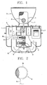
- Figure 1 is a sectional view illustrating a conventional electrodeless lighting system
- Figure 2 is an enlarged sectional view illustrating a bulb of an electrodeless bulb assembly of Figure 1.
- a conventional electrodeless lighting system includes a casing 1; a high-tension generator 2 mounted inside the casing 1, and for generating a high tension; a microwave generator 3 mounted inside the casing 1 at a certain interval between itself and the high-tension generator 2, and for generating a microwave; a waveguide 4 for guiding a microwave generated at the microwave generator 3; a resonator 5 installed at the outside of the casing 1 so as to communicate with the waveguide 4, and generating a high intensity electromagnet field by exciting the microwave guided thereto through the waveguide 4; an electrodeless bulb assembly 6 rotatably mounted inside the resonator 5, and including a bulb in which a luminescent material forms a plasma thereby generating light; a mirror 7 positioned at a lower surface of the electrodeless bulb assembly 6, and for upwardly reflecting the light emitted from the electrodeless bulb assembly 6; and a reflector 8 for concentrating light generated at the electrodeless bulb assembly 6, and upwardly reflecting the light.
- a first driving motor 9 for rotating the electrodeless bulb assembly 6 is installed, and a rotation shaft 9a of the first driving motor 9 is connected with a shaft portion 6a of the electrodeless bulb assembly 6 by a connecting shaft 9b.
- a cooling fan 11 and a second driving motor 12 for driving the cooling fan 11 are mounted in order to cool the heat generated at the high tension generator 2 and the microwave generator 3.
- an air duct 13 for guiding external air to the high-tension generator 2 and the microwave generator 3 is provided.
- the electrodeless bulb assembly 6 consists of a transparent bulb 6b filled with a luminescent material, and a shaft portion 6a extended from the bulb 6b so as to be connected with the connecting shaft 9b.
- a high tension is generated at the high-tension generator 2, and a microwave is generated at a microwave generator by the high tension generated from the high-tension generator 2.
- the microwave is transmitted to a resonator 5 through a waveguide 4 and distributes a high intensity electromagnetic field at the resonator.
- the luminescent material within the electrodeless bulb 6b is discharged by the electromagnetic field, and simultaneously gasified, generating a plasma.
- the light which is emitted when the plasma is generated at the electrodeless bulb 6b is upwardly reflected by the mirror 7 and the reflector 8.
- the electrodeless bulb assembly has oniy one buib, so oniy one beam is emitted.
- an object of the present invention is to provide an electrodeless lighting system capable of selectively illuminating one of a plurality of electrodeless bulbs installed inside the resonator.
- an electrodeless lighting system including a high-tension generator mounted at a casing, and for generating a high tension; a microwave generator mounted at the casing at a certain interval between itself and the high-tension generator so as to generate a microwave by the high-tension generated at the high-tension generator; a waveguide installed at the casing, and for guiding the microwave generated at the microwave generator; a resonator communicating with the waveguide so as to generate a high intensity electromagnetic field by exciting the microwave guided thereto through the waveguide; an electrodeless bulb assembly rotatably mounted inside the resonator, and including a plurality of bulbs, for generating light by forming a plasma; and a stud for controlling an impedance, which is installed inside the resonator, and selectively illuminating one of a plurality of bulbs of the electrodeless bulb assembly.
- Figure 2 is an enlarged view illustrating an electrodeless bulb assembly of Figure 1
- Figure 3 is a sectional view illustrating an electrodeless lighting system according to the present invention
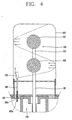
- Figure 4 is an enlarged view of a main part extracted from Figure 3.
- an electrodeless lighting system includes a high-tension generator 120 mounted at a casing 110, and for generating a high tension; a microwave generator 130 mounted at the casing 110 at a certain interval between itself and the high-tension generator 120 so as to generate a microwave by the high tension generated at the high-tension generator 120; a waveguide 140 installed at the casing 110, and for guiding the microwave generated from the microwave generator 130; a resonator 150 communicating with the waveguide so as to generate a high intensity electromagnetic field by exciting the microwave guided thereto through the waveguide 140; an electrodeless bulb assembly 160 rotatably mounted inside the resonator 150, and including a plurality of bulbs, and emitting light by forming a plasma; and a stud 170 for controlling an impedance (hereinafter, referred to as 'stud'), installed inside the resonator 150, and selectively illuminating one of a plurality of bulbs of the electrodeless bulb assembly 160.
- 'stud' an impedance
- a mirror 7 is positioned at the lower portion of the electrodeless bulb assembly 160 to upwardly reflect the light emitted at the electrodeless bulb assembly 160.
- a reflector 8 for encompassing the resonator 150 and for collecting light generated at the electrodeless bulb assembly 160 and upwardly reflecting the light is installed at an upper portion of the waveguide 140.
- a first driving motor 9 for rotating the electrodeless bulb assembly 160 is installed, and a rotation shaft 9a of the first driving motor 9 is connected with a first shaft portion 161 of the electrodeless bulb assembly 160 by a connecting shaft 9b.
- a cooiing fan 11 and a second driving motor 12 for driving the cooling fan are mounted inside the casing 110.
- an air duct 13 for guiding air to the high-tension generator 120 and the microwave generator 130 is provided.
- the electrodeless bulb assembly 160 includes a first shaft portion 161 connected with the rotation shaft 9a of the driving motor 9 through the connecting shaft 9b; a first transparent bulb 162 formed at an upper portion of the first shaft portion 161, and filled with a first luminescent material; a second transparent bulb 163 positioned at an upper part of the first bulb 162, and filled with a second luminescent material; and a second shaft portion 164 connecting the first bulb 162 and the second bulb 163.
- a luminescent material within the bulb 162, 163 of the electrodeless bulb assembly 160 contains a material such as metal, that is, a halide compound, sulfur or selenium, which emits light with forming a plasma; inactive gas such as argon, xenon and krypton for forming a plasma at an initial stage of light-emitting; and an addition for making lighting easy by activating an initial electric discharge or for controlling spectrum of the generated light and the like.
- the stud 170 is vertically moved by the stud moving means, and is detachably/attachably installed inside the resonator 150,
- the stud moving means includes a frame 181 installed at an upper portion of the waveguide 140, and having an upper surface where a screw hole 181 a is formed; and a moving member 182 having an upper portion to which the stud 170 is fixed, and a lower portion where a screw 182a coupled to the screw hole 181 a is formed.
- a microwave is generated at the microwave generator 130 by a high-tension generated at the high-tension generator 120.
- the microwave is transmitted to the resonator 150 through the waveguide 140, and distributes a high intensity electromagnetic field.
- the luminescent material within the electrodeless bulb assembly 160 is discharged by the electromagnetic field, and simultaneously gasified, generating a plasma.
- the distribution of intensity of the electromagnetic field which is distributed in the resonator 50 is changed.
- one of a luminescent material within the first bulb 162 and a luminescent material within the second bulb 163 is selectively discharged, and simultaneously gasified, generating a plasma.
- the first bulb 162 is filled with a luminescent material emitting a high color temperature
- the second bulb 163 is filled with a luminescent material emitting a low color temperature.
- the position of the stud 170 is changed so that intensity of the electromagnetic field has high distribution in the resonator 50, thereby emitting white light or blue light, to feel cool.
- the position of the stud 170 is changed so that the intensity of the electromagnetic field has low distribution in the resonator 50, thereby emitting red light, to feel warm.
- the light emitted while a plasma is generated at the electrodeless bulb assembly 160 is upwardly reflected by the mirror 7 and the reflector 8.
- the electrodeless bulb assembly 160 is cooled.
- the second driving motor 12 is operated to rotate the cooling fan 11, external air is flowed through the air duct 13 so that the high-tension generator 120 and the microwave generator 130 are cooled.
- Figure 5 is a sectional view illustrating a different embodiment of an electrodeless lighting system according to the present invention.
- an electrodeless bulb assembly 260 (261, 262) is rotatably mounted inside the resonator 250 so as to generate light by forming a plasma, and a plurality of studs 270, 271 whose sizes and heights are different from each other is installed inside the resonator 250.
- a microwave is generated at a microwave generator 130 by a high tension generated at the high-tension generator.
- the microwave is transmitted to the resonator 250 through the waveguide 240, to distribute a high intensity electromagnetic field.
- the distribution of the intensity of the electromagnetic field distributed in the resonator 250 is changed according to each stud 270, 271.
- a luminescent material within one of a plurality of bulbs 261, 262 is selectively discharged, and simultaneously gasified, generating a plasma.
- the light emitted while the plasma is generated at the electrodeless bulb assembly 160 is upwardly reflected by a mirror (not shown) and a refiector,
- a position of a stud mounted inside the resonator can be changed, the size of the stud mounted inside the resonator can be changed, or the number of studs can be changed thereby changing distribution of intensity of the electromagnetic field distributed in the resonator, so as to selectively illuminate one of the luminescent materials within the first and second bulbs according to the taste of a user or a season. Accordingly, in the present invention, desired light of various kinds can be emitted.
Landscapes
- Physics & Mathematics (AREA)
- Engineering & Computer Science (AREA)
- Plasma & Fusion (AREA)
- Electromagnetism (AREA)
- Non-Portable Lighting Devices Or Systems Thereof (AREA)
- Discharge Lamps And Accessories Thereof (AREA)
- Circuit Arrangements For Discharge Lamps (AREA)
Applications Claiming Priority (2)
| Application Number | Priority Date | Filing Date | Title |
|---|---|---|---|
| KR2003061446 | 2003-09-03 | ||
| KR10-2003-0061446A KR100531909B1 (ko) | 2003-09-03 | 2003-09-03 | 무전극 조명기기의 발광장치 |
Publications (2)
| Publication Number | Publication Date |
|---|---|
| EP1519405A2 true EP1519405A2 (de) | 2005-03-30 |
| EP1519405A3 EP1519405A3 (de) | 2006-05-10 |
Family
ID=34192218
Family Applications (1)
| Application Number | Title | Priority Date | Filing Date |
|---|---|---|---|
| EP03293315A Withdrawn EP1519405A3 (de) | 2003-09-03 | 2003-12-23 | Elektrodenloses Beleuchtungssystem |
Country Status (5)
| Country | Link |
|---|---|
| US (1) | US6954037B2 (de) |
| EP (1) | EP1519405A3 (de) |
| JP (1) | JP3892853B2 (de) |
| KR (1) | KR100531909B1 (de) |
| CN (1) | CN1317734C (de) |
Families Citing this family (10)
| Publication number | Priority date | Publication date | Assignee | Title |
|---|---|---|---|---|
| KR100831209B1 (ko) * | 2005-03-14 | 2008-05-21 | 엘지전자 주식회사 | 무전극 조명기기의 공진기 구조 |
| KR100778486B1 (ko) * | 2005-06-10 | 2007-11-21 | 엘지전자 주식회사 | 무전극 전구 및 이를 이용한 무전극 조명기기 |
| KR20070039304A (ko) * | 2005-10-07 | 2007-04-11 | 엘지전자 주식회사 | 초기 점등 수단을 구비한 중출력 무전극 조명기기 |
| CN101243541B (zh) * | 2006-03-14 | 2010-10-06 | Lg电子株式会社 | 用于防止等离子发光系统的灯泡内材料泄漏的装置 |
| DE102008011526A1 (de) * | 2008-02-28 | 2009-09-03 | Leica Microsystems (Schweiz) Ag | Beleuchtungseinrichtung mit verbesserter Lebensdauer für ein Mikroskop |
| JP5239908B2 (ja) * | 2009-01-29 | 2013-07-17 | セイコーエプソン株式会社 | 光源装置、プロジェクター |
| KR101432594B1 (ko) * | 2009-07-13 | 2014-08-21 | 엘지전자 주식회사 | 무전극 조명기기 |
| KR101332331B1 (ko) * | 2012-07-13 | 2013-11-22 | 태원전기산업 (주) | 초고주파 발광 램프 장치 |
| CN108538701B (zh) * | 2018-05-15 | 2020-06-26 | 北京航空航天大学 | 增强微波与等离子体耦合率的谐振腔及微波等离子体装置 |
| CN108538696B (zh) * | 2018-05-15 | 2020-04-07 | 北京航空航天大学 | 微波与等离子体耦合率可调的谐振腔及微波等离子体装置 |
Citations (3)
| Publication number | Priority date | Publication date | Assignee | Title |
|---|---|---|---|---|
| JPH1167159A (ja) * | 1997-08-26 | 1999-03-09 | Matsushita Electric Works Ltd | 無電極hidランプ及びその装置 |
| JP2003022787A (ja) * | 2001-07-09 | 2003-01-24 | Matsushita Electric Works Ltd | マイクロ波無電極放電灯装置 |
| US20030098639A1 (en) * | 2001-11-23 | 2003-05-29 | Lg Electronics Inc. | Lighting apparatus using microwave |
Family Cites Families (11)
| Publication number | Priority date | Publication date | Assignee | Title |
|---|---|---|---|---|
| US4933602A (en) * | 1987-03-11 | 1990-06-12 | Hitachi, Ltd. | Apparatus for generating light by utilizing microwave |
| DE3932030A1 (de) * | 1989-09-26 | 1991-04-04 | Philips Patentverwaltung | Hochdruckgasentladungslampe |
| US6031333A (en) * | 1996-04-22 | 2000-02-29 | Fusion Lighting, Inc. | Compact microwave lamp having a tuning block and a dielectric located in a lamp cavity |
| JP3580205B2 (ja) * | 2000-01-18 | 2004-10-20 | ウシオ電機株式会社 | 電磁エネルギー励起点光源ランプ装置 |
| JP3400796B2 (ja) * | 2000-10-30 | 2003-04-28 | 松下電器産業株式会社 | 無電極放電ランプ装置 |
| KR100367612B1 (ko) * | 2000-12-29 | 2003-01-10 | 엘지전자 주식회사 | 다수의 발광부를 갖는 마이크로파 조명 장치 |
| KR100367613B1 (ko) * | 2000-12-29 | 2003-01-10 | 엘지전자 주식회사 | 다수의 전구를 가진 마이크로파 조명 장치 |
| KR100393787B1 (ko) * | 2001-01-08 | 2003-08-02 | 엘지전자 주식회사 | 마이크로파를 이용한 조명장치 |
| KR100393817B1 (ko) * | 2001-09-27 | 2003-08-02 | 엘지전자 주식회사 | 무전극 조명기기 |
| KR20030026806A (ko) * | 2001-09-28 | 2003-04-03 | 주식회사 엘지이아이 | 마이크로파의 누출을 차단하는 장치 및 그 방법 |
| KR100442397B1 (ko) * | 2002-01-17 | 2004-07-30 | 엘지전자 주식회사 | 무전극 조명기기의 점등 촉진구조 |
-
2003
- 2003-09-03 KR KR10-2003-0061446A patent/KR100531909B1/ko not_active Expired - Fee Related
- 2003-12-23 EP EP03293315A patent/EP1519405A3/de not_active Withdrawn
-
2004
- 2004-01-06 CN CNB2004100000563A patent/CN1317734C/zh not_active Expired - Fee Related
- 2004-01-29 US US10/768,625 patent/US6954037B2/en not_active Expired - Fee Related
- 2004-02-23 JP JP2004046756A patent/JP3892853B2/ja not_active Expired - Fee Related
Patent Citations (3)
| Publication number | Priority date | Publication date | Assignee | Title |
|---|---|---|---|---|
| JPH1167159A (ja) * | 1997-08-26 | 1999-03-09 | Matsushita Electric Works Ltd | 無電極hidランプ及びその装置 |
| JP2003022787A (ja) * | 2001-07-09 | 2003-01-24 | Matsushita Electric Works Ltd | マイクロ波無電極放電灯装置 |
| US20030098639A1 (en) * | 2001-11-23 | 2003-05-29 | Lg Electronics Inc. | Lighting apparatus using microwave |
Also Published As
| Publication number | Publication date |
|---|---|
| CN1591768A (zh) | 2005-03-09 |
| EP1519405A3 (de) | 2006-05-10 |
| KR100531909B1 (ko) | 2005-11-29 |
| CN1317734C (zh) | 2007-05-23 |
| US20050062426A1 (en) | 2005-03-24 |
| US6954037B2 (en) | 2005-10-11 |
| JP2005079089A (ja) | 2005-03-24 |
| KR20050023887A (ko) | 2005-03-10 |
| JP3892853B2 (ja) | 2007-03-14 |
Similar Documents
| Publication | Publication Date | Title |
|---|---|---|
| JP4091596B2 (ja) | 無電極ランプシステム | |
| US6954037B2 (en) | Electrodeless lighting system | |
| KR20040057161A (ko) | 브롬화주석을 이용한 무전극 조명 시스템 | |
| KR100531908B1 (ko) | 무전극 조명기기의 마이크로파 집속장치 | |
| US6608443B1 (en) | Lighting apparatus using microwave energy | |
| US6784619B2 (en) | Electrodeless lighting system | |
| JP2006261098A (ja) | 無電極照明機器 | |
| KR20030080747A (ko) | 무전극 조명기기의 무전극 전구 | |
| KR100367612B1 (ko) | 다수의 발광부를 갖는 마이크로파 조명 장치 | |
| KR100343699B1 (ko) | 플라즈마 램프의 구조 | |
| KR20020054161A (ko) | 마이크로파 조명장치의 광 반사 구조 | |
| KR100393788B1 (ko) | 마이크로파를 이용한 조명장치 및 도파관 구조 | |
| KR100739161B1 (ko) | 전구 편심형 무전극 조명기기 | |
| KR100531907B1 (ko) | 무전극 램프의 무전극 전구 | |
| KR20040062004A (ko) | 무전극 조명기기 | |
| KR100414089B1 (ko) | 마이크로파를 이용한 조명시스템 | |
| KR100414090B1 (ko) | 마이크로파를 이용한 조명시스템 | |
| KR100396770B1 (ko) | 마그네트론 일체형 마이크로파 조명 장치 | |
| KR100414091B1 (ko) | 마이크로파를 이용한 조명시스템 | |
| KR100533049B1 (ko) | 무전극 램프의 무전극 전구 | |
| KR20030008348A (ko) | 마이크로파를 이용한 조명시스템 | |
| KR20030000525A (ko) | 마이크로파를 이용한 조명시스템의 냉각장치 | |
| KR20030000526A (ko) | 마이크로파를 이용한 조명시스템의 냉각장치 | |
| KR20030092168A (ko) | 무전극 램프의 반사장치 | |
| KR20030005789A (ko) | 마이크로파를 이용한 조명시스템 |
Legal Events
| Date | Code | Title | Description |
|---|---|---|---|
| PUAI | Public reference made under article 153(3) epc to a published international application that has entered the european phase |
Free format text: ORIGINAL CODE: 0009012 |
|
| AK | Designated contracting states |
Kind code of ref document: A2 Designated state(s): AT BE BG CH CY CZ DE DK EE ES FI FR GB GR HU IE IT LI LU MC NL PT RO SE SI SK TR |
|
| AX | Request for extension of the european patent |
Extension state: AL LT LV MK |
|
| PUAL | Search report despatched |
Free format text: ORIGINAL CODE: 0009013 |
|
| AK | Designated contracting states |
Kind code of ref document: A3 Designated state(s): AT BE BG CH CY CZ DE DK EE ES FI FR GB GR HU IE IT LI LU MC NL PT RO SE SI SK TR |
|
| AX | Request for extension of the european patent |
Extension state: AL LT LV MK |
|
| 17P | Request for examination filed |
Effective date: 20061013 |
|
| AKX | Designation fees paid |
Designated state(s): DE FR |
|
| 17Q | First examination report despatched |
Effective date: 20110314 |
|
| STAA | Information on the status of an ep patent application or granted ep patent |
Free format text: STATUS: THE APPLICATION IS DEEMED TO BE WITHDRAWN |
|
| 18D | Application deemed to be withdrawn |
Effective date: 20110726 |