EP1519390A2 - Cryogen-free high temperature superconducting magnet with thermal reservoir - Google Patents
Cryogen-free high temperature superconducting magnet with thermal reservoir Download PDFInfo
- Publication number
- EP1519390A2 EP1519390A2 EP04255756A EP04255756A EP1519390A2 EP 1519390 A2 EP1519390 A2 EP 1519390A2 EP 04255756 A EP04255756 A EP 04255756A EP 04255756 A EP04255756 A EP 04255756A EP 1519390 A2 EP1519390 A2 EP 1519390A2
- Authority
- EP
- European Patent Office
- Prior art keywords
- superconducting magnet
- thermal
- thermal reservoir
- reservoir
- cryogen
- Prior art date
- Legal status (The legal status is an assumption and is not a legal conclusion. Google has not performed a legal analysis and makes no representation as to the accuracy of the status listed.)
- Withdrawn
Links
- 230000000712 assembly Effects 0.000 claims abstract description 9
- 238000000429 assembly Methods 0.000 claims abstract description 9
- 238000001816 cooling Methods 0.000 claims abstract description 7
- 238000000034 method Methods 0.000 claims abstract description 4
- 239000000463 material Substances 0.000 claims description 37
- 238000003384 imaging method Methods 0.000 claims description 12
- 239000004593 Epoxy Substances 0.000 claims description 3
- CERQOIWHTDAKMF-UHFFFAOYSA-M Methacrylate Chemical compound CC(=C)C([O-])=O CERQOIWHTDAKMF-UHFFFAOYSA-M 0.000 claims description 3
- 239000004033 plastic Substances 0.000 claims description 3
- 229920003023 plastic Polymers 0.000 claims description 3
- 229920002635 polyurethane Polymers 0.000 claims description 3
- 239000004814 polyurethane Substances 0.000 claims description 3
- 229920005989 resin Polymers 0.000 claims description 3
- 239000011347 resin Substances 0.000 claims description 3
- 244000043261 Hevea brasiliensis Species 0.000 claims description 2
- 239000011133 lead Substances 0.000 claims description 2
- 229920003052 natural elastomer Polymers 0.000 claims description 2
- 229920001194 natural rubber Polymers 0.000 claims description 2
- 229920003051 synthetic elastomer Polymers 0.000 claims description 2
- 239000005061 synthetic rubber Substances 0.000 claims description 2
- 238000002595 magnetic resonance imaging Methods 0.000 description 18
- XEEYBQQBJWHFJM-UHFFFAOYSA-N Iron Chemical compound [Fe] XEEYBQQBJWHFJM-UHFFFAOYSA-N 0.000 description 12
- 229910052742 iron Inorganic materials 0.000 description 6
- 239000007788 liquid Substances 0.000 description 4
- 229920003319 Araldite® Polymers 0.000 description 3
- 229910052734 helium Inorganic materials 0.000 description 3
- 239000001307 helium Substances 0.000 description 3
- SWQJXJOGLNCZEY-UHFFFAOYSA-N helium atom Chemical compound [He] SWQJXJOGLNCZEY-UHFFFAOYSA-N 0.000 description 3
- RYGMFSIKBFXOCR-UHFFFAOYSA-N Copper Chemical compound [Cu] RYGMFSIKBFXOCR-UHFFFAOYSA-N 0.000 description 2
- 229910052802 copper Inorganic materials 0.000 description 2
- 239000010949 copper Substances 0.000 description 2
- 229910021521 yttrium barium copper oxide Inorganic materials 0.000 description 2
- 229910020073 MgB2 Inorganic materials 0.000 description 1
- 229910001275 Niobium-titanium Inorganic materials 0.000 description 1
- PZKRHHZKOQZHIO-UHFFFAOYSA-N [B].[B].[Mg] Chemical compound [B].[B].[Mg] PZKRHHZKOQZHIO-UHFFFAOYSA-N 0.000 description 1
- DONOEDROFPWYIJ-UHFFFAOYSA-N [Cu]=O.[Ba].[Dy] Chemical compound [Cu]=O.[Ba].[Dy] DONOEDROFPWYIJ-UHFFFAOYSA-N 0.000 description 1
- OSOKRZIXBNTTJX-UHFFFAOYSA-N [O].[Ca].[Cu].[Sr].[Bi] Chemical compound [O].[Ca].[Cu].[Sr].[Bi] OSOKRZIXBNTTJX-UHFFFAOYSA-N 0.000 description 1
- BTGZYWWSOPEHMM-UHFFFAOYSA-N [O].[Cu].[Y].[Ba] Chemical compound [O].[Cu].[Y].[Ba] BTGZYWWSOPEHMM-UHFFFAOYSA-N 0.000 description 1
- 150000001875 compounds Chemical class 0.000 description 1
- 229920001971 elastomer Polymers 0.000 description 1
- 238000009413 insulation Methods 0.000 description 1
- 239000006148 magnetic separator Substances 0.000 description 1
- RJSRQTFBFAJJIL-UHFFFAOYSA-N niobium titanium Chemical compound [Ti].[Nb] RJSRQTFBFAJJIL-UHFFFAOYSA-N 0.000 description 1
- 238000013021 overheating Methods 0.000 description 1
- 230000003094 perturbing effect Effects 0.000 description 1
- 239000005060 rubber Substances 0.000 description 1
- 239000002887 superconductor Substances 0.000 description 1
Images
Classifications
-
- G—PHYSICS
- G01—MEASURING; TESTING
- G01R—MEASURING ELECTRIC VARIABLES; MEASURING MAGNETIC VARIABLES
- G01R33/00—Arrangements or instruments for measuring magnetic variables
- G01R33/20—Arrangements or instruments for measuring magnetic variables involving magnetic resonance
- G01R33/28—Details of apparatus provided for in groups G01R33/44 - G01R33/64
- G01R33/38—Systems for generation, homogenisation or stabilisation of the main or gradient magnetic field
- G01R33/381—Systems for generation, homogenisation or stabilisation of the main or gradient magnetic field using electromagnets
- G01R33/3815—Systems for generation, homogenisation or stabilisation of the main or gradient magnetic field using electromagnets with superconducting coils, e.g. power supply therefor
-
- H—ELECTRICITY
- H01—ELECTRIC ELEMENTS
- H01F—MAGNETS; INDUCTANCES; TRANSFORMERS; SELECTION OF MATERIALS FOR THEIR MAGNETIC PROPERTIES
- H01F6/00—Superconducting magnets; Superconducting coils
- H01F6/04—Cooling
-
- H—ELECTRICITY
- H01—ELECTRIC ELEMENTS
- H01F—MAGNETS; INDUCTANCES; TRANSFORMERS; SELECTION OF MATERIALS FOR THEIR MAGNETIC PROPERTIES
- H01F6/00—Superconducting magnets; Superconducting coils
Definitions
- This invention relates generally to methods and apparatus for cooling a superconducting magnet, and specifically to cooling a magnet used in a magnetic resonance imaging (MRI) system.
- MRI magnetic resonance imaging
- MRI magnetic resonance imaging
- Superconducting MRI systems typically utilize one superconducting magnet, often with multiple coils.
- An imaging volume is provided inside the magnet.
- a person or material is placed into an imaging volume and an image or signal is detected and then processed by a processor, such as a computer.
- the majority of existing superconducting MRI magnets are made of a niobium-titanium material which is cooled to a temperature of 4.2 K with liquid helium. This has the disadvantage of requiring a supply of liquid helium which is expensive and may not be available in underdeveloped countries. Further, in the event of a power failure or a mechanical failure the cooling system, only the latent heat of the helium reserve is available to provide "ride-through" (the period of time from the failure of the cooling mechanism to the loss of superconductivity due to a rise in temperature above the critical temperature of the superconducting material) due to the small heat capacity of the materials in the MRI system.
- a cryogen free superconducting magnet assembly comprising a high T c superconducting magnet and a thermal reservoir in thermal contact with the high T c superconducting magnet, wherein the thermal reservoir comprises a material having a heat capacity of at least about 0.065 J/gK at 25 K.
- a method of cooling a cryogen free superconducting magnet assembly comprising providing a high T c superconducting magnet thermally connected to a thermal reservoir, the thermal reservoir comprising a material having a heat capacity of at least about 0.065 J/gK at 25 K; providing a cryocooler thermally connected to the high T c superconducting magnet, and withdrawing heat from the high T c superconducting magnet without using a cryogen.
- an MRI system comprising a cryogen free superconducting magnet assembly having a high T c superconducting magnet, and a thermal reservoir in thermal contact with the high T c superconducting magnet, the thermal reservoir comprising a material having a heat capacity of at least about 0.065 J/gK at 25 K, wherein an imaging volume is formed inside the superconducting magnet assembly and a cryocooler thermally connected to the thermal reservoir.
- an MRI system comprising a first cryogen free superconducting magnet assembly having a first high T c superconducting magnet, and a first thermal reservoir in thermal contact with the first high T c superconducting magnet, the first thermal reservoir comprising a material having a heat capacity of at least about 0.065 J/gK at 25 K; and a second cryogen free superconducting magnet assembly having a second high T c superconducting magnet, and a second thermal reservoir in thermal contact with the second high T c superconducting magnet, the second thermal reservoir comprising a material having a heat capacity of at least about 0.065 J/gK at 25 K, such that an imaging volume is formed between the first and second assemblies.
- an MRI system comprising a first cryogen free superconducting magnet assembly having a first high T c superconducting magnet; a second cryogen free superconducting magnet assembly having a second high T c superconducting magnet; and a thermal reservoir in thermal contact with the first and second high T c superconducting magnets, the thermal reservoir comprising a material having a heat capacity of at least about 0.065 J/gK at 25 K, such that an imaging volume is formed between the first and second assemblies.
- liquid cryogens can be eliminated from superconducting systems while maintaining ride-through capability when a thermal reservoir made of a high heat capacity material surrounds or is placed in thermal contact with the superconducting magnets cooled with a cryocooler.
- a thermal reservoir made of a high heat capacity material surrounds or is placed in thermal contact with the superconducting magnets cooled with a cryocooler.
- high T c superconducting coils capable of operating at temperatures above 20 K are in thermal contact with a thermal reservoir fabricated from a material with a high heat capacity.
- high T c superconducting coils are surrounded by the thermal reservoir.
- Example high T c superconducting materials include, but are not limited to, DBCO (Dysprosium Barium Copper Oxide), YBCO (Yttrium Barium Copper Oxide), BSCCO (Bismuth Strontium Calcium Copper Oxide), and MgB 2 (Magnesium Diboride).
- the critical temperature of a superconductor refers to the temperature at which the superconducting material losses superconductivity.
- the critical temperature is the temperature above which the magnet can no longer operate at its rated magnetic field.
- the rated magnetic field may be unique to each design and is typically a function of magnet size, shape and operating temperature.
- the thermal reservoir material has a heat capacity of at least about 0.065 J/gK at 25 K. More preferably, the thermal reservoir material has a heat capacity of at least about 0.10 J/gK at 25 K. Alternatively, the thermal reservoir material may have a minimum enthalpy change of at least about 0.65 J/g between 20 K and 30 K. Preferably, the thermal reservoir material has a minimum enthalpy change of at least about 1.55 J/g between 20 K and 30 K.
- the thermal capacity of the thermal reservoir is preferably greater than about 9 x 10 5 J.
- the thermal mass of the thermal reservoir to provide this thermal capacity will vary depending on the heat capacity of the thermal reservoir material. However, the thermal mass is typically greater than about 525 kg.
- the thermal reservoir has sufficient thermal mass to provide ride-through of at least 5 hours in the event of loss of power. More preferably, the thermal reservoir has sufficient thermal mass to provide ride-through of at least 10 hours.
- Suitable materials for the thermal reservoir of the present embodiment include ice, epoxy, methacrylate, polyurethane, synthetic rubber, natural rubber, plastic, resin, and lead.
- Preferred materials include ice, Araldite® and Glyptal®.
- Araldite® is a family of materials which span epoxy, methacrylate, and polyurethane.
- Glyptal® is a resin based plastic. Heat capacity and enthalpy change data for these materials are summarized in the table below.
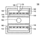
- the figure illustrates a cross section of a cylindrical MRI system 100 according to a second embodiment of the invention.
- the MRI system 100 includes a cryogen free superconducting magnet assembly 110 according to the first preferred embodiment of the invention.
- the cryogen free superconducting magnet assembly 110 includes at least one superconducting magnet 114.
- the cryogen free superconducting magnet assemblies 110 typically include a plurality of superconducting magnets 114.
- the superconducting magnets 114 are essentially completely surrounded by the thermal reservoir 112.
- the superconducting magnets 114 are enclosed from all sides (including top and bottom), having only openings for leads and supports. However, the superconducting magnets 114 need not be entirely surrounded. The superconducting magnets 114 are thermally connected to the thermal reservoir 112.
- a cryocooler 120 may be thermally connected to the thermal reservoir 112.
- the cyrocooler 120 may be thermally connected to the superconducting magnets 114 as well.
- the thermal connection between the cryocooler 120 and the thermal reservoir 112 is made using a thermal connector 170 fabricated from a high thermal conductivity material.
- the thermal connector 170 is fabricated of copper.
- any material with sufficient thermal conductivity to prevent the superconducting magnets 114 from overheating may be used.
- the thermal connection between the cryocooler 120 and the thermal reservoir 112 is made using a heat pipe.
- a heat pipe is an enclosed container made of a material with high conductivity and having a small amount of liquid cryogen inside.
- the heat pipe is configured so that cryogen pools at the end thermally connected to the thermal reservoir 112.
- the other end is thermally connected to the cryocooler 120.
- the cryogen absorbs heat, it evaporates, carrying heat to the end thermally connected to the cryocooler 120.
- the cryogen vapor condenses and runs down the sides of the heat pipe, available to start the cycle again.
- the heat pipe may be used in combination with a copper rod to form a compound thermal connector 170.
- the MRI system 100 includes one cryogen free superconducting magnet assembly 110.
- the cryogen free superconducting magnet assembly 110 is assembled such that an imaging volume 150 is formed therein.
- gradient coils 140 which allow the imaging of a specific volume of matter and passive iron shields 130 which reduce the perturbing effects of nearby magnetized objects.
- the thermal reservoir 112 is located between the gradient coils 140 and the passive iron shield 130 within the vacuum chamber 160.
- the cryogen free superconducting magnet assembly 110 is enclosed in a vacuum chamber 160. The vacuum chamber 160 isolates the thermal reservoir 112 from the rest of the MRI system 100 and the ambient, thus providing insulation.
- the thermal reservoir 112 is located outside of the passive iron shield 130 but still within the vacuum chamber 160. That is, a particular superconducting MRI design might require that that the space between the passive iron shield 130 and the superconducting magnet 114 be relatively small, such that it is too small for an effective thermal mass for a thermal reservoir 112. Thus, in this embodiment, the thermal reservoir 112 is located beyond the passive iron shield 130 but in thermal contact with the superconducting magnets 114 via a thermal connector 170.
- the thermal connector 170 may be a rod or block of a material of sufficient thermal conductivity and/or a heat pipe. Further, the thermal connector 170 may pass through the passive iron shield 130 or go around it to contact the superconducting magnets 114. In one aspect of the invention, one thermal connector 170 may be used to connect the cryocooler 120 to the thermal reservoir 112 and the superconducting magnets 114. In another aspect of the invention, separate thermal connectors 170 may used to connect the cryocooler 120 to the thermal reservoir 112 and the cryocooler 120 to the superconducting magnets 114.
- the MRI system 100 includes two cryogen free superconducting magnet assemblies 110.
- each cryogen free superconducting magnet assembly 110 includes superconducting magnets 114.
- each cryogen free superconducting magnet assembly 100 includes a respective thermal reservoir 112.
- both cryogen free superconducting magnet assemblies 110 are thermally connected to a single thermal reservoir 112.
- the superconducting magnet assemblies 110 may be used in other magnetic systems.
- additional embodiments of the invention include magnetic separators, motors and generators.
Landscapes
- Physics & Mathematics (AREA)
- Engineering & Computer Science (AREA)
- Power Engineering (AREA)
- Electromagnetism (AREA)
- Condensed Matter Physics & Semiconductors (AREA)
- General Physics & Mathematics (AREA)
- Magnetic Resonance Imaging Apparatus (AREA)
- Containers, Films, And Cooling For Superconductive Devices (AREA)
Abstract
A cryogen free superconducting magnet assembly having a high Tc
superconducting magnet and a thermal reservoir in thermal contact with the
high Tc superconducting magnet. A method of cooling a cryogen free
superconducting magnet assembly and an MRI system having cryogen free
superconducting magnet assemblies.
Description
- This invention relates generally to methods and apparatus for cooling a superconducting magnet, and specifically to cooling a magnet used in a magnetic resonance imaging (MRI) system.
- There are various magnetic imaging systems which utilize superconducting magnets. One example of an imaging system is a magnetic resonance imaging (MRI) system. MRI systems are used to image a portion of a patient's body.
- Superconducting MRI systems typically utilize one superconducting magnet, often with multiple coils. An imaging volume is provided inside the magnet. A person or material is placed into an imaging volume and an image or signal is detected and then processed by a processor, such as a computer.
- The majority of existing superconducting MRI magnets are made of a niobium-titanium material which is cooled to a temperature of 4.2 K with liquid helium. This has the disadvantage of requiring a supply of liquid helium which is expensive and may not be available in underdeveloped countries. Further, in the event of a power failure or a mechanical failure the cooling system, only the latent heat of the helium reserve is available to provide "ride-through" (the period of time from the failure of the cooling mechanism to the loss of superconductivity due to a rise in temperature above the critical temperature of the superconducting material) due to the small heat capacity of the materials in the MRI system.
- In accordance with one preferred aspect of the present invention, there is provided a cryogen free superconducting magnet assembly comprising a high Tc superconducting magnet and a thermal reservoir in thermal contact with the high Tc superconducting magnet, wherein the thermal reservoir comprises a material having a heat capacity of at least about 0.065 J/gK at 25 K.
- In accordance with one preferred aspect of the present invention, there is provided a method of cooling a cryogen free superconducting magnet assembly comprising providing a high Tc superconducting magnet thermally connected to a thermal reservoir, the thermal reservoir comprising a material having a heat capacity of at least about 0.065 J/gK at 25 K; providing a cryocooler thermally connected to the high Tc superconducting magnet, and withdrawing heat from the high Tc superconducting magnet without using a cryogen.
- In accordance with one preferred aspect of the present invention, there is provided an MRI system comprising a cryogen free superconducting magnet assembly having a high Tc superconducting magnet, and a thermal reservoir in thermal contact with the high Tc superconducting magnet, the thermal reservoir comprising a material having a heat capacity of at least about 0.065 J/gK at 25 K, wherein an imaging volume is formed inside the superconducting magnet assembly and a cryocooler thermally connected to the thermal reservoir.
- In accordance with one preferred aspect of the present invention, there is provided an MRI system comprising a first cryogen free superconducting magnet assembly having a first high Tc superconducting magnet, and a first thermal reservoir in thermal contact with the first high Tc superconducting magnet, the first thermal reservoir comprising a material having a heat capacity of at least about 0.065 J/gK at 25 K; and a second cryogen free superconducting magnet assembly having a second high Tc superconducting magnet, and a second thermal reservoir in thermal contact with the second high Tc superconducting magnet, the second thermal reservoir comprising a material having a heat capacity of at least about 0.065 J/gK at 25 K, such that an imaging volume is formed between the first and second assemblies.
- In accordance with one preferred aspect of the present invention, there is provided an MRI system comprising a first cryogen free superconducting magnet assembly having a first high Tc superconducting magnet; a second cryogen free superconducting magnet assembly having a second high Tc superconducting magnet; and a thermal reservoir in thermal contact with the first and second high Tc superconducting magnets, the thermal reservoir comprising a material having a heat capacity of at least about 0.065 J/gK at 25 K, such that an imaging volume is formed between the first and second assemblies.
- The invention will now be described in greater detail, by way of example, with reference to the drawings, the single figure of which is a schematic illustration of an MRI according to a first preferred embodiment of the present invention.
- The present inventors have realized that liquid cryogens can be eliminated from superconducting systems while maintaining ride-through capability when a thermal reservoir made of a high heat capacity material surrounds or is placed in thermal contact with the superconducting magnets cooled with a cryocooler. By using a material with a heat capacity, and a preferably moderate amount of material, enough thermal mass is available to provide adequate ride-through in the event of a power failure. This is particularly advantageous for operation in underdeveloped countries or remote regions where cryogens are often expensive or unavailable.
- A cryogen free superconducting magnet assembly according to one preferred embodiment of the invention will now be described. In this embodiment, high Tc superconducting coils capable of operating at temperatures above 20 K are in thermal contact with a thermal reservoir fabricated from a material with a high heat capacity. Preferably, high Tc superconducting coils are surrounded by the thermal reservoir. Example high Tc superconducting materials include, but are not limited to, DBCO (Dysprosium Barium Copper Oxide), YBCO (Yttrium Barium Copper Oxide), BSCCO (Bismuth Strontium Calcium Copper Oxide), and MgB2 (Magnesium Diboride).
- Conventionally, the critical temperature of a superconductor refers to the temperature at which the superconducting material losses superconductivity. However, for the purposes of this specification, the critical temperature is the temperature above which the magnet can no longer operate at its rated magnetic field. The rated magnetic field may be unique to each design and is typically a function of magnet size, shape and operating temperature.
- Preferably, the thermal reservoir material has a heat capacity of at least about 0.065 J/gK at 25 K. More preferably, the thermal reservoir material has a heat capacity of at least about 0.10 J/gK at 25 K. Alternatively, the thermal reservoir material may have a minimum enthalpy change of at least about 0.65 J/g between 20 K and 30 K. Preferably, the thermal reservoir material has a minimum enthalpy change of at least about 1.55 J/g between 20 K and 30 K.
- The thermal capacity of the thermal reservoir is preferably greater than about 9 x 10⁵ J. The thermal mass of the thermal reservoir to provide this thermal capacity will vary depending on the heat capacity of the thermal reservoir material. However, the thermal mass is typically greater than about 525 kg. Preferably, the thermal reservoir has sufficient thermal mass to provide ride-through of at least 5 hours in the event of loss of power. More preferably, the thermal reservoir has sufficient thermal mass to provide ride-through of at least 10 hours.
- Suitable materials for the thermal reservoir of the present embodiment include ice, epoxy, methacrylate, polyurethane, synthetic rubber, natural rubber, plastic, resin, and lead. Preferred materials include ice, Araldite® and Glyptal®. Araldite® is a family of materials which span epoxy, methacrylate, and polyurethane. Glyptal® is a resin based plastic. Heat capacity and enthalpy change data for these materials are summarized in the table below.
Material Specific heat (J/g-K) Enthalpy (J/g) ΔH (J/g) Mass (kg) (10 Hr ride through) 20 K 25 K 30 K 20 K 25 K 30 K 20-30 K Ice 0.114 0.17 0.229 0.615 2.33 1.715 525 Araldite® 0.081 0.135 0.608 1.688 1.080 833 Lead 0.05 0.068 0.079 0.368 0.672 1.042 0.674 1335 Rubber 0.113 0.155 0.196 0.77 1.44 2.32 1.55 581 Glyptal® 0.67 1.3 2.2 1.53 588 - The figure illustrates a cross section of a
cylindrical MRI system 100 according to a second embodiment of the invention. In the figure, the axis of the cylinder runs in the horizontal direction in the plane of the paper. TheMRI system 100 includes a cryogen freesuperconducting magnet assembly 110 according to the first preferred embodiment of the invention. The cryogen freesuperconducting magnet assembly 110 includes at least onesuperconducting magnet 114. However, the cryogen freesuperconducting magnet assemblies 110 typically include a plurality ofsuperconducting magnets 114. In a preferred embodiment of the invention, thesuperconducting magnets 114 are essentially completely surrounded by thethermal reservoir 112. That is, to ensure a ride though of at least 5 hours and preferably 10 hours, thesuperconducting magnets 114 are enclosed from all sides (including top and bottom), having only openings for leads and supports. However, thesuperconducting magnets 114 need not be entirely surrounded. Thesuperconducting magnets 114 are thermally connected to thethermal reservoir 112. - To remove heat generated during use of the
superconducting magnets 114, acryocooler 120 may be thermally connected to thethermal reservoir 112. Optionally, thecyrocooler 120 may be thermally connected to thesuperconducting magnets 114 as well. Preferably, the thermal connection between thecryocooler 120 and thethermal reservoir 112 is made using athermal connector 170 fabricated from a high thermal conductivity material. Typically, thethermal connector 170 is fabricated of copper. However, any material with sufficient thermal conductivity to prevent thesuperconducting magnets 114 from overheating may be used. - In another aspect of the invention, the thermal connection between the
cryocooler 120 and thethermal reservoir 112 is made using a heat pipe. A heat pipe is an enclosed container made of a material with high conductivity and having a small amount of liquid cryogen inside. The heat pipe is configured so that cryogen pools at the end thermally connected to thethermal reservoir 112. The other end is thermally connected to thecryocooler 120. As the cryogen absorbs heat, it evaporates, carrying heat to the end thermally connected to thecryocooler 120. As heat is withdrawn, the cryogen vapor condenses and runs down the sides of the heat pipe, available to start the cycle again. If desired, the heat pipe may be used in combination with a copper rod to form a compoundthermal connector 170. - The
MRI system 100 according to a preferred embodiment of the invention includes one cryogen freesuperconducting magnet assembly 110. The cryogen freesuperconducting magnet assembly 110 is assembled such that animaging volume 150 is formed therein. Also preferably included in theMRI system 100 aregradient coils 140 which allow the imaging of a specific volume of matter andpassive iron shields 130 which reduce the perturbing effects of nearby magnetized objects. In one embodiment of the invention, thethermal reservoir 112 is located between thegradient coils 140 and thepassive iron shield 130 within thevacuum chamber 160. Additionally, the cryogen freesuperconducting magnet assembly 110 is enclosed in avacuum chamber 160. Thevacuum chamber 160 isolates thethermal reservoir 112 from the rest of theMRI system 100 and the ambient, thus providing insulation. - In another preferred embodiment of the invention, the
thermal reservoir 112 is located outside of thepassive iron shield 130 but still within thevacuum chamber 160. That is, a particular superconducting MRI design might require that that the space between thepassive iron shield 130 and thesuperconducting magnet 114 be relatively small, such that it is too small for an effective thermal mass for athermal reservoir 112. Thus, in this embodiment, thethermal reservoir 112 is located beyond thepassive iron shield 130 but in thermal contact with thesuperconducting magnets 114 via athermal connector 170. - The
thermal connector 170 may be a rod or block of a material of sufficient thermal conductivity and/or a heat pipe. Further, thethermal connector 170 may pass through thepassive iron shield 130 or go around it to contact thesuperconducting magnets 114. In one aspect of the invention, onethermal connector 170 may be used to connect thecryocooler 120 to thethermal reservoir 112 and thesuperconducting magnets 114. In another aspect of the invention, separatethermal connectors 170 may used to connect thecryocooler 120 to thethermal reservoir 112 and thecryocooler 120 to thesuperconducting magnets 114. - In another preferred embodiment of the invention, the
MRI system 100 includes two cryogen freesuperconducting magnet assemblies 110. In this embodiment of the invention, each cryogen freesuperconducting magnet assembly 110 includessuperconducting magnets 114. In one aspect of this embodiment, each cryogen freesuperconducting magnet assembly 100 includes a respectivethermal reservoir 112. In another aspect of the this embodiment, both cryogen freesuperconducting magnet assemblies 110 are thermally connected to a singlethermal reservoir 112. - In addition to the
MRI system 100 discussed above, thesuperconducting magnet assemblies 110 may be used in other magnetic systems. For example, additional embodiments of the invention include magnetic separators, motors and generators.
Claims (10)
- A cryogen free superconducting magnet assembly (110) comprising:wherein the thermal reservoir (112) comprises a material having a heat capacity of at least about 0.065 J/gK at 25 K.a high Tc superconducting magnet (114); anda thermal reservoir (112) in thermal contact with the high Tc superconducting magnet (114),
- The assembly of claim 2, wherein the reservoir material comprises ice, epoxy, methacrylate, polyurethane, synthetic rubber, natural rubber, plastic, resin, or lead.
- The assembly of claim 1, further comprising a cryocooler (120).
- The assembly of claim 1, wherein the thermal reservoir (112) has a thermal capacity greater than about 9 x 10⁵ J.
- The assembly of claim 4, wherein the thermal reservoir (112) has sufficient mass to provide ride-through of at least 10 hours.
- A method of cooling a cryogen free superconducting magnet assembly (110) comprising:providing a high Tc superconducting magnet (114) in thermal contact with a thermal reservoir (112), the thermal reservoir (112) comprising a material having a heat capacity of at least about 0.065 J/gK at 25 K;providing a cryocooler (120) thermally connected to the high Tc superconducting magnet (114); andwithdrawing heat from the high Tc superconducting magnet (114) without using a cryogen.
- An MRI system (100) comprising:a cryogen free superconducting magnet assembly (110) having a high Tc superconducting magnet (114), and a thermal reservoir (112) in thermal contact with the high Tc superconducting magnet (114), the thermal reservoir (112) comprising a material having a heat capacity of at least about 0.065 J/gK at 25 K, wherein an imaging volume is formed inside the superconducting magnet (114) assembly; anda cryocooler (120) thermally connected to the thermal reservoir (112).
- The MRI system (100) of claim 7, wherein the thermal reservoir (112) substantially surrounds high Tc superconducting magnet (114).
- An MRI system (100) comprising:a first cryogen free superconducting magnet assembly (110) having a first high Tc superconducting magnet (114), and a first thermal reservoir (112) in thermal contact with the first high Tc superconducting magnet (114), the first thermal reservoir (112) comprising a material having a heat capacity of at least about 0.065 J/gK at 25 K; anda second cryogen free superconducting magnet assembly (110) having a second high Tc superconducting magnet (114), and a second thermal reservoir (112) in thermal contact with the second high Tc superconducting magnet (114), the second thermal reservoir (112) comprising a material having a heat capacity of at least about 0.065 J/gK at 25 K, such that an imaging volume is formed between the first and second assemblies.
- An MRI system (100) comprising:a first cryogen free superconducting magnet assembly (110) having a first high Tc superconducting magnet (114);a second cryogen free superconducting magnet assembly (110) having a second high Tc superconducting magnet (114); anda thermal reservoir (112) in thermal contact with the first and second high Tc superconducting magnets (114), the thermal reservoir (112) comprising a material having a heat capacity of at least about 0.065 J/gK at 25 K,such that an imaging volume is formed between the first and second assemblies (110).
Applications Claiming Priority (2)
| Application Number | Priority Date | Filing Date | Title |
|---|---|---|---|
| US10/671,146 US20050062473A1 (en) | 2003-09-24 | 2003-09-24 | Cryogen-free high temperature superconducting magnet with thermal reservoir |
| US671146 | 2003-09-24 |
Publications (1)
| Publication Number | Publication Date |
|---|---|
| EP1519390A2 true EP1519390A2 (en) | 2005-03-30 |
Family
ID=34194841
Family Applications (1)
| Application Number | Title | Priority Date | Filing Date |
|---|---|---|---|
| EP04255756A Withdrawn EP1519390A2 (en) | 2003-09-24 | 2004-09-22 | Cryogen-free high temperature superconducting magnet with thermal reservoir |
Country Status (4)
| Country | Link |
|---|---|
| US (1) | US20050062473A1 (en) |
| EP (1) | EP1519390A2 (en) |
| JP (1) | JP2005101613A (en) |
| CN (1) | CN1601662A (en) |
Cited By (2)
| Publication number | Priority date | Publication date | Assignee | Title |
|---|---|---|---|---|
| US7944208B2 (en) | 2007-11-23 | 2011-05-17 | Paramed Medical Systems, Inc. | Active image area positioning with adjustable patient bench permitting chair-shaped patient transport into and out of an open MRI apparatus system |
| EP3273924B1 (en) * | 2015-03-23 | 2021-05-12 | Advanced Imaging Research, Inc. | Safe infant mr imaging system |
Families Citing this family (16)
| Publication number | Priority date | Publication date | Assignee | Title |
|---|---|---|---|---|
| US7319327B2 (en) * | 2005-11-17 | 2008-01-15 | General Electric Company | Magnetic resonance imaging system with reduced cooling needs |
| US20080209919A1 (en) * | 2007-03-01 | 2008-09-04 | Philips Medical Systems Mr, Inc. | System including a heat exchanger with different cryogenic fluids therein and method of using the same |
| US7449889B1 (en) * | 2007-06-25 | 2008-11-11 | General Electric Company | Heat pipe cooled superconducting magnets with ceramic coil forms |
| GB0805988D0 (en) * | 2008-04-03 | 2008-05-07 | Rolls Royce Plc | A superconducting device |
| MX2012003415A (en) * | 2009-09-21 | 2012-06-19 | Time Medical Holdings Company Ltd | Superconductor rf coil array. |
| EP2519786B1 (en) * | 2009-12-28 | 2019-03-27 | Koninklijke Philips N.V. | Cryo-cooling system with a tubular thermal switch |
| US8598881B2 (en) * | 2011-01-11 | 2013-12-03 | General Electric Company | Magnetic resonance imaging system with thermal reservoir and method for cooling |
| GB2490690B (en) | 2011-05-10 | 2013-11-06 | Siemens Plc | Methods and apparatus for orderly run-down of superconducting magnets |
| CN103077797B (en) * | 2013-01-06 | 2016-03-30 | 中国科学院电工研究所 | For the superconducting magnet system of head imaging |
| JP6458031B2 (en) | 2013-11-13 | 2019-01-23 | コーニンクレッカ フィリップス エヌ ヴェKoninklijke Philips N.V. | Superconducting magnet system having a thermally efficient ride-through system and method for cooling a superconducting magnet system |
| GB2545436B (en) * | 2015-12-15 | 2018-04-11 | Siemens Healthcare Ltd | A cylindrical superconducting magnet with a shield of ferromagnetic material |
| JP7177779B2 (en) * | 2017-02-27 | 2022-11-24 | コーニンクレッカ フィリップス エヌ ヴェ | Cooling of Gradient Coils in Magnetic Resonance Imaging Systems |
| WO2019071091A1 (en) * | 2017-10-06 | 2019-04-11 | Advanced Imaging Research, Inc. | OPTIMIZED INFANT MRI SYSTEM WITH CRYOREFROIDY RF COIL |
| CN111228658B (en) * | 2020-02-19 | 2026-03-20 | 上海联影医疗科技股份有限公司 | A magnetic resonance imaging-guided radiotherapy system |
| US12332330B2 (en) | 2020-02-19 | 2025-06-17 | Shanghai United Imaging Healthcare Co., Ltd. | Systems and methods for diagnosis and image guided therapy with superconducting magnet shielding and providing heat exchange |
| EP3982378A1 (en) * | 2020-10-09 | 2022-04-13 | Koninklijke Philips N.V. | Cryogen-free superconducting magnet system |
Family Cites Families (10)
| Publication number | Priority date | Publication date | Assignee | Title |
|---|---|---|---|---|
| US4766741A (en) * | 1987-01-20 | 1988-08-30 | Helix Technology Corporation | Cryogenic recondenser with remote cold box |
| USRE33878E (en) * | 1987-01-20 | 1992-04-14 | Helix Technology Corporation | Cryogenic recondenser with remote cold box |
| US4895831A (en) * | 1988-07-05 | 1990-01-23 | General Electric Company | Ceramic superconductor cryogenic current lead |
| US4902995A (en) * | 1988-07-05 | 1990-02-20 | General Electric Company | Cable suspension system for cylindrical cryogenic vessels |
| US4935714A (en) * | 1988-07-05 | 1990-06-19 | General Electric Company | Low thermal conductance support for a radiation shield in a MR magnet |
| US4924198A (en) * | 1988-07-05 | 1990-05-08 | General Electric Company | Superconductive magnetic resonance magnet without cryogens |
| US5093645A (en) * | 1990-08-06 | 1992-03-03 | General Electric Company | Superconductive switch for conduction cooled superconductive magnet |
| US5278502A (en) * | 1991-09-13 | 1994-01-11 | General Electric Company | Refrigerated superconducting MR magnet with integrated cryogenic gradient coils |
| US5225782A (en) * | 1991-09-13 | 1993-07-06 | General Electric Company | Eddy current free MRI magnet with integrated gradient coils |
| US5304934A (en) * | 1993-01-04 | 1994-04-19 | General Electric Company | Superconducting magnet for imaging human limbs |
-
2003
- 2003-09-24 US US10/671,146 patent/US20050062473A1/en not_active Abandoned
-
2004
- 2004-09-22 EP EP04255756A patent/EP1519390A2/en not_active Withdrawn
- 2004-09-22 JP JP2004274787A patent/JP2005101613A/en not_active Withdrawn
- 2004-09-24 CN CNA2004100752809A patent/CN1601662A/en active Pending
Cited By (3)
| Publication number | Priority date | Publication date | Assignee | Title |
|---|---|---|---|---|
| US7944208B2 (en) | 2007-11-23 | 2011-05-17 | Paramed Medical Systems, Inc. | Active image area positioning with adjustable patient bench permitting chair-shaped patient transport into and out of an open MRI apparatus system |
| EP3273924B1 (en) * | 2015-03-23 | 2021-05-12 | Advanced Imaging Research, Inc. | Safe infant mr imaging system |
| US11206995B2 (en) | 2015-03-23 | 2021-12-28 | Advanced Imaging Research, Inc. | Safe infant MR imaging system |
Also Published As
| Publication number | Publication date |
|---|---|
| CN1601662A (en) | 2005-03-30 |
| US20050062473A1 (en) | 2005-03-24 |
| JP2005101613A (en) | 2005-04-14 |
Similar Documents
| Publication | Publication Date | Title |
|---|---|---|
| EP1519390A2 (en) | Cryogen-free high temperature superconducting magnet with thermal reservoir | |
| US9074798B2 (en) | Tubular thermal switch for the cryo-free magnet | |
| US7323963B2 (en) | MRI superconductive magnet | |
| US5442928A (en) | Hybrid cooling system for a superconducting magnet | |
| CN102054555B (en) | Refrigerating system and method of superconducting magnet and nuclear magnetic resonance imaging system | |
| US9640308B2 (en) | High temperature superconducting magnet | |
| US7319327B2 (en) | Magnetic resonance imaging system with reduced cooling needs | |
| EP1328764B1 (en) | Cooling of receive coil in mri scanners | |
| AU2001295787A1 (en) | Cooling of receive coil in MRI scanners | |
| US20060252650A1 (en) | Superconducting permanent magnet | |
| US20230263445A1 (en) | Magnetocardiography measuring apparatus | |
| WO2009074920A1 (en) | Superconducting magnet system with cooling system | |
| JPH01262605A (en) | Superconductive magnet device | |
| Kiyoshi et al. | Development of a 20 T class superconducting magnet with large bore | |
| JP2515813B2 (en) | Current lead for superconducting equipment | |
| WO2023129010A1 (en) | A magnet for use in magnetic resonance imaging devices | |
| Thomas | Medical imaging: why helium prevails | |
| JPH0712126A (en) | Superconductive bearing device | |
| JPH05304025A (en) | High magnetic field generator and permanent current switch | |
| Thomas | 12 Medical imaging | |
| JPH01205576A (en) | Cryostat | |
| van der Laan et al. | A 1 T, 0.33 m bore superconducting magnet operating with cryocoolers at 12 K (for MRI) | |
| Montgomery et al. | Alcator DCT magnetic systems design | |
| Mun | Magnets For MRI | |
| JPH0442511A (en) | Superconducting magnet |
Legal Events
| Date | Code | Title | Description |
|---|---|---|---|
| PUAI | Public reference made under article 153(3) epc to a published international application that has entered the european phase |
Free format text: ORIGINAL CODE: 0009012 |
|
| AK | Designated contracting states |
Kind code of ref document: A2 Designated state(s): AT BE BG CH CY CZ DE DK EE ES FI FR GB GR HU IE IT LI LU MC NL PL PT RO SE SI SK TR |
|
| AX | Request for extension of the european patent |
Extension state: AL HR LT LV MK |
|
| STAA | Information on the status of an ep patent application or granted ep patent |
Free format text: STATUS: THE APPLICATION IS DEEMED TO BE WITHDRAWN |
|
| 18D | Application deemed to be withdrawn |
Effective date: 20100401 |