EP1519148B1 - Azimuth measuring device and azimuth measuring method - Google Patents
Azimuth measuring device and azimuth measuring method Download PDFInfo
- Publication number
- EP1519148B1 EP1519148B1 EP03738595.2A EP03738595A EP1519148B1 EP 1519148 B1 EP1519148 B1 EP 1519148B1 EP 03738595 A EP03738595 A EP 03738595A EP 1519148 B1 EP1519148 B1 EP 1519148B1
- Authority
- EP
- European Patent Office
- Prior art keywords
- output data
- reference point
- axis
- distance
- variation
- Prior art date
- Legal status (The legal status is an assumption and is not a legal conclusion. Google has not performed a legal analysis and makes no representation as to the accuracy of the status listed.)
- Expired - Lifetime
Links
- 238000000034 method Methods 0.000 title claims description 40
- 238000004364 calculation method Methods 0.000 claims description 61
- 230000005389 magnetism Effects 0.000 claims description 48
- 238000001514 detection method Methods 0.000 claims description 29
- 238000005259 measurement Methods 0.000 claims description 16
- 230000035945 sensitivity Effects 0.000 description 29
- 238000012937 correction Methods 0.000 description 28
- 238000010586 diagram Methods 0.000 description 4
- 230000004907 flux Effects 0.000 description 3
- 239000007787 solid Substances 0.000 description 3
- 238000006243 chemical reaction Methods 0.000 description 2
- 230000006870 function Effects 0.000 description 2
- 230000003068 static effect Effects 0.000 description 2
- JBRZTFJDHDCESZ-UHFFFAOYSA-N AsGa Chemical compound [As]#[Ga] JBRZTFJDHDCESZ-UHFFFAOYSA-N 0.000 description 1
- 229910001218 Gallium arsenide Inorganic materials 0.000 description 1
- 229910000673 Indium arsenide Inorganic materials 0.000 description 1
- 150000001875 compounds Chemical class 0.000 description 1
- 238000000354 decomposition reaction Methods 0.000 description 1
- 230000001419 dependent effect Effects 0.000 description 1
- WPYVAWXEWQSOGY-UHFFFAOYSA-N indium antimonide Chemical compound [Sb]#[In] WPYVAWXEWQSOGY-UHFFFAOYSA-N 0.000 description 1
- RPQDHPTXJYYUPQ-UHFFFAOYSA-N indium arsenide Chemical compound [In]#[As] RPQDHPTXJYYUPQ-UHFFFAOYSA-N 0.000 description 1
- 239000011159 matrix material Substances 0.000 description 1
- 239000004065 semiconductor Substances 0.000 description 1
Images


Classifications
-
- G—PHYSICS
- G01—MEASURING; TESTING
- G01C—MEASURING DISTANCES, LEVELS OR BEARINGS; SURVEYING; NAVIGATION; GYROSCOPIC INSTRUMENTS; PHOTOGRAMMETRY OR VIDEOGRAMMETRY
- G01C17/00—Compasses; Devices for ascertaining true or magnetic north for navigation or surveying purposes
- G01C17/02—Magnetic compasses
- G01C17/28—Electromagnetic compasses
-
- G—PHYSICS
- G01—MEASURING; TESTING
- G01C—MEASURING DISTANCES, LEVELS OR BEARINGS; SURVEYING; NAVIGATION; GYROSCOPIC INSTRUMENTS; PHOTOGRAMMETRY OR VIDEOGRAMMETRY
- G01C17/00—Compasses; Devices for ascertaining true or magnetic north for navigation or surveying purposes
- G01C17/38—Testing, calibrating, or compensating of compasses
-
- G—PHYSICS
- G01—MEASURING; TESTING
- G01C—MEASURING DISTANCES, LEVELS OR BEARINGS; SURVEYING; NAVIGATION; GYROSCOPIC INSTRUMENTS; PHOTOGRAMMETRY OR VIDEOGRAMMETRY
- G01C17/00—Compasses; Devices for ascertaining true or magnetic north for navigation or surveying purposes
- G01C17/02—Magnetic compasses
- G01C17/28—Electromagnetic compasses
- G01C17/30—Earth-inductor compasses
Definitions
- the present invention relates to an azimuth measuring device and azimuth measuring method, and is preferably applicable to offset corrections of a magnetic sensor in particular.
- An azimuth measuring device which arranges magnetic sensors in two or three directions, measures earth magnetism using the magnetic sensors in the respective directions and measures azimuth is known.
- the above described azimuth measuring device needs to carry out calibration on the azimuth measuring device for the purpose of correcting the offset of the magnetic sensors.
- a conventional azimuth measuring device carries out calibration on the azimuth measuring device, for example, by rotating the azimuth measuring device around a specific axis at a constant angular velocity.
- Figure 12 illustrates an output waveform of a magnetic sensor when an azimuth measuring device is rotated around the z-axis at a constant angular velocity.
- M x is an x-direction component of earth magnetism M
- M y is a y-direction component of earth magnetism M.
- a maximum value X max and minimum value X min of the output Srx of the x-axis Hall element HEx can be expressed by Formulas (2), (3) below:
- X max a X ⁇ M xy + X 0
- X min - a X ⁇ M xy + X 0
- Figure 13 is a flow chart showing a conventional azimuth measuring method.
- a calibration start button of the portable device 301 is pressed (step S21).
- step S22 while keeping the portable device 301 mounted with the x-axis Hall element HEx horizontal, the portable device 301 is slowly rotated 360 degrees at a constant speed (step S22).
- step S23 After the portable device 301 is rotated 360 degrees, the calibration end button of the portable device 301 is pressed (step S23).
- a maximum value X max and minimum value X min of the output Srx of the x-axis Hall element HEx are searched, a value obtained by adding up these values and then dividing by 2 is assumed to be an offset X 0 of the x-axis, and thus it is possible to carry out calibration of the x-axis.
- EP 0 451 839 A2 relates to a direction finding apparatus to be mounted on a vehicle, and more particularly, to a direction finding apparatus which is capable of correcting an error of direction finding owing to a variation of the magnetisation of the driving vehicle.
- EP 0 382 290 A1 relates generally to flux-gate compasses, and, more particularly, to techniques for calibration of flux-gate compasses in moving vehicles.
- a flux-gate compass is a magnetometer by means of which the direction of the earth magnetic field may be accurately determined.
- Flux-gate compasses may be usefully employed on any movable platforms, such as land-based vehicles or ships, and may be integrated into complete navigation systems.
- US 5151872 A is a method and apparatus for correcting the output of an on-board vehicle terrestrial magnetism sensor.
- An azimuth computation reference circle is obtained from the terrestrial magnetism sensor output, the circle in turn being used to correct the sensor output.
- the least square method is used to fine a true azimuth computation reference circle.
- calculating offset information simply requires the orientation of the measuring device to be changed and the range in which the orientation changes may be limited.
- that range may be less than 180 degrees or less than 90 degrees or when the 3-axis earthmagnetism detection means is provided, that range may be less than 2 ⁇ or less than ⁇ of solid angle.
- the position may be changed when the orientation of the measuring device changes.
- the offset can be calibrated without orienting the measuring device to a specified direction or rotating the measuring device at a predetermined speed, reducing the load of offset calibration work on the user.
- the azimuth measuring device is moved or rotated only on the plane perpendicular to any one of the three axes of the earthmagnetism detection means, it is possible to estimate the coordinates of reference point relatively accurately.
- the present invention when the orientation of the portable device is stationary or changes only a little, it is possible to prevent the coordinates of reference point from being calculated with large errors and improve the accuracy in calculating the coordinates of reference point and keep the accuracy of offset calibration high.
- the user is allowed to recognize the acceptability of the offset information with reference to the acceptability information.
- the degree of acceptability e.g., degree of acceptability such as excellent, good, fair
- the degree of acceptability e.g., degree of acceptability such as excellent, good, fair
- the user is allowed to recognize the reliability of the azimuth measurement result with reference to the reliability information.
- the present invention by only arbitrarily changing the orientation of the portable device on a predetermined plane or arbitrarily changing the orientation of the portable device three-dimensionally, it is possible to calculate an offset value with respect to the measurement result of the earth magnetism and calibrate the offset.
- the user is allowed to realize offset calibration without the user being aware of the offset calibration, making it possible to reduce load on the user in calibrating the offset.
- Figure 1 is a perspective view showing an overall structure of a portable device according to an embodiment of the present invention.
- Figure 2 is a block diagram showing a schematic structure of an azimuth measuring device according to an embodiment of the present invention.
- Figure 3 illustrates a concept of an azimuth measuring method according to an embodiment of the present invention.
- Figure 4 is a flow chart showing an azimuth measuring method according to an embodiment of the present invention.
- Figure 5 is a perspective view showing an overall structure of a portable device according to an embodiment with two axes.
- Figure 6 is a block diagram showing an overall structure of an azimuth measuring device according to an embodiment with two axes;
- Figure 7 illustrates a concept of an azimuth measuring method according to an embodiment with two axes.
- Figure 8 is a flow chart showing an azimuth measuring method according to an embodiment with two axes.
- Figure 9 is a graph showing a variation on the time axis of Sx, Sy, Sz data acquired when the orientation of the portable device changes appropriately.
- Figure 10 is a graph showing a variation on the time axis of Sx, Sy, Sz data acquired when the orientation of the portable device hardly changes.
- Figure 11 is a graph showing a variation on the time axis of Sx, Sy, Sz data when the orientation of the portable device changes only for a short time when the Sx, Sy, Sz data is being acquired;
- Figure 12 illustrates an output waveform of a magnetic sensor when an azimuth measuring device is rotated around the z-axis at a constant angular velocity.
- Figure 13 is a flow chart showing an azimuth measuring method of a conventional azimuth measuring device.
- Figure 1 is a perspective view showing an overall structure of a portable device according to an embodiment of the present invention.
- a portable device 201 is provided with a display section 202 and an antenna 203 and incorporates an azimuth measuring device which measures earth magnetism on three axes to obtain azimuth.
- the azimuth measuring device is provided with an x-axis Hall element HEx whichmeasures an x-direction component Mx of earth magnetism M, a y-axis Hall element HEy which measures a y-direction component My of earth magnetism M and a z-axis Hall element HEz which measures a z-direction component Mz of earth magnetism M, and the x-axis Hall element HEx, y-axis Hall element HEy and z-axis Hall element HEz are arranged in such a way that their respective magnetism sensitive surfaces are perpendicular to the respective axes.
- Figure 2 is a block diagram showing a schematic structure of an azimuth measuring device according to an embodiment of the present invention.
- the azimuth measuring device is provided with a three-axis magnetic sensor 11, a magnetic sensor drive power supply section 12, a chopper section 13, a differential input amplifier 14, an A/D conversion section 15, a correction calculation section 16, an azimuth calculation section 17, an offset information calculation section 18, an offset information storage section 19a and a sensitivity correction information storage section 19b, and the three-axis magnetic sensor 11 is provided with an x-axis Hall element HEx, a y-axis Hall element HEy and a z-axis Hall element HEz.
- the x-axis Hall element HEx, y-axis Hall element HEy and z-axis Hall element HEz are intended to detect earth magnetism and are preferably made of compound semiconductor such as InSb, InAs and GaAs or based on Si monolithic.
- the chopper section 13 is intended to switch between terminals for driving the x-axis Hall element HEx, y-axis Hall element HEy and z-axis Hall element HEz, applies a drive voltage output from the magnetic sensor drive power supply section 12 to the x-axis Hall element HEx, y-axis Hall element HEy and z-axis Hall element HEz and outputs the signals output from the x-axis Hall element HEx, y-axis Hall element HEy and z-axis Hall element HEz to the differential input amplifier 14 in a time-sharing manner.
- the chopper section 13 can use 90° chopper drive or 360° chopper drive, etc.
- the 90° chopper drive can cancel most of the offset terms of the Hall elements themselves included in the outputs of the x-axis Hall element HEx, y-axis Hall element HEy and z-axis Hall element HEz.
- the 360° chopper drive can not only cancel the offset terms of the Hall elements themselves included in the outputs of the x-axis Hall element HEx, y-axis Hall element HEy and z-axis Hall element HEz but also easily cancel an electric offset term of the following differential input amplifier 14 itself.
- the signals output from the x-axis Hall element HEx, y-axis Hall element HEy and z-axis Hall element HEz are amplified by the differential input amplifier 14, the output value amplified here is converted to a digital signal by the A/D conversion section 15 and then input to the correction calculation section 16.
- the amplified output value Srx of the x-axis Hall element HEx can be expressed by Formula (5) below
- the amplified output value Sry of the y-axis Hall element HEy can be expressed by Formula (6) below
- the amplified output value Srz of the z-axis Hall element HEz can be expressed by Formula (7) below.
- the offset information storage section 19a stores the offsets of the x-axis Hall element HEx, y-axis Hall element HEy and z-axis Hall element HEz and the sensitivity correction information storage section 19b stores sensitivity correction information for correcting variations in sensitivity of the x-axis Hall element HEx, y-axis Hall element HEy and z-axis Hall element HEz.
- the correction calculation section 16 corrects the amplified output values Srx, Sry, Srz of the x-axis Hall element HEx, y-axis Hall element HEy and z-axis Hall element HEz using the offset information and sensitivity correction information, picks up only the x, y, z-axis components Mx, My, Mz of earth magnetism M and outputs these components to the azimuth calculation section 17.
- the amplified output values Srx, Sry, Srz of the x-axis Hall element HEx, y-axis Hall element HEy and z-axis Hall element HEz are output to the offset information calculation section 18.
- the offset information calculation section 18 acquires the amplified output values Srx, Sry, Srz of the x-axis Hall element HEx, y-axis Hall element HEy and z-axis Hall element HEz a predetermined number of times or more and corrects sensitivity based on the sensitivity correction information stored in the sensitivity correction information storage section 19b.
- the amplified output value Sx of the x-axis Hall element HEx, amplified output value Sy of the y-axis Hall element HEy and amplified output value Sz of the z-axis Hall element HEz after the sensitivity correction can be expressed by Formulas (8), (9) and (10) below:
- a0/ax is a sensitivity correction coefficient of the x-axis Hall element HEx
- a0/ay is a sensitivity correction coefficient of the y-axis Hall element HEy
- a0/az is a sensitivity correction coefficient of the z-axis Hall element HE
- Cx is an offset after the sensitivity correction of the x-axis Hall element HEx
- Cy is an offset after the sensitivity correction of the y-axis Hall element HEy
- Cz is an offset after the sensitivity correction of the z-axis Hall element HEz
- Cx a ⁇ 0 / ax ⁇ Crx
- Cy a ⁇ 0 / ay ⁇
- Cry Cz a ⁇ 0 / az ⁇ Crz
- the offset information calculation section 18 estimates the coordinates of a reference point whose distances from the respective points become as equal as possible.
- the offset information storage section 19a stores the x component of the coordinates of this reference point as a current offset Cx of the x-axis Hall element HEx, the y component of the coordinates of this reference point as a current offset Cy of the y-axis Hall element HEy and the z component of the coordinates of this reference point as a current offset Cz of the z-axis Hall element HEz.
- the sensitivity correction information on the x-axis Hall element HEx, y-axis Hall element HEy and z-axis Hall element HEz may be stored only once when the portable device 201 is manufactured.
- Figure 3 illustrates the concept of the azimuth measuring method according to an embodiment of the present invention.
- the repeatedly acquired Sx, Sy, Sz data are arranged as P 1 (S1x, S1y, S1z), P 2 (S2x, S2y, S2z), P 3 (S3x, S3y, S3z),...
- M M x 2 + M y 2 + M z 2 and earth magnetism M can be considered constant unless the location of the portable device 201 is changed drastically.
- P 1 (S1x, S1y, S1z), P 2 (S2x, S2y, S2z), P 3 (S3x, S3y, S3z), ⁇ are all located at a constant distance r from a reference point C1 whose x, y, z-axis coordinate values consist of offsets Cx, Cy, Cz of the HEx, HEy, HEz.
- C1 and C1 can be estimated by acquiring data at least four times.
- Sx, Sy, Sz data actually acquired are measured data of extremely feeble earth magnetism on the order of 0.01 mT and overlap with considerable noise, and therefore it is preferable to calculate C1 with the number of data pieces to be acquired set to 5 or 10 or more if possible using a statistical technique. Therefore, it is possible to estimate C1 accurately using the calculation method which will be described later using a statistical technique with an increase in the calculation time suppressed.
- ⁇ ⁇ i 2 ⁇ Si x - C x 2 + Si y - C y 2 + Si z - C z 2 - r 2 2
- Formula (35) above are simultaneous linear equations with respect to Cx, Cy, Cz and the solutions can be calculated using well known solutions to simultaneous linear equations such as LU decomposition. Therefore, it is possible to calculate Cx, Cy, Cz when S becomes aminimumwhile suppressing an increase in the calculation time.
- the Sx, Sy, Sz data P 1 (S1x, S1y, S1z), P 2 (S2x, S2y, S2z), P 3 (S3x, S3y, S3z), ⁇ repeatedly acquired in Figure 3 need not always be distributed in all directions when viewed from C1 and may also be limited to within a range of, for example, about 2 ⁇ ⁇ in terms of a solid angle.
- the directions toward P 1 (S1x, S1y, S1z), P 2 (S2x, S2y, S2z), P 3 (S3x, S3y, S3z), ⁇ viewed from C1 correspond to the orientations of the portable device 201 when the respective pieces of data are acquired, and therefore it is not necessary to orient the portable device 201 in all directions uniformly when an offset value is calibrated, and the orientations of the portable device 201 may be limited to within a range of, for example, about 2 ⁇ to ⁇ in terms of a solid angle.
- Figure 4 is a flow chart showing an azimuth measuring method according to an embodiment of the present invention.
- the offset information calculation section 18 provides a data buffer for storing the amplified output value Srx of the x-axis Hall element HEx, amplified output value Sry of the y-axis Hall element HEy and amplified output value Srz of the z-axis Hall element HEz, 10 values each (step S11).
- the offset information calculation section 18 acquires the amplified output values Srx, Sry, Srz of the x-axis Hall element HEx, y-axis Hall element HEy and z-axis Hall element HEz, 10 values each (step S12, S13), multiplies the amplified output values Srx, Sry, Srz of the x-axis Hall element HEx, y-axis Hall element HEy and z-axis Hall element HEz by sensitivity correction coefficients respectively based on the sensitivity correction information stored in the sensitivity correction information storage section 19b to obtain amplified output values Sx, Sy, Sz after sensitivity corrections of the x-axis Hall element HEx, y-axis Hall element HEy and z-axis Hall element HEz.
- the offset information calculation section 18 After acquiring the amplified output values Sx, Sy, Sz after sensitivity corrections of the x-axis Hall element HEx, y-axis Hall element HEy and z-axis Hall element HEz, 10 values each, the offset information calculation section 18 deletes the oldest data from the data buffer, shifts the remaining data and adds the amplified output values Sx, Sy, Sz acquired this time (step S14).
- the offset information calculation section 18 decides whether the difference between a maximum value and minimum value of the respective past 10 amplified output values Sx, Sy, Sz after sensitivity corrections of the x-axis Hall element HEx, y-axis Hall element HEy and z-axis Hall element HEz is greater than a predetermined value, for example, about 1/3 of a0M or not (step S15).
- the offset information calculation section 18 discards the amplified output values Sx, Sy, Sz acquired this time, goes back to step S12 and newly acquires amplified output values Srx, Sry, Srz of the x-axis Hall element HEx, y-axis Hall element HEy and z-axis Hall element HEz.
- the offset information calculation section 18 estimates the coordinates (Cx, Cy, Cz) of such a reference point C1 whose distances from points P 1 (S1x, S1y, S1z), P 2 (S2x, S2y, S2z), P 3 (S3x, S3y, S3z) , ⁇ in which the 10 amplified output values Sx, Sy, Sz correspond to xyz components respectively become as equal as possible (step S16).
- the offset information calculation section 18 decides whether the difference between the coordinates (Cx, Cy, Cz) of the reference point C1 estimated this time and the coordinates (Cx, Cy, Cz) of the reference point C1 estimated last time is smaller than a predetermined value, for example, about a0M or not (step S17), discards the coordinates (Cx, Cy, Cz) of the reference point C1 estimated this time if it is equal to or greater than the predetermined value, goes back to step S12 and newly acquires amplified output values Srx, Sry, Srz of the x-axis Hall element HEx, y-axis Hall element HEy and z-axis Hall element HEz.
- a predetermined value for example, about a0M or not
- the offset information calculation section 18 causes the offset information storage section 19a to store the x, y, z components of the coordinates (Cx, Cy, Cz) of the reference point C1 estimated this time as the offset Cx of the x-axis Hall element HEx, offset Cy of the y-axis Hall element HEy and offset Cz of the z-axis Hall element HEz (step S18).
- the azimuth measuring device is incorporated in the portable device, but it is also possible to accommodate the azimuth measuring device in a case which can be inserted into or detached from a portable device such as a PDA (Personal Digital Assistant) or notebook personal computer and use this azimuth measuring device mounted in the portable device.
- a portable device such as a PDA (Personal Digital Assistant) or notebook personal computer
- the azimuth measuring device its data processing IC and interface IC, etc.
- a PCMCIA card inserted in a PC card slot provided as standard for a notebook personal computer and incorporate the above-described calibration function as a driver.
- the PC card slot has a standard for mechanical and electrical characteristics but has no magnetic characteristic such as leakage flux density inside the slot, and therefore the azimuth measuring device provided inside a general-purpose PCMCIA card cannot predict leakage flux density generated in the notebook personal computer beforehand.
- the calibration function of the azimuth measuring device in the PCMCIA card, it is possible to accurately correct an offset of the azimuth measuring device even when the leakage magnetic field of the PC card slot varies from one portable device to another and freely mount and use the azimuth measuring device without being limited to a specific portable device.
- the PCMCIA card it is also possible to mount a tilt sensor, signal processing IC of a GPS (Global Positioning System) and antenna together with the azimuth measuring device and the card format is not limited to the PCMCIA card and may also be made adaptable to a CF card slot.
- GPS Global Positioning System
- Hall elements are used as magnetic sensors as an example, but the magnetic sensors are not limited to Hall elements and flux gate sensors, etc., may also be used.
- the offset information calculation section 18 is constructed so as to estimate the coordinates of a reference point in such a way that when amplified output values Sx, Sy, Sz are arranged on an xyz coordinate system as points representing x, y, z components respectively, distances of the reference point from the respective points become as equal as possible, but the present invention is not limited to this and the offset information calculation section 18 may also be adapted so as to estimate the coordinates of a reference point in such a way that in the case where the rates of variation of the amplified output values Sx, Sy, Sz are all equal to or greater than a predetermined value, for example, about 1/3 of a0M, the amplified output values Sx, Sy, Sz are arranged on an xyz coordinate system as points representing x, y, z components, the distances of the reference point from the respective points become as equal as possible, and when one of the amplified output values Sx, Sy, Sz has a minimum rate of variation and when the rate of variation
- the above described embodiment is constructed in such a way that it is decided in steps S7, S17 whether a difference between the coordinates (Cx, Cy, Cz) of the reference point C1 estimated this time and the coordinates (Cx, Cy, Cz) of the reference point C1 estimated last time is smaller than a predetermined value or not, but the present invention is not limited to this and the present invention may also be adapted so as to compare the coordinates (Cx, Cy, Cz) of the reference point C1 estimated this time with the coordinates (Cx, Cy, Cz) of a plurality of reference points C1 estimated last time and before last time.
- variations of a predetermined number of reference points C1 estimated latest are calculated and the calculated degrees of variations are decided.
- There may be various methods for calculating variations such as calculating a difference between a maximum value and minimum value of those reference points C1, calculating a standard deviation of those reference points C1, calculating an average of reference points C1 estimated until last time and calculating a difference between the reference points C1 estimated this time and the average, etc.
- using a plurality of past estimated values for the coordinates of a reference point C1 can further improve the accuracy.
- the above described embodiment has not particularly referred to displaying the acceptability of offset information, but the present invention is not limited to this and may also be adapted so as to display the acceptability of offset information on the display section 202. More specifically, the degree of acceptability of offset information is classified into a plurality of categories such as excellent, good and fair. Then, focused on a predetermined number of reference points C1 estimated latest (including reference point C1 estimated this time), variations of those reference points C1 are calculated, the reference point C1 estimated this time is classified into any one of categories according to the calculated degree of variations, acceptability information indicating the acceptability corresponding to the category is created and the degree of acceptability of the offset information is displayed on the display section 202 based on the acceptability information created.
- the aforementioned method can be used to use a plurality of past estimated values of the coordinates of reference points C1.
- the distances from Sx, Sy, Sz data P 1 (S1x, S1y, S1z), P 2 (S2x, S2y, S2z), P 3 (S3x, S3y, S3z), ... repeatedly acquired in Figure 3 to the estimated reference point C1, decide whether the calculated distance is outside a predetermined range, for example, smaller than 1/2 of a0M or greater than 1.5 times a0M or not, and discard the output data if the calculated distance is outside the predetermined range.
- the above described embodiment can also be adapted so as to display reliability of the azimuth measurement result on the display section 202. More specifically, the reliability of the azimuth measurement result is divided into a plurality of categories such as excellent, good and fair. Then, the distances from points P 1 (S1x, S1y, S1z), P 2 (S2x, S2y, S2z), P 3 (S3x, S3y, S3z) , ⁇ to the coordinates (Cx, Cy, Cz) of the reference point C1 are calculated, the calculated distances are compared with a plurality of thresholds, classified into anyone of categories, reliability information showing the degree of reliability corresponding to the category is created and the degree of reliability of the azimuth measurement result is displayed on the display section 202 based on the reliability information created.
- FIG. 6 a block diagram showing a schematic structure of the azimuth measuring device, a figure illustrating the concept of the azimuth measuring method and a flow chart of offset calibration are as shown in Figure 6 to 8 .
- the orientation of the portable device 201 is arbitrarily changed in a three-dimensional space and the amplified output value Sx of the x-axis Hall element HEx, amplified output value Sy of the y-axis Hall element HEy and amplified output value Sz of the z-axis Hall element HEz are acquired repeatedly in the meantime, but in the case of the azimuth measuring device having 2-axis earth magnetism detection means, the orientation of the portable device 101 is changed while keeping the earth magnetism detection directions of two axes on a predetermined plane and the amplified output value Sx of the x-axis Hall element HEx and amplified output value Sy of the y-axis Hall element HEy are acquired repeatedly in the meantime.
- the above described embodiment repeats data acquisition unconditionally until the number of data pieces acquired reaches a predetermined value.
- Figure 9 shows an example of the Sx, Sy, Sz data acquired when the orientation of the portable device is changing appropriately and all data is changing with time.
- Figure 10 shows an example of the Sx, Sy, Sz data acquired when the orientation of the portable device hardly changes and all data remains substantially constant.
- the difference between the maximum value and minimum value of the Sx, Sy, Sz data is decided to be equal to or below a predetermined value in step S15 in the offset calibration flow chart shown in Figure 4 , and therefore the process does not move to the step of estimating a reference point.
- step S15 the difference between the maximum value and minimum value of the Sx, Sy, Sz data may be decided to be greater than a predetermined value and the process may move to the step of estimating a reference point. This causes a considerably large error to occur in estimating the reference point with the result that wrong offset values are calculated.
- the azimuth measuring device or the azimuth measuring method it is possible to calculate offset information with respect to the output of each axis of the earth magnetism detection means by only arbitrarily changing the orientation of the portable device, simplify the offset calibration work and reduce load on the user when carrying out offset calibration.
Landscapes
- Engineering & Computer Science (AREA)
- Radar, Positioning & Navigation (AREA)
- Remote Sensing (AREA)
- Physics & Mathematics (AREA)
- General Physics & Mathematics (AREA)
- Electromagnetism (AREA)
- Environmental & Geological Engineering (AREA)
- General Life Sciences & Earth Sciences (AREA)
- Geology (AREA)
- Life Sciences & Earth Sciences (AREA)
- Measuring Magnetic Variables (AREA)
- Navigation (AREA)
- Hall/Mr Elements (AREA)
Description
- The present invention relates to an azimuth measuring device and azimuth measuring method, and is preferably applicable to offset corrections of a magnetic sensor in particular.
- An azimuth measuring device which arranges magnetic sensors in two or three directions, measures earth magnetism using the magnetic sensors in the respective directions and measures azimuth is known.
- When a magnetized part such as a speaker is placed near the magnetic sensors of such an azimuth measuring device, an offset is produced in the outputs of the magnetic sensors due to a magnetic field leaking from the magnetized part.
- In order to prevent errors from occurring in azimuth calculations due to the offset of the magnetic sensors, the above described azimuth measuring device needs to carry out calibration on the azimuth measuring device for the purpose of correcting the offset of the magnetic sensors.
- Therefore, a conventional azimuth measuring device carries out calibration on the azimuth measuring device, for example, by rotating the azimuth measuring device around a specific axis at a constant angular velocity.
-
Figure 12 illustrates an output waveform of a magnetic sensor when an azimuth measuring device is rotated around the z-axis at a constant angular velocity. - In
Figure 12 , when aportable device 301 is rotated around the z-axis at a constant angular velocity ω, an output Srx of an x-axis Hall element HEx mounted on theportable device 301 is given by Formula (1) below:
where ax is sensitivity of the x-axis Hall element Hex and X0 is an offset of the x-axis Hall element HEx. - Furthermore,

where Mx is an x-direction component of earth magnetism M and My is a y-direction component of earth magnetism M. - Therefore, a maximum value Xmax and minimum value Xmin of the output Srx of the x-axis Hall element HEx can be expressed by Formulas (2), (3) below:


- As a result, from Formulas (2), (3), the offset X0 of the x-axis Hall element HEx can be calculated by Formula (4) below:

-
Figure 13 is a flow chart showing a conventional azimuth measuring method. - In
Figure 13 , a calibration start button of theportable device 301 is pressed (step S21). - Then, while keeping the
portable device 301 mounted with the x-axis Hall element HEx horizontal, theportable device 301 is slowly rotated 360 degrees at a constant speed (step S22). - After the
portable device 301 is rotated 360 degrees, the calibration end button of theportable device 301 is pressed (step S23). - Here, while the
portable device 301 is rotated 360 degrees, a maximum value Xmax and minimum value Xmin of the output Srx of the x-axis Hall element HEx are searched, a value obtained by adding up these values and then dividing by 2 is assumed to be an offset X0 of the x-axis, and thus it is possible to carry out calibration of the x-axis. - However, according to the conventional azimuth measuring method, it is necessary to rotate the
portable device 301 360 degrees or more on a specific plane to search the maximum value Xmax and minimum value Xmin of the output Srx of the x-axis Hall element HEx. - As a result, there are problems that when the rotation speed of the
portable device 301 does not fall within a certain speed range, the calibration accuracy deteriorates, for example, when the rotation speed of theportable device 301 is too high, the maximum value Xmax and minimum value Xmin may be overlooked and when the rotation speed is too low, the amount of data read becomes enormous, causing a memory to overflow. - For this reason, the user is required to repeat trial and error and rotate the
portable device 301 many times until calibration is completed successfully. -
EP 0 451 839 A2 -
EP 0 382 290 A1 -
US 5151872 A is a method and apparatus for correcting the output of an on-board vehicle terrestrial magnetism sensor. An azimuth computation reference circle is obtained from the terrestrial magnetism sensor output, the circle in turn being used to correct the sensor output. When the reference circle is dislodged, the least square method is used to fine a true azimuth computation reference circle. - IEEE TRANSACTIONS ON INSTRUMENTATION AND MEASUREMENT, pages 8 - 14, 01-03-1976, by KÄSA: "A Circle Fitting Procedure and Its Error Analysis" discloses an efficient circle fitting procedure with a least squares error criterion for circle fitting and a modified least squares error criterion in accordance with Delonge.
- It is an object of the present invention to provide an azimuth measuring device and azimuth measuring method capable of carrying out calibration on magnetic sensors without putting load on the user.
- This is achieved by the azimuth measuring device according to
claim 1 and the azimuth measuring method according toclaim 12. Further advantageous embodiments are defined in the dependent claims. - With the present invention, simply changing the orientation of the measuring device on a predetermined plane arbitrarily or three-dimensionally arbitrarily allows offset information of the detection means with respect to each axis output to be calculated.
- Here, calculating offset information simply requires the orientation of the measuring device to be changed and the range in which the orientation changes may be limited. For example, when the 2-axis earth magnetism detection means is provided, that range may be less than 180 degrees or less than 90 degrees or when the 3-axis earthmagnetism detection means is provided, that range may be less than 2π or less than π of solid angle. The position may be changed when the orientation of the measuring device changes.
- Thus, the offset can be calibrated without orienting the measuring device to a specified direction or rotating the measuring device at a predetermined speed, reducing the load of offset calibration work on the user.
- Furthermore, even if the offset values change drastically due to temperature variation, etc., the user need not repeat offset calibration consciously, and offset calibration is performed automatically while the user is performing normal azimuth measurement, making it possible to reduce load on the user.
- With the present invention it is possible to, without increases in the calculation time by increasing the number of acquired output data pieces and using statistical technique, accurately estimate the reference point and increase the offset calibration accuracy.
- In the present invention when 3-axis output data in the case where the orientation of the earth magnetism detection means is changed in the three-dimensional space is acquired repeatedly a predetermined number of times or more by moving or rotating the azimuth measuring device, if the azimuth measuring device is moved or rotated only on the plane perpendicular to any one of the three axes of the earth magnetism detection means (hereinafter referred to as "specific axis" in this paragraph), the output data of the specific axis hardly changes. For this reason, if the coordinates of reference point are estimated from the 3-axis output data group including the output data group of the specific axis, the exact coordinates of reference point may not be obtained. In this case, the exact value can be obtained by rather estimating the coordinates of reference point from the 2-axis output data group except the output data group of the specific axis.
- With the present invention, even when the azimuth measuring device is moved or rotated only on the plane perpendicular to any one of the three axes of the earthmagnetism detection means, it is possible to estimate the coordinates of reference point relatively accurately.
- With the present invention, when the orientation of the portable device is stationary or changes only a little, it is possible to prevent the coordinates of reference point from being calculated with large errors and improve the accuracy in calculating the coordinates of reference point and keep the accuracy of offset calibration high.
- With the present invention, when large errors are included in detected output of earth magnetism due to noise, etc., or especially when the orientation of the 2-axis earth magnetism detection means is deviated from a predetermined plane, it is possible to prevent wrong offset values from being calculated and inappropriate offset correction from being made.
- With the present invention the user is allowed to recognize the acceptability of the offset information with reference to the acceptability information.
- With the present invention, it is possible to obtain the degree of acceptability (e.g., degree of acceptability such as excellent, good, fair) corresponding to each category, and thereby further facilitate the recognition of the acceptability of the offset information.
- With the present invention, when a static external environment magnetic field exists or when earth magnetism is shielded, it is possible to prevent azimuth from being measured though earth magnetism has not been detected correctly.
- With the present invention the user is allowed to recognize the reliability of the azimuth measurement result with reference to the reliability information.
- With the present invention, it is possible to obtain a degree of reliability corresponding to each category (e.g., degree of reliability such as excellent, good and fair), which further facilitates the recognition of the reliability of the azimuth measurement result.
- With the present invention, even if a state in which the orientation of the portable device hardly changes during calibration continues, it is possible to prevent a wrong offset value from being calculated and an inappropriate offset correction from being performed.
- With the present invention, by only arbitrarily changing the orientation of the portable device on a predetermined plane or arbitrarily changing the orientation of the portable device three-dimensionally, it is possible to calculate an offset value with respect to the measurement result of the earth magnetism and calibrate the offset.
- With the present invention the user is allowed to realize offset calibration without the user being aware of the offset calibration, making it possible to reduce load on the user in calibrating the offset.
-
Figure 1 is a perspective view showing an overall structure of a portable device according to an embodiment of the present invention.Figure 2 is a block diagram showing a schematic structure of an azimuth measuring device according to an embodiment of the present invention.Figure 3 illustrates a concept of an azimuth measuring method according to an embodiment of the present invention.Figure 4 is a flow chart showing an azimuth measuring method according to an embodiment of the present invention.Figure 5 is a perspective view showing an overall structure of a portable device according to an embodiment with two axes.Figure 6 is a block diagram showing an overall structure of an azimuth measuring device according to an embodiment with two axes; -
Figure 7 illustrates a concept of an azimuth measuring method according to an embodiment with two axes.Figure 8 is a flow chart showing an azimuth measuring method according to an embodiment with two axes.Figure 9 is a graph showing a variation on the time axis of Sx, Sy, Sz data acquired when the orientation of the portable device changes appropriately.Figure 10 is a graph showing a variation on the time axis of Sx, Sy, Sz data acquired when the orientation of the portable device hardly changes.Figure 11 is a graph showing a variation on the time axis of Sx, Sy, Sz data when the orientation of the portable device changes only for a short time when the Sx, Sy, Sz data is being acquired; -
Figure 12 illustrates an output waveform of a magnetic sensor when an azimuth measuring device is rotated around the z-axis at a constant angular velocity.Figure 13 is a flow chart showing an azimuth measuring method of a conventional azimuth measuring device. - With reference now to the attached drawings, an azimuth measuring device and azimuth measuring method according to embodiments of the present invention will be explained below.
-
Figure 1 is a perspective view showing an overall structure of a portable device according to an embodiment of the present invention. - In
Figure 1 , aportable device 201 is provided with adisplay section 202 and anantenna 203 and incorporates an azimuth measuring device which measures earth magnetism on three axes to obtain azimuth. - Here, the azimuth measuring device is provided with an x-axis Hall element HEx whichmeasures an x-direction component Mx of earth magnetism M, a y-axis Hall element HEy which measures a y-direction component My of earth magnetism M and a z-axis Hall element HEz which measures a z-direction component Mz of earth magnetism M, and the x-axis Hall element HEx, y-axis Hall element HEy and z-axis Hall element HEz are arranged in such a way that their respective magnetism sensitive surfaces are perpendicular to the respective axes.
-
Figure 2 is a block diagram showing a schematic structure of an azimuth measuring device according to an embodiment of the present invention. - In
Figure 2 , the azimuth measuring device is provided with a three-axismagnetic sensor 11, a magnetic sensor drivepower supply section 12, achopper section 13, adifferential input amplifier 14, an A/D conversion section 15, acorrection calculation section 16, anazimuth calculation section 17, an offsetinformation calculation section 18, an offsetinformation storage section 19a and a sensitivity correctioninformation storage section 19b, and the three-axismagnetic sensor 11 is provided with an x-axis Hall element HEx, a y-axis Hall element HEy and a z-axis Hall element HEz. - The x-axis Hall element HEx, y-axis Hall element HEy and z-axis Hall element HEz are intended to detect earth magnetism and are preferably made of compound semiconductor such as InSb, InAs and GaAs or based on Si monolithic.
- The
chopper section 13 is intended to switch between terminals for driving the x-axis Hall element HEx, y-axis Hall element HEy and z-axis Hall element HEz, applies a drive voltage output from the magnetic sensor drivepower supply section 12 to the x-axis Hall element HEx, y-axis Hall element HEy and z-axis Hall element HEz and outputs the signals output from the x-axis Hall element HEx, y-axis Hall element HEy and z-axis Hall element HEz to thedifferential input amplifier 14 in a time-sharing manner. - Here, the
chopper section 13 can use 90° chopper drive or 360° chopper drive, etc. When driving the x-axis Hall element HEx, y-axis Hall element HEy and z-axis Hall element HEz, the 90° chopper drive can cancel most of the offset terms of the Hall elements themselves included in the outputs of the x-axis Hall element HEx, y-axis Hall element HEy and z-axis Hall element HEz. - The 360° chopper drive can not only cancel the offset terms of the Hall elements themselves included in the outputs of the x-axis Hall element HEx, y-axis Hall element HEy and z-axis Hall element HEz but also easily cancel an electric offset term of the following
differential input amplifier 14 itself. - The signals output from the x-axis Hall element HEx, y-axis Hall element HEy and z-axis Hall element HEz are amplified by the
differential input amplifier 14, the output value amplified here is converted to a digital signal by the A/D conversion section 15 and then input to thecorrection calculation section 16. - Here, the amplified output value Srx of the x-axis Hall element HEx can be expressed by Formula (5) below, the amplified output value Sry of the y-axis Hall element HEy can be expressed by Formula (6) below and the amplified output value Srz of the z-axis Hall element HEz can be expressed by Formula (7) below.


where ax is sensitivity of the x-axis Hall element HEx, Crx is an offset of the x-axis Hall element HEx, ay is sensitivity of the y-axis Hall element HEy, Cry is an offset of the y-axis Hall element HEy, az is sensitivity of the z-axis Hall element HEz, Crz is an offset of the z-axis Hall element HEz, Mx is an x-direction component of earth magnetism M, My is a y-direction component of earth magnetism M, and Mz is a z-direction component of earth magnetism M. - The offset
information storage section 19a stores the offsets of the x-axis Hall element HEx, y-axis Hall element HEy and z-axis Hall element HEz and the sensitivity correctioninformation storage section 19b stores sensitivity correction information for correcting variations in sensitivity of the x-axis Hall element HEx, y-axis Hall element HEy and z-axis Hall element HEz. - When azimuth measurement is in progress, the
correction calculation section 16 corrects the amplified output values Srx, Sry, Srz of the x-axis Hall element HEx, y-axis Hall element HEy and z-axis Hall element HEz using the offset information and sensitivity correction information, picks up only the x, y, z-axis components Mx, My, Mz of earth magnetism M and outputs these components to theazimuth calculation section 17. - The
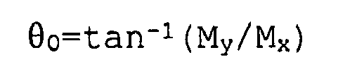
azimuth calculation section 17 calculates azimuth θ based on the signs of the x, y, z-axis components Mx, My, Mz of earth magnetism M and Formula θ=tan-1(My/Mx). - When offset calibration is in progress, the amplified output values Srx, Sry, Srz of the x-axis Hall element HEx, y-axis Hall element HEy and z-axis Hall element HEz are output to the offset
information calculation section 18. - When the orientation of the
portable device 201 is arbitrarily changing in a three-dimensional space, the offsetinformation calculation section 18 acquires the amplified output values Srx, Sry, Srz of the x-axis Hall element HEx, y-axis Hall element HEy and z-axis Hall element HEz a predetermined number of times or more and corrects sensitivity based on the sensitivity correction information stored in the sensitivity correctioninformation storage section 19b. - Here, the amplified output value Sx of the x-axis Hall element HEx, amplified output value Sy of the y-axis Hall element HEy and amplified output value Sz of the z-axis Hall element HEz after the sensitivity correction can be expressed by Formulas (8), (9) and (10) below:


where a0/ax is a sensitivity correction coefficient of the x-axis Hall element HEx, a0/ay is a sensitivity correction coefficient of the y-axis Hall element HEy, a0/az is a sensitivity correction coefficient of the z-axis Hall element HEz and a0 is sensitivity after the sensitivity corrections of the x-axis Hall element HEx, y-axis Hall element HEy and z-axis Hall element HEz. - Furthermore, Cx is an offset after the sensitivity correction of the x-axis Hall element HEx, Cy is an offset after the sensitivity correction of the y-axis Hall element HEy and Cz is an offset after the sensitivity correction of the z-axis Hall element HEz, and


- When the amplified output values Sx, Sy, Sz are arranged on an xyz coordinate system as the x, y, z components respectively, the offset
information calculation section 18 estimates the coordinates of a reference point whose distances from the respective points become as equal as possible. - The offset
information storage section 19a stores the x component of the coordinates of this reference point as a current offset Cx of the x-axis Hall element HEx, the y component of the coordinates of this reference point as a current offset Cy of the y-axis Hall element HEy and the z component of the coordinates of this reference point as a current offset Cz of the z-axis Hall element HEz. - Since sensitivity of the x-axis Hall element HEx, y-axis Hall element HEy and z-axis Hall element HEz hardly changes when the
portable device 201 is in use, the sensitivity correction information on the x-axis Hall element HEx, y-axis Hall element HEy and z-axis Hall element HEz may be stored only once when theportable device 201 is manufactured. -
Figure 3 illustrates the concept of the azimuth measuring method according to an embodiment of the present invention. - In
Figure 3 , the orientation of theportable device 201 is changed arbitrarily in a three-dimensional space and the amplified output value Sx of the x-axis Hall element HEx, amplified output value Sy of the y-axis Hall element HEy and the amplified output value Sz of the z-axis Hall element HEz are acquired repeatedly in the meantime. Then, as shown inFigure 3 , in the xyz space in which Sx, Sy, Sz correspond to the x, y, z-axis direction components, the repeatedly acquired Sx, Sy, Sz data are arranged as P1(S1x, S1y, S1z), P2(S2x, S2y, S2z), P3(S3x, S3y, S3z),... - Here, when Formulas (8), (9), (10) aremodifiedas follows:


- On the other hand, the relationship between Mx, My, Mz and earth magnetism M is:

and earth magnetism M can be considered constant unless the location of theportable device 201 is changed drastically. - Thus, if

is assumed, the following formula holds:
- That is, in the xyz space, P1(S1x, S1y, S1z), P2(S2x, S2y, S2z), P3(S3x, S3y, S3z), ··· are all located at a constant distance r from a reference point C1 whose x, y, z-axis coordinate values consist of offsets Cx, Cy, Cz of the HEx, HEy, HEz.
- Therefore, by estimating the reference point C1 from P1(S1x, S1y, S1z), P2(S2x, S2y, S2z), P3(S3x, S3y, S3z), ···, it is possible to obtain the offsets Cx, Cy, Cz of the HEx, HEy, HEz from the x, y, z-axis coordinate values of C1.
- There are various types of calculation methods to estimate C1 and C1 can be estimated by acquiring data at least four times. However, since the Sx, Sy, Sz data actually acquired are measured data of extremely feeble earth magnetism on the order of 0.01 mT and overlap with considerable noise, and therefore it is preferable to calculate C1 with the number of data pieces to be acquired set to 5 or 10 or more if possible using a statistical technique. Therefore, it is possible to estimate C1 accurately using the calculation method which will be described later using a statistical technique with an increase in the calculation time suppressed.
- In the xyz space whose x, y, z-axis direction components consist of Sx, Sy, Sz respectively, the distance di from the Sx, Sy, Sz data P1(S1x, S1y, S1z) which has been acquired at the ith time to C1 is as follows:

- By comparing Formula (17) with Formula (16) above, if the acquired Sx, Sy, Sz data don't overlap with noise and C1 has been estimated ideally, di must be equal to r. However, both are not always equal, and therefore the difference between the square of di and the square of r is defined as a C1 estimation error εi at Pi (Six, Siy, Siz) as shown in the following formula:

- Further, the square sum total of εi is defined as S expressed by the following formula.

- Obtaining such Cx, Cy, Cz that minimize this square sum total S is appropriate as the estimation method.
- When S becomes a minimum, the derivatives of S with respect to Cx, Cy, Cz and r are all considered to be 0. The respective derivatives become as follows:


- When all these derivatives become 0, the following formulas are obtained.


where N: number of data pieces acquired. - When Formula (27) above is solved with respect to r2, the formula becomes as follows:

- The following formulas are obtained by substituting Formula (28) into Formulas (24), (25) and (26) and rearranging them:



where


- Formulas (29), (30) and (31) are expressed in matrix forms as follows:

- Formula (35) above are simultaneous linear equations with respect to Cx, Cy, Cz and the solutions can be calculated using well known solutions to simultaneous linear equations such as LU decomposition. Therefore, it is possible to calculate Cx, Cy, Cz when S becomes aminimumwhile suppressing an increase in the calculation time.
- The following equations are also derived from Formula (35) above, and therefore a formula which is convenient for calculation of the solution can be selected.


- Furthermore, if the number of data pieces acquired is increased and an estimation calculation of the reference point C1 is performed using the above described calculation method, the Sx, Sy, Sz data P1 (S1x, S1y, S1z), P2(S2x, S2y, S2z), P3(S3x, S3y, S3z), ··· repeatedly acquired in
Figure 3 need not always be distributed in all directions when viewed from C1 and may also be limited to within a range of, for example, about 2π π in terms of a solid angle. That is, the directions toward P1(S1x, S1y, S1z), P2(S2x, S2y, S2z), P3(S3x, S3y, S3z), ··· viewed from C1 correspond to the orientations of theportable device 201 when the respective pieces of data are acquired, and therefore it is not necessary to orient theportable device 201 in all directions uniformly when an offset value is calibrated, and the orientations of theportable device 201 may be limited to within a range of, for example, about 2π to π in terms of a solid angle. -
Figure 4 is a flow chart showing an azimuth measuring method according to an embodiment of the present invention. - In
Figure 4 , the offsetinformation calculation section 18 provides a data buffer for storing the amplified output value Srx of the x-axis Hall element HEx, amplified output value Sry of the y-axis Hall element HEy and amplified output value Srz of the z-axis Hall element HEz, 10 values each (step S11). - Then, the offset
information calculation section 18 acquires the amplified output values Srx, Sry, Srz of the x-axis Hall element HEx, y-axis Hall element HEy and z-axis Hall element HEz, 10 values each (step S12, S13), multiplies the amplified output values Srx, Sry, Srz of the x-axis Hall element HEx, y-axis Hall element HEy and z-axis Hall element HEz by sensitivity correction coefficients respectively based on the sensitivity correction information stored in the sensitivity correctioninformation storage section 19b to obtain amplified output values Sx, Sy, Sz after sensitivity corrections of the x-axis Hall element HEx, y-axis Hall element HEy and z-axis Hall element HEz. - After acquiring the amplified output values Sx, Sy, Sz after sensitivity corrections of the x-axis Hall element HEx, y-axis Hall element HEy and z-axis Hall element HEz, 10 values each, the offset
information calculation section 18 deletes the oldest data from the data buffer, shifts the remaining data and adds the amplified output values Sx, Sy, Sz acquired this time (step S14). - Then, the offset
information calculation section 18 decides whether the difference between a maximum value and minimum value of the respective past 10 amplified output values Sx, Sy, Sz after sensitivity corrections of the x-axis Hall element HEx, y-axis Hall element HEy and z-axis Hall element HEz is greater than a predetermined value, for example, about 1/3 of a0M or not (step S15). - When the difference between a maximum value and minimum value obtained in step S15 is equal to or smaller than the predetermined value, the offset
information calculation section 18 discards the amplified output values Sx, Sy, Sz acquired this time, goes back to step S12 and newly acquires amplified output values Srx, Sry, Srz of the x-axis Hall element HEx, y-axis Hall element HEy and z-axis Hall element HEz. - On the other hand, when the difference between a maximum value and minimum value obtained in step S15 is greater than the predetermined value, the offset
information calculation section 18 estimates the coordinates (Cx, Cy, Cz) of such a reference point C1 whose distances from points P1(S1x, S1y, S1z), P2(S2x, S2y, S2z), P3(S3x, S3y, S3z) , ··· in which the 10 amplified output values Sx, Sy, Sz correspond to xyz components respectively become as equal as possible (step S16). - Next, the offset
information calculation section 18 decides whether the difference between the coordinates (Cx, Cy, Cz) of the reference point C1 estimated this time and the coordinates (Cx, Cy, Cz) of the reference point C1 estimated last time is smaller than a predetermined value, for example, about a0M or not (step S17), discards the coordinates (Cx, Cy, Cz) of the reference point C1 estimated this time if it is equal to or greater than the predetermined value, goes back to step S12 and newly acquires amplified output values Srx, Sry, Srz of the x-axis Hall element HEx, y-axis Hall element HEy and z-axis Hall element HEz. - On the other hand, when the difference between the coordinates (Cx, Cy, Cz) of the reference point C1 estimated this time and the coordinates (Cx, Cy, Cz) of the reference point C1 estimated last time is smaller than the predetermined value, the offset
information calculation section 18 causes the offsetinformation storage section 19a to store the x, y, z components of the coordinates (Cx, Cy, Cz) of the reference point C1 estimated this time as the offset Cx of the x-axis Hall element HEx, offset Cy of the y-axis Hall element HEy and offset Cz of the z-axis Hall element HEz (step S18). - The above described embodiment assumes that the azimuth measuring device is incorporated in the portable device, but it is also possible to accommodate the azimuth measuring device in a case which can be inserted into or detached from a portable device such as a PDA (Personal Digital Assistant) or notebook personal computer and use this azimuth measuring device mounted in the portable device.
- For example, it is possible to provide the azimuth measuring device, its data processing IC and interface IC, etc., in a PCMCIA card inserted in a PC card slot provided as standard for a notebook personal computer and incorporate the above-described calibration function as a driver.
- The PC card slot has a standard for mechanical and electrical characteristics but has no magnetic characteristic such as leakage flux density inside the slot, and therefore the azimuth measuring device provided inside a general-purpose PCMCIA card cannot predict leakage flux density generated in the notebook personal computer beforehand.
- Here, by incorporating the calibration function of the azimuth measuring device in the PCMCIA card, it is possible to accurately correct an offset of the azimuth measuring device even when the leakage magnetic field of the PC card slot varies from one portable device to another and freely mount and use the azimuth measuring device without being limited to a specific portable device.
- In the PCMCIA card, it is also possible to mount a tilt sensor, signal processing IC of a GPS (Global Positioning System) and antenna together with the azimuth measuring device and the card format is not limited to the PCMCIA card and may also be made adaptable to a CF card slot.
- Furthermore, the above described embodiment has described the case where Hall elements are used as magnetic sensors as an example, but the magnetic sensors are not limited to Hall elements and flux gate sensors, etc., may also be used.
- In the above described embodiment, the offset information calculation section 18 is constructed so as to estimate the coordinates of a reference point in such a way that when amplified output values Sx, Sy, Sz are arranged on an xyz coordinate system as points representing x, y, z components respectively, distances of the reference point from the respective points become as equal as possible, but the present invention is not limited to this and the offset information calculation section 18 may also be adapted so as to estimate the coordinates of a reference point in such a way that in the case where the rates of variation of the amplified output values Sx, Sy, Sz are all equal to or greater than a predetermined value, for example, about 1/3 of a0M, the amplified output values Sx, Sy, Sz are arranged on an xyz coordinate system as points representing x, y, z components, the distances of the reference point from the respective points become as equal as possible, and when one of the amplified output values Sx, Sy, Sz has a minimum rate of variation and when the rate of variation of that amplified output value is equal to or smaller than a predetermined value, the offset information calculation section 18 may also be adapted so as to estimate the coordinates of a reference point in such a way that when the amplified output values of other than that having the minimum rate of variation out of the amplified output values Sx, Sy, Sz are arranged on an xy coordinate system as points representing x, ycomponents respectively, the distances from the respective points become as equal as possible.
- As a specific method of calculating the rates of variations of amplified output value Sx, Sy, Sz, a calculation of standard deviation, calculation of a difference between a maximum value and minimum value, etc., may be used.
- Thus, even when the azimuth measuring device is moved or rotated only on a plane perpendicular to any one of three axes of the three-axis
magnetic sensor 11, it is possible to estimate the coordinates of a reference point relatively accurately. - Furthermore, the above described embodiment is constructed in such a way that it is decided in steps S7, S17 whether a difference between the coordinates (Cx, Cy, Cz) of the reference point C1 estimated this time and the coordinates (Cx, Cy, Cz) of the reference point C1 estimated last time is smaller than a predetermined value or not, but the present invention is not limited to this and the present invention may also be adapted so as to compare the coordinates (Cx, Cy, Cz) of the reference point C1 estimated this time with the coordinates (Cx, Cy, Cz) of a plurality of reference points C1 estimated last time and before last time. More specifically, variations of a predetermined number of reference points C1 estimated latest (including reference point C1 estimated this time) are calculated and the calculated degrees of variations are decided. There may be various methods for calculating variations such as calculating a difference between a maximum value and minimum value of those reference points C1, calculating a standard deviation of those reference points C1, calculating an average of reference points C1 estimated until last time and calculating a difference between the reference points C1 estimated this time and the average, etc. Thus, using a plurality of past estimated values for the coordinates of a reference point C1 can further improve the accuracy.
- Furthermore, the above described embodiment has not particularly referred to displaying the acceptability of offset information, but the present invention is not limited to this and may also be adapted so as to display the acceptability of offset information on the
display section 202. More specifically, the degree of acceptability of offset information is classified into a plurality of categories such as excellent, good and fair. Then, focused on a predetermined number of reference points C1 estimated latest (including reference point C1 estimated this time), variations of those reference points C1 are calculated, the reference point C1 estimated this time is classified into any one of categories according to the calculated degree of variations, acceptability information indicating the acceptability corresponding to the category is created and the degree of acceptability of the offset information is displayed on thedisplay section 202 based on the acceptability information created. - Here, the aforementioned method can be used to use a plurality of past estimated values of the coordinates of reference points C1.
- This allows the user to recognize the acceptability of offset information with reference to the degree of acceptability displayed.
- Furthermore, in the above described embodiment, it is possible to calculate the distances from Sx, Sy, Sz data P1 (S1x, S1y, S1z), P2(S2x, S2y, S2z), P3(S3x, S3y, S3z), ... repeatedly acquired in
Figure 3 to the estimated reference point C1, decide whether the calculated distance is outside a predetermined range, for example, smaller than 1/2 of a0M or greater than 1.5 times a0M or not, and discard the output data if the calculated distance is outside the predetermined range. The distance can also be calculated from Formula (28) above using the following formula:
- Thus, when a static external environment magnetic field exists or earth magnetism is shielded, it is possible to prevent azimuth from being measured despite the fact that earth magnetism has not been detected correctly.
- Furthermore, the above described embodiment can also be adapted so as to display reliability of the azimuth measurement result on the
display section 202. More specifically, the reliability of the azimuth measurement result is divided into a plurality of categories such as excellent, good and fair. Then, the distances from points P1 (S1x, S1y, S1z), P2(S2x, S2y, S2z), P3(S3x, S3y, S3z) , ··· to the coordinates (Cx, Cy, Cz) of the reference point C1 are calculated, the calculated distances are compared with a plurality of thresholds, classified into anyone of categories, reliability information showing the degree of reliability corresponding to the category is created and the degree of reliability of the azimuth measurement result is displayed on thedisplay section 202 based on the reliability information created. - This allows the user to recognize the reliability of the azimuth measurement result with reference to the degree of reliability displayed.
- The above described embodiment has described the case of the azimuth measuring device having 3-axis earth magnetism detection means, but the present invention is not limited to this and the present invention is also applicable to an azimuth measuring device having 2-axis earth magnetism detection means as shown in
Figure 5 . - In this case, a block diagram showing a schematic structure of the azimuth measuring device, a figure illustrating the concept of the azimuth measuring method and a flow chart of offset calibration are as shown in
Figure 6 to 8 . - Furthermore, in the case of the azimuth measuring device having 3-axis earthmagnetism detectionmeans, the orientation of the
portable device 201 is arbitrarily changed in a three-dimensional space and the amplified output value Sx of the x-axis Hall element HEx, amplified output value Sy of the y-axis Hall element HEy and amplified output value Sz of the z-axis Hall element HEz are acquired repeatedly in the meantime, but in the case of the azimuth measuring device having 2-axis earth magnetism detection means, the orientation of theportable device 101 is changed while keeping the earth magnetism detection directions of two axes on a predetermined plane and the amplified output value Sx of the x-axis Hall element HEx and amplified output value Sy of the y-axis Hall element HEy are acquired repeatedly in the meantime. By replacing Formulas (14) to (37) above by Formulas (39) to (58) shown below, the present invention can be applied likewise.








- Furthermore, when a reference point C2 is estimated by solving the simultaneous linear equations shown in Formulas (56), (57) or (58), increasing the number of data pieces acquired eliminates the necessity for uniformly orienting the
portable device 101 which calibrates offset values in all directions and the orientation of theportable device 101 may be limited within a range of about 180° to 90°. By replacing Formula (38) by Formula (59) below, the present invention can be applied likewise.
- In acquiring the Sx, Sy, Sz data, the above described embodiment repeats data acquisition unconditionally until the number of data pieces acquired reaches a predetermined value. However, it is also possible to calculate a difference between the Sx, Sy, Sz data acquired immediately before every time the Sx, Sy, Sz data is acquired and discard the acquired Sx, Sy, Sz data when the difference is smaller than the predetermined value.
- Thus, even when a state in which the orientation of the portable device hardly changes during calibration continues, it is possible to prevent wrong offset values from being calculated causing inappropriate offset corrections to be carried out.
-
Figure 9 shows an example of the Sx, Sy, Sz data acquired when the orientation of the portable device is changing appropriately and all data is changing with time. On the other hand,Figure 10 shows an example of the Sx, Sy, Sz data acquired when the orientation of the portable device hardly changes and all data remains substantially constant. - In the case of the Sx, Sy, Sz data shown in
Figure 10 , the difference between the maximum value and minimum value of the Sx, Sy, Sz data is decided to be equal to or below a predetermined value in step S15 in the offset calibration flow chart shown inFigure 4 , and therefore the process does not move to the step of estimating a reference point. - However, when the orientation of the portable device changes only for a short time while the Sx, Sy, Sz data is being acquired, the Sx, Sy, Sz data becomes as shown in
Figure 11 and parts whose values change appear. In this case, in step S15, the difference between the maximum value and minimum value of the Sx, Sy, Sz data may be decided to be greater than a predetermined value and the process may move to the step of estimating a reference point. This causes a considerably large error to occur in estimating the reference point with the result that wrong offset values are calculated. - Therefore, by calculating difference from the Sx, Sy, Sz data acquired immediately before every time the Sx, Sy, Sz data is acquired and discarding the Sx, Sy, Sz data when the difference is smaller than a predetermined value, it is possible to prevent reference points from being estimated with inappropriate Sx, Sy, Sz data because the acquired Sx, Sy, Sz data is discarded as long as the orientation of the portable device hardly changes.
- There may be various specific methods of calculating differences of Sx, Sy, Sz data and deciding whether or not to discard the data, for example, calculating a difference for each piece of the Sx, Sy, Sz data and discarding the Sx, Sy, Sz data if all the differences do not exceed a predetermined value or calculating the sum of squares of respective differences of the Sx, Sy, Sz data and discarding the Sx, Sy, Sz data when the result does not exceed the predetermined value.
- As described above, according to the azimuth measuring device or the azimuth measuring method, it is possible to calculate offset information with respect to the output of each axis of the earth magnetism detection means by only arbitrarily changing the orientation of the portable device, simplify the offset calibration work and reduce load on the user when carrying out offset calibration.
Claims (18)
- An azimuth measuring device comprising:earth magnetism detection means (1,11) with 2 or 3 axes for detecting earth magnetism (M);output data acquisition means adapted to acquire 2-axis output data Pi (Six, Siy) when an orientation of said earth magnetism detection means (1, 11) changes while keeping detection directions of said two axes on a predetermined plane or 3-axis output data Pi (Six, Siy, Siz) when the orientation of said earth magnetism detection means (1,11) changes in a three-dimensional space repeatedly a predetermined number of times or more;reference point estimation means (8, 18) adaptedto define a reference point C(Cx, Cy) on a two-dimensional coordinate system wherein said 2-axis output data Pi (Six, Siy) are all located at an average distance r from the reference point C(Cx, Cy) or a reference point C(Cx, Cy, Cz) on a three-dimensional coordinate system wherein said 3-axis output data Pi (Six, Siy, Siz) are all located at the average distance r from the reference point C(Cx, Cy, Cz), andto estimate the coordinates of the reference point C using a statistical technique so that a square sum total S of a difference between a square of a distance di and a square of the average distance r2 is minimized, the distance di being a distance from the 2-axis output data Pi (Six, Siy) or the 3-axis output data Pi (Six, Siy, Siz) to the reference point C, wherein


or,

respectively; andoffset information calculation means (8, 18) adapted to calculate offset information with respect to the output data of said earth magnetism detection means (1, 11) based on said coordinates of the reference point C,wherein the offset information calculation means (8, 18) comprises variation calculation means adapted to calculate a variation of a predetermined number of the latest reference points calculated by said reference point estimation means (8, 18),wherein said offset information calculation means (8, 18) is adapted to discard the reference point calculated by said reference point estimation means (8, 18) based on the calculation result of said variation calculation means, andwherein said output data acquisition means is adapted to newly acquire the output data of said earth magnetism detection means (1,11), when said offset information calculation means (8,18) discards the reference point C. - The azimuth measuring device according to claim 1, wherein said reference point estimation means (8, 18) is adapted to calculate a simultaneous linear equation with the coordinates of the reference point C being unknowns to estimate said coordinates of the reference point C and to calculate coefficients and constant terms of the simultaneous linear equation from the 2-axis output data or the 3-axis output data.
- The azimuth measuring device according to claim 1, characterized in that said earth magnetism detection means (1, 11) is 3-axis earth magnetism detection means, and
when a degree of the variation of the output data is a predetermined value or below with respect to the output data of the axis whose degree of variation is a minimum out of the 3-axis output data, said reference point estimation means defines a reference point on a two-dimensional coordinate system whose coordinate values correspond to the 2-axis output data for the 2-axis output data which is generated by excluding the output data of the axis whose degree of variation is a minimum from said 3-axis output data and estimates said coordinates or reference point from said 2-axis output data. - The azimuth measuring device according to claim 1, characterized in that said reference point estimation means (8, 18) comprises:difference calculation means adapted to calculate a difference between a maximum value and a minimum value of output data in the output data of each axis from said 2-axis or 3-axis output data; anddifference decision means adapted to decide whether or not the difference calculated by said difference calculation means is equal to or greater than a predetermined value,wherein said reference point estimation means (8, 18) uses said 2-axis or 3-axis output data for estimating said reference point C only when the difference calculated by said difference calculation means is equal to or greater than the predetermined value.
- The azimuth measuring device according to claim 1, characterized in that said variation calculation means calculates the difference between the two latest reference points calculated by said reference point estimation means.
- The azimuth measuring device according to claim 1, further comprising:variation calculation means adapted to calculate a variation of a predetermined number of the latest reference points calculated by said reference point estimation means (8, 18); andacceptability information creation means adapted to create acceptability information regarding the acceptability of said offset information based on the calculation result of said variation calculation means.
- The azimuth measuring device according to claim 6, characterized in that said acceptability information creation means divides the degree of acceptability of said offset information into a plurality of categories, classifies the offset information into any one of said categories according to the degree of variation calculated by said variation calculation means and displays the degree of acceptability corresponding to the category.
- The azimuth measuring device according to claim 1, characterized in that said offset information calculation means (8, 18) comprises:distance calculation means adapted to calculate the distance from said output data to said reference point C; anddistance decision means adapted to decide whether the distance calculated by said distance calculation means is outside a predetermined ranger or not,wherein said offset information calculation means is adapted to discard the output data when the distance calculated by said distance calculation means is outside the predetermined range.
- The azimuth measuring device according to claim 1, further comprising:distance calculation means adapted to calculate the distance from said output data to said reference point; andreliability information creation means adapted to create reliability information regarding the reliability of the azimuth measurement result based on the distance calculated by said distance calculation means.
- The azimuth measuring device according to claim 9, characterized in that said reliability information creation means divides the degree of reliability of said azimuth measurement result into a plurality of categories, compares the distance calculated by said distance calculation means with a plurality of thresholds, classifies the distance into any one of said categories and displays the degree of reliability corresponding to the category.
- The azimuth measuring device according to claim 1, characterized in that said output data acquisition means comprises:difference calculation means adapted to calculate a difference between the output data output from said earth magnetism detection means and a predetermined number of pieces of immediately preceding output data acquired by said output data acquisition means or the output data output immediately before from said earth magnetism detection means; anddifference decision means adapted to decide whether or not the difference calculated by said difference calculation means is smaller than a predetermined value,wherein said output data acquisition means does not acquire but discards the output data output from said earth magnetism detection means when the difference calculated by said difference calculation means is smaller than the predetermined value.
- An azimuth measuring method comprising steps of:changing detection directions of two axes for measurement of earth magnetism while keeping the detection directions of two axes on a predetermined plane or changing the detection directions of three axes in a three-dimensional space;acquiring the 2-axis output data Pi(Six, Siy) or 3-axis output data Pi(Six, Siy, Siz) for measurement of earth magnetism when said detection directions change;deciding whether said output data is acquired a predetermined number of times or more or not;defining a reference point C (Cx, Cy) on a two-dimensional coordinate system wherein said 2-axis output data Pi(Six, Siy) are all located at an average distance r from the reference point C (Cx, Cy) or a reference point C(Cx, Cy, Cz) on a three-dimensional coordinate system wherein said 3-axis output data Pi(Six, Siy, Siz) are all located at an average distance r from the reference point C(Cx, Cy, Cz), andestimating the coordinates of the reference point C using a statistical technique so that a square sum total S of a difference between a square of a distance di and a square of an average distance r2 is minimized, the distance di being a distance from the 2-axis output data Pi (Six, Siy) or the 3-axis output data Pi (Six, Siy, Siz) to the reference point C, wherein


or,

respectively; andcalculating offset information with respect to said 2-axis output data Pi(Six, Siy) or said 3-axis output data Pi(Six, Siy, Siz) based on said estimated coordinates of the reference point C,wherein the step of calculating the offset information with respect to said 2-axis output data Pi(Six, Siy) or 3-axis output data Pi(Six, Siy, Siz) comprises:calculating a variation of a predetermined number of the latest reference points calculated in the step of estimating the coordinates of the reference point C;discarding the reference point C calculated in the step of estimating the coordinates of the reference point C based on the calculation result of said variation; andnewly acquiring output data for measurement of earth magnetism, when the reference point C is discarded. - The azimuth measuring method according to claim 12, characterized in that said step of estimating the coordinates of the reference point C comprises:calculating coefficients and constant terms of simultaneous linear equations whose unknowns are said coordinates of the reference point C from said 2-axis or 3-axis output data; andcalculating solutions to said simultaneous linear equations including said coefficients and constant terms and estimating said coordinates of reference point.
- The azimuth measuring method according to claim 12, characterized in that said step of changing said detection direction is intended to change detection directions of three axes in a three-dimensional space, and said step of estimating the coordinates of reference point comprises steps of:calculating the degree of variation of output data of the output data of each axis of said 3-axis output data and obtaining the axis corresponding to the minimum degree of variation and a minimum value of said degree of variation,deciding whether or not said minimum value of the degree of variation is equal to or lower than a predetermined value; anddefining, when said minimum value of the degree of variation is equal to or lower than the predetermined value, a reference point on a two-dimensional coordinate system whose coordinate values correspond to the 2-axis output data for the 2-axis output data wherein the output data of the axis whose degree of variation becomes a minimum is excluded from said 3-axis output data and estimating said coordinates of reference point from said 2-axis output data.
- The azimuth measuring method according to claim 12, characterized in that said step of estimating the coordinates of reference point comprises steps of:calculating the difference between a maximum value and a minimum value of output data of the output data of each axis of said output data;deciding whether or not the difference between said maximum value and minimum value is equal to or greater than a predetermined value; andestimating said coordinates of reference point when said difference between the maximum value and minimum value is equal to or greater than the predetermined value.
- The azimuth measuring method according to claim 12, further comprising steps of:calculating a variation of a predetermined number of said estimated latest coordinates of reference points; andcreating acceptability information regarding the acceptability of the offset values calculated in said step of calculating said offset values based on the calculation result of said variation.
- The azimuth measuring method according to claim 12, characterized in that the step of calculating offset values with respect to said 2-axis or 3-axis output data comprises steps of:calculating the distance from said output data to said reference point;deciding whether the distance from said output data to said reference point is outside a predetermined range or not; anddiscarding the output data when the distance from said output data to said reference point is outside the predetermined range.
- The azimuth measuring method according to claim 12, further comprising steps of:calculating the distance from said output data to said reference point; andcreating reliability information regarding the reliability of the azimuth measurement result based on said distance calculation result.
Applications Claiming Priority (5)
| Application Number | Priority Date | Filing Date | Title |
|---|---|---|---|
| JP2002192546 | 2002-07-01 | ||
| JP2002192546 | 2002-07-01 | ||
| JP2003035010 | 2003-02-13 | ||
| JP2003035010 | 2003-02-13 | ||
| PCT/JP2003/008293 WO2004003476A1 (en) | 2002-07-01 | 2003-06-30 | Azimuth measuring device and azimuth measuring method |
Publications (3)
| Publication Number | Publication Date |
|---|---|
| EP1519148A1 EP1519148A1 (en) | 2005-03-30 |
| EP1519148A4 EP1519148A4 (en) | 2007-07-25 |
| EP1519148B1 true EP1519148B1 (en) | 2014-08-06 |
Family
ID=30002335
Family Applications (1)
| Application Number | Title | Priority Date | Filing Date |
|---|---|---|---|
| EP03738595.2A Expired - Lifetime EP1519148B1 (en) | 2002-07-01 | 2003-06-30 | Azimuth measuring device and azimuth measuring method |
Country Status (7)
| Country | Link |
|---|---|
| US (1) | US7177779B2 (en) |
| EP (1) | EP1519148B1 (en) |
| JP (1) | JP4391416B2 (en) |
| KR (4) | KR100939158B1 (en) |
| CN (1) | CN100535593C (en) |
| AU (1) | AU2003246158A1 (en) |
| WO (1) | WO2004003476A1 (en) |
Families Citing this family (70)
| Publication number | Priority date | Publication date | Assignee | Title |
|---|---|---|---|---|
| ATE504804T1 (en) | 2003-07-03 | 2011-04-15 | Asahi Kasei Emd Corp | AZIMUTH MEASURING DEVICE AND AZIMUTH MEASURING METHOD |
| JP4489023B2 (en) * | 2003-12-22 | 2010-06-23 | 旭化成エレクトロニクス株式会社 | Azimuth measuring device |
| JP4559888B2 (en) * | 2004-03-19 | 2010-10-13 | 旭化成エレクトロニクス株式会社 | Geomagnetism measuring apparatus and geomagnetism measuring method |
| EP1605232A3 (en) | 2004-06-11 | 2010-12-29 | Yamaha Corporation | Method and apparatus for measuring magnetic offset of geomagnetic sensor and portable electronic apparatus |
| JP4639672B2 (en) * | 2004-07-12 | 2011-02-23 | ヤマハ株式会社 | Geomagnetic sensor correction method |
| US8065083B2 (en) * | 2004-07-23 | 2011-11-22 | Yamaha Corporation | Azimuth processing device, azimuth processing method, azimuth processing program, direction finding device, tilt offset correcting method, azimuth measuring method, compass sensor unit, and portable electronic device |
| WO2006009247A1 (en) * | 2004-07-23 | 2006-01-26 | Yamaha Corporation | Direction processor, direction processing method, direction processing program, direction measuring instrument, inclination offset correcting method, direction measuring method, direction sensor unit and portable electronic device |
| WO2006011276A1 (en) * | 2004-07-23 | 2006-02-02 | Yamaha Corporation | Direction processing device, direction processing method, direction processing program, direction measuring device, and geographic information display |
| KR100856192B1 (en) * | 2004-07-29 | 2008-09-03 | 야마하 가부시키가이샤 | Azimuth data calculation method, azimuth sensor unit and portable electronic device |
| WO2006011238A1 (en) * | 2004-07-29 | 2006-02-02 | Yamaha Corporation | Azimuth data arithmetic method, azimuth sensor unit, and mobile electronic device |
| KR100847382B1 (en) * | 2004-08-10 | 2008-07-18 | 야마하 가부시키가이샤 | Azimuth data producing method, azimuth sensor unit and portable electronic device |
| US7653507B2 (en) * | 2004-08-12 | 2010-01-26 | Asahi Kasei Emd Corporation | Acceleration measuring device |
| CN1871496B (en) * | 2004-09-29 | 2010-04-28 | 阿莫善斯有限公司 | Magnetic sensor control method, control device, and mobile terminal device |
| JP4398981B2 (en) * | 2004-11-11 | 2010-01-13 | ソフトバンクモバイル株式会社 | Measuring method and movement information device |
| JP4879495B2 (en) * | 2005-02-15 | 2012-02-22 | 日本電信電話株式会社 | Accelerometer |
| JP2006234581A (en) * | 2005-02-24 | 2006-09-07 | Aichi Micro Intelligent Corp | Electronic compass and azimuth measuring method |
| EP1775550B1 (en) * | 2005-10-11 | 2013-12-11 | Yamaha Corporation | Magnetic sensor control device |
| JP4830441B2 (en) * | 2005-10-11 | 2011-12-07 | ヤマハ株式会社 | Magnetic sensor control device, method and program |
| JP4899525B2 (en) * | 2006-02-21 | 2012-03-21 | ヤマハ株式会社 | Magnetic sensor control device, magnetic measurement device, offset setting method and program |
| JP2007327934A (en) * | 2006-05-10 | 2007-12-20 | Yamaha Corp | Magnetic data processing device, method, and program |
| KR100890307B1 (en) | 2006-03-07 | 2009-03-26 | 야마하 가부시키가이샤 | Magnetic data processing device |
| JP4761142B2 (en) * | 2006-03-31 | 2011-08-31 | ヤマハ株式会社 | Magnetic data processing method, apparatus and program |
| WO2007129653A1 (en) * | 2006-05-09 | 2007-11-15 | Alps Electric Co., Ltd. | Calibration program and electronic compass |
| KR100799877B1 (en) * | 2006-09-20 | 2008-01-30 | 삼성전기주식회사 | Offset correction device and method of geomagnetic sensor |
| US20100277163A1 (en) | 2007-02-09 | 2010-11-04 | Asahi Kasei Emd Corporation | Spatial Information Detecting System, its Detecting Method, and Spatial Information Detecting Device |
| JP4935427B2 (en) * | 2007-03-01 | 2012-05-23 | ヤマハ株式会社 | Magnetic data processing apparatus, method and program, and magnetic processing system. |
| FI119663B (en) * | 2007-04-24 | 2009-01-30 | Tracker Oy | Guiding positioning method, pointing device and computer program product |
| JP4787359B2 (en) * | 2007-05-24 | 2011-10-05 | 旭化成エレクトロニクス株式会社 | Physical quantity measuring apparatus and physical quantity measuring method |
| EP2028504B1 (en) * | 2007-08-23 | 2016-04-13 | STMicroelectronics Srl | Method and device for calibrating a magnetic sensor |
| EP2215494A1 (en) * | 2007-11-30 | 2010-08-11 | Nokia Corporation | Controlling operation of a positioning module |
| JP5168629B2 (en) * | 2008-02-08 | 2013-03-21 | 旭化成エレクトロニクス株式会社 | Azimuth angle measuring apparatus and azimuth angle measuring method |
| EP2093829A1 (en) * | 2008-02-21 | 2009-08-26 | Nokia Siemens Networks Oy | Antenna with levelling device and associated method |
| JP5621181B2 (en) * | 2008-03-28 | 2014-11-05 | ヤマハ株式会社 | Magnetic data processing apparatus, magnetic data processing method, and magnetic data processing program |
| WO2010004873A1 (en) * | 2008-07-08 | 2010-01-14 | アルプス電気株式会社 | Azimuth calculation device and azimuth calculation method |
| WO2010040007A2 (en) * | 2008-10-01 | 2010-04-08 | A-Tech Corporation | Method and apparatus for precision azimuth measurement |
| KR101267163B1 (en) | 2008-11-20 | 2013-05-24 | 아사히 가세이 일렉트로닉스 가부시끼가이샤 | Physical quantity measurement device and physical quantity measurement method |
| JP2010223829A (en) * | 2009-03-24 | 2010-10-07 | Fujitsu Ltd | Mobile device and program |
| KR20120008494A (en) * | 2009-05-14 | 2012-01-30 | 닛본 덴끼 가부시끼가이샤 | How to calibrate geomagnetic sensors on mobile devices, mobile devices and programs |
| JP5453969B2 (en) * | 2009-07-10 | 2014-03-26 | ヤマハ株式会社 | Magnetic data processing apparatus, magnetic data processing method, and magnetic data processing program |
| US8954271B2 (en) * | 2009-11-06 | 2015-02-10 | The University Of Maryland, College Park | Method and system for determining relative displacement and heading for navigation |
| JP4947669B2 (en) * | 2009-12-01 | 2012-06-06 | 旭化成エレクトロニクス株式会社 | Azimuth angle measuring method and azimuth angle measuring apparatus |
| US8965076B2 (en) | 2010-01-13 | 2015-02-24 | Illumina, Inc. | Data processing system and methods |
| JP2011203243A (en) * | 2010-03-02 | 2011-10-13 | Yamaha Corp | Magnetic data processing apparatus, method and program |
| JP5374422B2 (en) * | 2010-03-10 | 2013-12-25 | アルプス電気株式会社 | Magnetic field detector |
| JP5531801B2 (en) * | 2010-06-16 | 2014-06-25 | ヤマハ株式会社 | 3-axis magnetic sensor, electronic compass |
| US8843338B2 (en) | 2011-07-29 | 2014-09-23 | Nokia Corporation | Processing Data for Calibration |
| CN102322845B (en) * | 2011-09-07 | 2014-02-19 | 华为技术有限公司 | Apparatus for detecting azimuth, and method thereof |
| US9354257B2 (en) | 2011-11-04 | 2016-05-31 | General Electric Company | Systems and methods for use in measuring current through a conductor |
| FR2992735B1 (en) * | 2012-06-29 | 2015-07-03 | Movea | METHOD OF CONTINUOUS CALIBRATION OF A SENSOR |
| FI126012B (en) | 2012-12-31 | 2016-05-31 | Suunto Oy | Method and device for determining direction in a magnetic field |
| JP6191145B2 (en) * | 2013-01-31 | 2017-09-06 | ヤマハ株式会社 | Offset estimation apparatus and program |
| WO2014141631A1 (en) | 2013-03-15 | 2014-09-18 | 旭化成エレクトロニクス株式会社 | Physical volume data correction device and physical volume data correction method |
| KR102006029B1 (en) | 2013-07-24 | 2019-08-01 | 매그나칩 반도체 유한회사 | Method and Apparatus for calculation azimuth |
| JP2015040783A (en) * | 2013-08-22 | 2015-03-02 | ソニー株式会社 | Information processing apparatus, information processing method, and recording medium |
| TWI509271B (en) * | 2013-12-09 | 2015-11-21 | Voltafield Technology Corp | Magnetic sensors and electronic compass using the same |
| JP6372751B2 (en) * | 2014-09-22 | 2018-08-15 | カシオ計算機株式会社 | Electronic device, offset value acquisition method, and offset value acquisition program |
| JP6563190B2 (en) | 2014-12-11 | 2019-08-21 | ローム株式会社 | Offset calculation circuit and azimuth angle sensor using the same |
| JP6430262B2 (en) * | 2015-01-16 | 2018-11-28 | ローム株式会社 | Offset calculation apparatus and azimuth angle sensor using the same |
| KR101698682B1 (en) | 2015-08-26 | 2017-01-23 | 매그나칩 반도체 유한회사 | Method and Apparatus of correcting output value of terrestrial magnetism sensor |
| JP6787740B2 (en) | 2015-10-29 | 2020-11-18 | ローム株式会社 | Offset derivation device, offset calculation device, and azimuth sensor |
| WO2017073532A1 (en) * | 2015-10-29 | 2017-05-04 | ローム株式会社 | Offset derivation device, offset calculation device, and azimuth angle sensor |
| CN107478192A (en) * | 2016-06-08 | 2017-12-15 | 京信通信技术(广州)有限公司 | Azimuth measuring device, antenna, azimuth angle measurement system and measuring method |
| CN106323227A (en) * | 2016-08-31 | 2017-01-11 | 福州福光电子有限公司 | Method for testing azimuthal angle of base station antenna |
| JP6919164B2 (en) * | 2016-09-07 | 2021-08-18 | カシオ計算機株式会社 | Magnetic field measuring device, electronic clock, correction setting method of measured magnetic field, and program |
| JP2020134353A (en) | 2019-02-21 | 2020-08-31 | セイコーエプソン株式会社 | Electronic clock |
| KR102176767B1 (en) * | 2019-06-03 | 2020-11-09 | 주식회사 바딧 | Method, system and non-transitory computer-readable recording medium for correcting sensor data through a sepcific motion of user |
| AU2021289721B2 (en) | 2020-06-10 | 2024-03-07 | Pmotion, Inc. | Enhanced goniometer |
| CN113111312B (en) * | 2021-04-13 | 2023-09-26 | 深圳市绘王动漫科技有限公司 | Method for detecting azimuth angle and rotation angle and handwriting device |
| AU2021440674A1 (en) * | 2021-04-14 | 2023-11-16 | Ricardo POCAI | Lining for toilet seat |
| CN118897293B (en) * | 2024-09-24 | 2025-02-11 | 浙江蓝影智能技术有限公司 | Two-point distance measuring method and system based on real-time image and ranging information |
Citations (1)
| Publication number | Priority date | Publication date | Assignee | Title |
|---|---|---|---|---|
| US5151872A (en) * | 1989-10-17 | 1992-09-29 | Pioneer Electronic Corporation | Method and apparatus for correcting the output of an onboard vehicle terrestrial magnetism sensor |
Family Cites Families (18)
| Publication number | Priority date | Publication date | Assignee | Title |
|---|---|---|---|---|
| US4321678A (en) * | 1977-09-14 | 1982-03-23 | Bodenseewerk Geratetechnik Gmbh | Apparatus for the automatic determination of a vehicle position |
| US4497034A (en) * | 1981-08-05 | 1985-01-29 | Nippon Soken, Inc. | Heading detecting apparatus |
| DE3682730D1 (en) * | 1985-09-03 | 1992-01-16 | British Aerospace | CALIBRATION OF A MAGNETIC COMPASS. |
| JPS62255815A (en) | 1986-04-28 | 1987-11-07 | Nec Home Electronics Ltd | Correcting method for vehicle azimuth error |
| JPH07111348B2 (en) * | 1986-06-05 | 1995-11-29 | 日本電装株式会社 | Output correction device for azimuth detector |
| JPH0629731B2 (en) * | 1986-07-29 | 1994-04-20 | 日産自動車株式会社 | Vehicle compass |
| US5046031A (en) * | 1989-02-06 | 1991-09-03 | Magnavox Government And Industrial Electronics Company | Method and apparatus for automatic flux-gate compass calibration |
| EP0451939B1 (en) * | 1990-02-26 | 1996-01-17 | Canon Kabushiki Kaisha | Recording apparatus with a recording head having a wiring substrate |
| JPH0833301B2 (en) | 1990-04-12 | 1996-03-29 | 松下電器産業株式会社 | Magnetization correction method for geomagnetic sensor |
| JPH06221852A (en) * | 1993-01-25 | 1994-08-12 | Sato Kogyo Co Ltd | Electronic stereo clino-compass |
| US5419631A (en) * | 1994-01-12 | 1995-05-30 | Nearfield Systems Incorporated | Three-axis motion tracking interferometer for measurement and correction of positional errors between an article under test and a measurement probe |
| JPH08201059A (en) | 1995-01-20 | 1996-08-09 | Mitsubishi Electric Corp | Azimuth detector |
| JPH1026512A (en) * | 1996-07-11 | 1998-01-27 | Nikon Corp | Mobile measurement device |
| JP3282547B2 (en) * | 1997-06-27 | 2002-05-13 | 株式会社村田製作所 | External force measuring device |
| JP4004166B2 (en) | 1998-12-18 | 2007-11-07 | Necトーキン株式会社 | Geomagnetic detector |
| JP3872259B2 (en) * | 2000-07-26 | 2007-01-24 | セイコーインスツル株式会社 | Method for adjusting driving current of magnetic sensor and electronic compass |
| WO2002037827A2 (en) * | 2000-10-30 | 2002-05-10 | Naval Postgraduate School | Method and apparatus for motion tracking of an articulated rigid body |
| JP4073715B2 (en) * | 2002-06-11 | 2008-04-09 | 旭化成エレクトロニクス株式会社 | Azimuth measuring device, calibration method, and calibration program |
-
2003
- 2003-06-30 JP JP2004517329A patent/JP4391416B2/en not_active Expired - Lifetime
- 2003-06-30 CN CNB038158132A patent/CN100535593C/en not_active Expired - Lifetime
- 2003-06-30 KR KR1020097001906A patent/KR100939158B1/en not_active Expired - Fee Related
- 2003-06-30 AU AU2003246158A patent/AU2003246158A1/en not_active Abandoned
- 2003-06-30 WO PCT/JP2003/008293 patent/WO2004003476A1/en not_active Ceased
- 2003-06-30 KR KR10-2004-7019652A patent/KR20050009730A/en not_active Ceased
- 2003-06-30 EP EP03738595.2A patent/EP1519148B1/en not_active Expired - Lifetime
- 2003-06-30 US US10/519,721 patent/US7177779B2/en not_active Expired - Lifetime
- 2003-06-30 KR KR1020077022396A patent/KR20070100977A/en not_active Ceased
- 2003-06-30 KR KR1020077003751A patent/KR20070026890A/en not_active Ceased
Patent Citations (1)
| Publication number | Priority date | Publication date | Assignee | Title |
|---|---|---|---|---|
| US5151872A (en) * | 1989-10-17 | 1992-09-29 | Pioneer Electronic Corporation | Method and apparatus for correcting the output of an onboard vehicle terrestrial magnetism sensor |
Non-Patent Citations (1)
| Title |
|---|
| KÄSA: "A Circle Fitting Procedure and Its Error Anlysis", IEEE TRANSACTIONS ON INSTRUMENTATION AND MEASUREMENT, 1 March 1976 (1976-03-01), pages 8 - 14 * |
Also Published As
| Publication number | Publication date |
|---|---|
| US7177779B2 (en) | 2007-02-13 |
| JPWO2004003476A1 (en) | 2005-10-27 |
| KR100939158B1 (en) | 2010-01-28 |
| KR20090018731A (en) | 2009-02-20 |
| KR20070026890A (en) | 2007-03-08 |
| AU2003246158A1 (en) | 2004-01-19 |
| EP1519148A1 (en) | 2005-03-30 |
| US20050256673A1 (en) | 2005-11-17 |
| KR20070100977A (en) | 2007-10-15 |
| EP1519148A4 (en) | 2007-07-25 |
| KR20050009730A (en) | 2005-01-25 |
| CN1666086A (en) | 2005-09-07 |
| JP4391416B2 (en) | 2009-12-24 |
| WO2004003476A1 (en) | 2004-01-08 |
| CN100535593C (en) | 2009-09-02 |
Similar Documents
| Publication | Publication Date | Title |
|---|---|---|
| US7177779B2 (en) | Azimuth measuring device and azimuth measuring method | |
| US7376527B2 (en) | Azimuth measuring device | |
| JP4151784B2 (en) | Measuring device, azimuth measuring device, calibration program, and calibration method | |
| US8374817B2 (en) | Auto-calibration of orientation sensing systems | |
| US6836971B1 (en) | System for using a 2-axis magnetic sensor for a 3-axis compass solution | |
| US7086164B2 (en) | Method and device for measuring directional, and computer program | |
| US20020056202A1 (en) | Three-axis magnetic sensor, an omnidirectional magnetic sensor and an azimuth measureing method using the same | |
| US7278219B2 (en) | Magnetic compass | |
| JP2004525348A (en) | Monitoring the accuracy of the electronic compass | |
| JP2006113019A (en) | Triaxial type electronic compass, and azimuth detecting method using same | |
| CN103941309A (en) | Geomagnetic sensor calibration apparatus and method thereof | |
| JPWO2006035505A1 (en) | Magnetic sensor control method, control device, and portable terminal device | |
| Cho et al. | A calibration technique for a two‐axis magnetic compass in telematics devices | |
| JP4941199B2 (en) | Navigation device | |
| EP1876417A1 (en) | Inclination sensor and direction finding device using the same | |
| US20070250262A1 (en) | Device, method and medium detecting errors generated by distortion in a magnetic field | |
| JP5475873B2 (en) | Geomagnetic detector | |
| JP2006226810A (en) | Azimuth measuring instrument | |
| Li et al. | An efficient method for tri-axis magnetometer calibration | |
| CN110702102B (en) | Magnetic navigation system for navigation aircraft and navigation method thereof | |
| WO2008077595A1 (en) | A device for and a method of determining the orientation of a plane in space | |
| JP2007163389A (en) | Direction sensor |
Legal Events
| Date | Code | Title | Description |
|---|---|---|---|
| PUAI | Public reference made under article 153(3) epc to a published international application that has entered the european phase |
Free format text: ORIGINAL CODE: 0009012 |
|
| 17P | Request for examination filed |
Effective date: 20041215 |
|
| AK | Designated contracting states |
Kind code of ref document: A1 Designated state(s): AT BE BG CH CY CZ DE DK EE ES FI FR GB GR HU IE IT LI LU MC NL PT RO SE SI SK TR |
|
| AX | Request for extension of the european patent |
Extension state: AL LT LV MK |
|
| DAX | Request for extension of the european patent (deleted) | ||
| A4 | Supplementary search report drawn up and despatched |
Effective date: 20070626 |
|
| RIC1 | Information provided on ipc code assigned before grant |
Ipc: G01C 17/28 20060101AFI20070621BHEP Ipc: G01C 17/38 20060101ALI20070621BHEP |
|
| 17Q | First examination report despatched |
Effective date: 20100728 |
|
| GRAP | Despatch of communication of intention to grant a patent |
Free format text: ORIGINAL CODE: EPIDOSNIGR1 |
|
| INTG | Intention to grant announced |
Effective date: 20140416 |
|
| GRAS | Grant fee paid |
Free format text: ORIGINAL CODE: EPIDOSNIGR3 |
|
| GRAA | (expected) grant |
Free format text: ORIGINAL CODE: 0009210 |
|
| AK | Designated contracting states |
Kind code of ref document: B1 Designated state(s): AT BE BG CH CY CZ DE DK EE ES FI FR GB GR HU IE IT LI LU MC NL PT RO SE SI SK TR |
|
| REG | Reference to a national code |
Ref country code: GB Ref legal event code: FG4D |
|
| REG | Reference to a national code |
Ref country code: AT Ref legal event code: REF Ref document number: 681249 Country of ref document: AT Kind code of ref document: T Effective date: 20140815 Ref country code: CH Ref legal event code: EP |
|
| REG | Reference to a national code |
Ref country code: IE Ref legal event code: FG4D |
|
| REG | Reference to a national code |
Ref country code: DE Ref legal event code: R096 Ref document number: 60346594 Country of ref document: DE Effective date: 20140918 |
|
| REG | Reference to a national code |
Ref country code: AT Ref legal event code: MK05 Ref document number: 681249 Country of ref document: AT Kind code of ref document: T Effective date: 20140806 |
|
| REG | Reference to a national code |
Ref country code: NL Ref legal event code: VDEP Effective date: 20140806 |
|
| PG25 | Lapsed in a contracting state [announced via postgrant information from national office to epo] |
Ref country code: SE Free format text: LAPSE BECAUSE OF FAILURE TO SUBMIT A TRANSLATION OF THE DESCRIPTION OR TO PAY THE FEE WITHIN THE PRESCRIBED TIME-LIMIT Effective date: 20140806 Ref country code: BG Free format text: LAPSE BECAUSE OF FAILURE TO SUBMIT A TRANSLATION OF THE DESCRIPTION OR TO PAY THE FEE WITHIN THE PRESCRIBED TIME-LIMIT Effective date: 20141106 Ref country code: GR Free format text: LAPSE BECAUSE OF FAILURE TO SUBMIT A TRANSLATION OF THE DESCRIPTION OR TO PAY THE FEE WITHIN THE PRESCRIBED TIME-LIMIT Effective date: 20141107 Ref country code: FI Free format text: LAPSE BECAUSE OF FAILURE TO SUBMIT A TRANSLATION OF THE DESCRIPTION OR TO PAY THE FEE WITHIN THE PRESCRIBED TIME-LIMIT Effective date: 20140806 Ref country code: ES Free format text: LAPSE BECAUSE OF FAILURE TO SUBMIT A TRANSLATION OF THE DESCRIPTION OR TO PAY THE FEE WITHIN THE PRESCRIBED TIME-LIMIT Effective date: 20140806 Ref country code: PT Free format text: LAPSE BECAUSE OF FAILURE TO SUBMIT A TRANSLATION OF THE DESCRIPTION OR TO PAY THE FEE WITHIN THE PRESCRIBED TIME-LIMIT Effective date: 20141209 |
|
| PG25 | Lapsed in a contracting state [announced via postgrant information from national office to epo] |
Ref country code: AT Free format text: LAPSE BECAUSE OF FAILURE TO SUBMIT A TRANSLATION OF THE DESCRIPTION OR TO PAY THE FEE WITHIN THE PRESCRIBED TIME-LIMIT Effective date: 20140806 Ref country code: NL Free format text: LAPSE BECAUSE OF FAILURE TO SUBMIT A TRANSLATION OF THE DESCRIPTION OR TO PAY THE FEE WITHIN THE PRESCRIBED TIME-LIMIT Effective date: 20140806 Ref country code: CY Free format text: LAPSE BECAUSE OF FAILURE TO SUBMIT A TRANSLATION OF THE DESCRIPTION OR TO PAY THE FEE WITHIN THE PRESCRIBED TIME-LIMIT Effective date: 20140806 |
|
| PG25 | Lapsed in a contracting state [announced via postgrant information from national office to epo] |
Ref country code: IT Free format text: LAPSE BECAUSE OF FAILURE TO SUBMIT A TRANSLATION OF THE DESCRIPTION OR TO PAY THE FEE WITHIN THE PRESCRIBED TIME-LIMIT Effective date: 20140806 Ref country code: RO Free format text: LAPSE BECAUSE OF FAILURE TO SUBMIT A TRANSLATION OF THE DESCRIPTION OR TO PAY THE FEE WITHIN THE PRESCRIBED TIME-LIMIT Effective date: 20140806 Ref country code: CZ Free format text: LAPSE BECAUSE OF FAILURE TO SUBMIT A TRANSLATION OF THE DESCRIPTION OR TO PAY THE FEE WITHIN THE PRESCRIBED TIME-LIMIT Effective date: 20140806 Ref country code: DK Free format text: LAPSE BECAUSE OF FAILURE TO SUBMIT A TRANSLATION OF THE DESCRIPTION OR TO PAY THE FEE WITHIN THE PRESCRIBED TIME-LIMIT Effective date: 20140806 Ref country code: SK Free format text: LAPSE BECAUSE OF FAILURE TO SUBMIT A TRANSLATION OF THE DESCRIPTION OR TO PAY THE FEE WITHIN THE PRESCRIBED TIME-LIMIT Effective date: 20140806 Ref country code: EE Free format text: LAPSE BECAUSE OF FAILURE TO SUBMIT A TRANSLATION OF THE DESCRIPTION OR TO PAY THE FEE WITHIN THE PRESCRIBED TIME-LIMIT Effective date: 20140806 |
|
| REG | Reference to a national code |
Ref country code: DE Ref legal event code: R097 Ref document number: 60346594 Country of ref document: DE |
|
| PLBE | No opposition filed within time limit |
Free format text: ORIGINAL CODE: 0009261 |
|
| STAA | Information on the status of an ep patent application or granted ep patent |
Free format text: STATUS: NO OPPOSITION FILED WITHIN TIME LIMIT |
|
| 26N | No opposition filed |
Effective date: 20150507 |
|
| PG25 | Lapsed in a contracting state [announced via postgrant information from national office to epo] |
Ref country code: SI Free format text: LAPSE BECAUSE OF FAILURE TO SUBMIT A TRANSLATION OF THE DESCRIPTION OR TO PAY THE FEE WITHIN THE PRESCRIBED TIME-LIMIT Effective date: 20140806 |
|
| PG25 | Lapsed in a contracting state [announced via postgrant information from national office to epo] |
Ref country code: MC Free format text: LAPSE BECAUSE OF FAILURE TO SUBMIT A TRANSLATION OF THE DESCRIPTION OR TO PAY THE FEE WITHIN THE PRESCRIBED TIME-LIMIT Effective date: 20140806 |
|
| REG | Reference to a national code |
Ref country code: CH Ref legal event code: PL |
|
| PG25 | Lapsed in a contracting state [announced via postgrant information from national office to epo] |
Ref country code: LU Free format text: LAPSE BECAUSE OF FAILURE TO SUBMIT A TRANSLATION OF THE DESCRIPTION OR TO PAY THE FEE WITHIN THE PRESCRIBED TIME-LIMIT Effective date: 20150630 |
|
| REG | Reference to a national code |
Ref country code: IE Ref legal event code: MM4A |
|
| REG | Reference to a national code |
Ref country code: FR Ref legal event code: ST Effective date: 20160229 |
|
| PG25 | Lapsed in a contracting state [announced via postgrant information from national office to epo] |
Ref country code: IE Free format text: LAPSE BECAUSE OF NON-PAYMENT OF DUE FEES Effective date: 20150630 Ref country code: CH Free format text: LAPSE BECAUSE OF NON-PAYMENT OF DUE FEES Effective date: 20150630 Ref country code: LI Free format text: LAPSE BECAUSE OF NON-PAYMENT OF DUE FEES Effective date: 20150630 |
|
| PG25 | Lapsed in a contracting state [announced via postgrant information from national office to epo] |
Ref country code: FR Free format text: LAPSE BECAUSE OF NON-PAYMENT OF DUE FEES Effective date: 20150630 |
|
| PG25 | Lapsed in a contracting state [announced via postgrant information from national office to epo] |
Ref country code: BE Free format text: LAPSE BECAUSE OF FAILURE TO SUBMIT A TRANSLATION OF THE DESCRIPTION OR TO PAY THE FEE WITHIN THE PRESCRIBED TIME-LIMIT Effective date: 20140806 |
|
| PG25 | Lapsed in a contracting state [announced via postgrant information from national office to epo] |
Ref country code: HU Free format text: LAPSE BECAUSE OF FAILURE TO SUBMIT A TRANSLATION OF THE DESCRIPTION OR TO PAY THE FEE WITHIN THE PRESCRIBED TIME-LIMIT; INVALID AB INITIO Effective date: 20030630 |
|
| PGFP | Annual fee paid to national office [announced via postgrant information from national office to epo] |
Ref country code: GB Payment date: 20170628 Year of fee payment: 15 |
|
| PG25 | Lapsed in a contracting state [announced via postgrant information from national office to epo] |
Ref country code: TR Free format text: LAPSE BECAUSE OF FAILURE TO SUBMIT A TRANSLATION OF THE DESCRIPTION OR TO PAY THE FEE WITHIN THE PRESCRIBED TIME-LIMIT Effective date: 20140806 |
|
| GBPC | Gb: european patent ceased through non-payment of renewal fee |
Effective date: 20180630 |
|
| PG25 | Lapsed in a contracting state [announced via postgrant information from national office to epo] |
Ref country code: GB Free format text: LAPSE BECAUSE OF NON-PAYMENT OF DUE FEES Effective date: 20180630 |
|
| PGFP | Annual fee paid to national office [announced via postgrant information from national office to epo] |
Ref country code: DE Payment date: 20220505 Year of fee payment: 20 |
|
| P01 | Opt-out of the competence of the unified patent court (upc) registered |
Effective date: 20230515 |
|
| REG | Reference to a national code |
Ref country code: DE Ref legal event code: R071 Ref document number: 60346594 Country of ref document: DE |