EP1518802A1 - Bandförderer zum Transport von fahrbaren Pflanzenträgern - Google Patents
Bandförderer zum Transport von fahrbaren Pflanzenträgern Download PDFInfo
- Publication number
- EP1518802A1 EP1518802A1 EP04076192A EP04076192A EP1518802A1 EP 1518802 A1 EP1518802 A1 EP 1518802A1 EP 04076192 A EP04076192 A EP 04076192A EP 04076192 A EP04076192 A EP 04076192A EP 1518802 A1 EP1518802 A1 EP 1518802A1
- Authority
- EP
- European Patent Office
- Prior art keywords
- plant
- carrier
- series
- plant carrier
- conveyor
- Prior art date
- Legal status (The legal status is an assumption and is not a legal conclusion. Google has not performed a legal analysis and makes no representation as to the accuracy of the status listed.)
- Granted
Links
Images

Classifications
-
- A—HUMAN NECESSITIES
- A01—AGRICULTURE; FORESTRY; ANIMAL HUSBANDRY; HUNTING; TRAPPING; FISHING
- A01G—HORTICULTURE; CULTIVATION OF VEGETABLES, FLOWERS, RICE, FRUIT, VINES, HOPS OR SEAWEED; FORESTRY; WATERING
- A01G9/00—Cultivation in receptacles, forcing-frames or greenhouses; Edging for beds, lawn or the like
- A01G9/14—Greenhouses
- A01G9/143—Equipment for handling produce in greenhouses
-
- B—PERFORMING OPERATIONS; TRANSPORTING
- B65—CONVEYING; PACKING; STORING; HANDLING THIN OR FILAMENTARY MATERIAL
- B65G—TRANSPORT OR STORAGE DEVICES, e.g. CONVEYORS FOR LOADING OR TIPPING, SHOP CONVEYOR SYSTEMS OR PNEUMATIC TUBE CONVEYORS
- B65G1/00—Storing articles, individually or in orderly arrangement, in warehouses or magazines
- B65G1/02—Storage devices
- B65G1/04—Storage devices mechanical
-
- Y—GENERAL TAGGING OF NEW TECHNOLOGICAL DEVELOPMENTS; GENERAL TAGGING OF CROSS-SECTIONAL TECHNOLOGIES SPANNING OVER SEVERAL SECTIONS OF THE IPC; TECHNICAL SUBJECTS COVERED BY FORMER USPC CROSS-REFERENCE ART COLLECTIONS [XRACs] AND DIGESTS
- Y02—TECHNOLOGIES OR APPLICATIONS FOR MITIGATION OR ADAPTATION AGAINST CLIMATE CHANGE
- Y02A—TECHNOLOGIES FOR ADAPTATION TO CLIMATE CHANGE
- Y02A40/00—Adaptation technologies in agriculture, forestry, livestock or agroalimentary production
- Y02A40/10—Adaptation technologies in agriculture, forestry, livestock or agroalimentary production in agriculture
- Y02A40/25—Greenhouse technology, e.g. cooling systems therefor
Definitions
- the present invention relates to a device for taking up, conveying and depositing plant carriers, comprising a carrier for taking up wheels of the plant carrier and a conveyor for moving said carrier, and also regulating means for determining the deposit point of said plant carrier.
- the known plant carrier consists of a trough or plate, possibly provided with openings for the accommodation of plants, such as pot plants.
- a trough or other design of plant carrier has a frame with sets of wheels on it, so that said frame can be moved easily. Such a movement often involves circulation within a limited part of the greenhouse and during such a movement personnel can easily carry out work on the plants if necessary.
- Such plant carriers are placed in series one behind the other.
- the sets of wheels are supported on rails, such as tubular rails.
- the plant carriers are taken out of a series and moved perpendicular to the direction of movement in the series by means of a conveyor, and are added to another series. This removal from a series and placing on a conveyor is performed by means of devices which are not described in further detail.
- Such conveyors are currently in the form of, for example, chain conveyors.
- Tubes are fitted on certain links of the chain and, if those tubes are positioned properly, they lie exactly in line with the rails supporting the wheels of the frames of the plant carriers. In the correct position the plant carriers can roll off the tubular rails onto the conveyor. The same process is carried out at the deposit point, where the tubes fitted on the chain conveyor are placed exactly in line with the tubular rails present there.
- the positioning of the tubes relative to the tubular rails is achieved by means of the chain drive.
- the drive motor and its control element are provided with a counter and, owing to the fact that the chains do not slip over the drive gears, the take-up/deposit point can be determined accurately by counting the number of revolutions of the motor.
- roller tracks such as those for roller containers were proposed in the prior art.
- the rails for transferring the plant carriers are taken upwards and downwards, which is time-consuming.
- the rollers are also sensitive to moisture.
- the carrier has to be supported during the conveyance, with the result that the carrier has to be of a heavier design. During this conveyance the carrier is unstable because of the low width of the trough supported by the rollers.
- the object of the present invention is to avoid the disadvantages described above and to ensure accurate positioning of the plant carrier in all circumstances, in particular at the deposit point.
- said carrier and conveyor comprise a conveyor belt of a belt conveyor, which conveyor belt is provided with retaining means for retaining said plant carrier transversely to the direction of movement of said plant carrier, and that said regulating means comprise sensors which react at the deposit point to the presence/absence of a plant carrier.
- a belt conveyor is used instead of a chain conveyor with tubes.
- the plant carrier can be rolled onto the conveyor belt in any arbitrary position. This rolling is possible because the belt surface in principle does not constitute any hindrance for the wheels of the plant carrier.
- the correct deposit point is determined by sensors, which are fitted on the frame or at any other fixed point in the environment of the device. As soon as the conveyor belt with the carrier placed on it has reached a position at which the plant carrier is to be deposited, the drive of the conveyor belt is interrupted, and the carrier can be removed from the conveyor belt and, because of its accurate positioning rolls directly onto the (tubular) rails present there. If during the conveyance slippage occurs in any way between the wheels of the plant carrier and the conveyor belt or between the conveyor belt and the drive roller, this does not matter at all, because it is only the position of the plant carrier that activates the sensors present and in this way stops the movement of the conveyor belt. Furthermore, elongation in the conveyor belt or retensioning of the belt have no effect whatsoever on the proper functioning of the belt.
- a belt conveyor means that it is possible in a simple manner to make the plant carrier cover much greater distances, with the result that the circulation system can be substantially changed and optimized. As indicated above, this makes it possible to move plant carriers between different sections in the greenhouse lying at a considerable distance from each other. Furthermore, the material of a conveyor belt in principle is not sensitive to the effects of moisture and substances dissolved in moisture, with the result that the operational reliability is greatly improved, also in the long term. Fragile parts for the drive of the conveyor belt are situated underneath the conveyor belt and are less exposed to moisture. Any elongation or other changes in the properties are of no significance. So long as the conveyor belt part supporting the plant carrier moves, the plant carrier will be moved. Furthermore, it is always possible to move the plant carrier from the rails onto the conveyor belt and to place it in front of the rails in such a way that it can be moved from the conveyor belt onto those rails.
- the effective run of the conveyor belt is placed at a slight angle to the horizontal.
- an elevation is provided on the lowest point of the conveyor belt. This elevation is such that during a normal movement the wheels of the plant carrier will not be able to move over it. However, if those wheels are moving at a certain speed, for example when the plant carrier is being moved onto the conveyor belt, or if a certain force is used, said wheels can move without any problem over the "threshold" thus formed. It is, however, also possible to place the conveyor belt horizontally and to provide two elevations ("thresholds”), between which the plant carrier is retained, on the conveyor belt.
- the drive motor of the conveyor belt has a control element which both near the take-up point and at the deposit point gradually reduces the speed of the movement of the conveyor belt and/or gradually accelerates it again when it is starting up, since a number of plant carriers can be present on the conveyor belt, particularly in the case of greater lengths.
- Such an accelerating/slowing down movement can be achieved either with the sensors described above or with the aid of a counter control, which is, for example, of a resetting type, in other words it learns on the basis of an earlier stopping point where the next stopping point is going to be. Any inaccuracies occurring are not important, because the final step of bringing the conveyor belt to a standstill at the deposit point is determined by the sensors described earlier.
- the invention also relates to an assembly, comprising a combination of the device described above and the plant carriers.
- the carrying element for the plants can comprise a trough (substrate propagation), a carrier provided with openings for pot plants, or any other imaginable construction. A very large number of such troughs can be placed against each other as a series in a section.
- a carrier is supported on a rail with control wheels, which are disposed in pairs opposite each other with their axles at a mutually opposing angle to the horizontal.
- the wheel axle of each of the wheels be provided with a further running surface with an angle relative to the wheel axle that is such that the running surface is ultimately horizontal again and line contact occurs.
- one of the sets of wheels is preferably provided with the construction described above, while the other set of wheels is a simple horizontal roller. In this way distance changes between the rails along which the wheels are running can be absorbed.
- the invention also relates to a method for selecting plants placed on an elongated plant carrier, comprising the removal of a first plant carrier from a first series, moving said first plant carrier from said first series in a first direction perpendicular to said first series over a distance 'a', moving said first plant carrier into a second series, the removal of a second plant carrier from said first series, moving said second plant carrier from said first series in said first direction over a distance of less than 'a', and moving said second plant carrier into a third series situated at a distance from said second series, the distance 'a' being greater than 15 m.
- a plant carrier is shown in its entirety by 5 in Fig. 1.
- This plant carrier is composed of a carrying element 6, which is shown in trough form in the present example. It should be understood that other carriers can be used.
- This trough rests upon a frame 7, which is provided with wheel bars 10, which are provided near their free ends with a tapering (locating) part 9. Wheels 8 are present, making movement of the plant carrier possible.
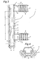
- Such plant carriers are placed in large numbers alongside each other in a greenhouse, as shown very diagrammatically in Fig. 3. Series 21 and 22 respectively are produced in this way.
- the wheels in this case move along (tubular) rails 23.
- the plant carrier can be moved along the rails mechanically or by hand.
- the plant carriers from such series 21, 22 are circulated. This can be done for all kinds of reasons, one of which is so that working personnel can carry out work on or check the condition of the plants in question. It may also be necessary to place them in a different position on account of the incidence of light, growing conditions, wider spacing, and so forth.
- Fig. 2 shows a conveyor belt 12, which is placed at an angle ⁇ of a number of degrees relative to the horizontal.
- a thickening edge 13 is provided on the lowest part. The thickening edge is such that during movement the wheels 8 pass easily over it, but, on the other hand, in a more or less static state the wheels do not move over it.
- a plant carrier 5 has been placed on conveyor belt 12 and is resting with the wheel furthest to the left against the elevation 13 and cannot move over it.
- two elevations 13 may be provided at a distance from each other on the conveyor belt, in which case the conveyor belt surface can be placed horizontally.
- Fig. 3 More details of the belt conveyor are shown in Fig. 3.
- the conveyor is provided with a diagrammatically indicated drive motor 14.
- Sensors 3 are provided on the frame 19 of the belt conveyor.
- the direction of movement is indicated by 20.
- the distance which such a conveyor belt moves is at least 7.5 metres, and this length is indicated by 'a'.
- one of the plant carriers from series 21 is moved in the direction of arrow 15.
- the plant carriers move along rails 23 until they are near conveyor belt 12.
- the elevation 13 is on the left-hand side, so that this obstacle does not have to be negotiated when the carrier 5 is travelling onto the conveyor belt 12.
- the carrier then goes into the position shown in Fig. 2.
- a movement in the direction of arrow 20 is performed by motor 14, controlled by a control element 4.
- the plant carrier 5 has reached the desired deposit position, its presence is detected by a sensor 3.
- the drive of the belt conveyor is interrupted by switching off motor 14. This switching off may be a gradual process if desired.
- the moment of switching off in that case is selected either by the presence of further sensors, or on the basis of the fact that during the run-down the plant carrier completes a further fixed distance, or it is selected by means of a counting mechanism in the control element, by means of which a slow-down occurs in good time.
- the plant carrier If the plant carrier has reached the correct position for being deposited, it is moved off the conveyor belt 12 in one way or another in the direction of arrow 16, and a new series 22 can be formed. This series may have different characteristics (mutual spacing) from those of series 21. During the movement with the belt conveyor the plant carrier can have work carried out on it.
- the wheel axle 17 extends at an angle to the horizontal, while the running face is provided with an opposing angle, so that the wheel ultimately rests horizontally on the surface of conveyor belt 12 or on rails 23. This produces line contact.
- the opposite wheel is in the form of a roller, so that it is not essential for the rails along which the plant carrier 6 runs to be accurately parallel. Slide blocks can be used instead of rollers.
Landscapes
- Engineering & Computer Science (AREA)
- Mechanical Engineering (AREA)
- Life Sciences & Earth Sciences (AREA)
- Environmental Sciences (AREA)
- Structure Of Belt Conveyors (AREA)
- Belt Conveyors (AREA)
- Handcart (AREA)
Priority Applications (4)
| Application Number | Priority Date | Filing Date | Title |
|---|---|---|---|
| DK04076192T DK1518802T3 (da) | 2004-04-19 | 2004-04-19 | Båndtransportör til transport af med hjul forsynede plantebærere |
| EP04076192A EP1518802B1 (de) | 2004-04-19 | 2004-04-19 | Bandförderer zum Transport von fahrbaren Pflanzenträgern |
| AT04076192T ATE330873T1 (de) | 2004-04-19 | 2004-04-19 | Bandförderer zum transport von fahrbaren pflanzenträgern |
| DE602004001305T DE602004001305T2 (de) | 2004-04-19 | 2004-04-19 | Bandförderer zum Transport von fahrbaren Pflanzenträgern |
Applications Claiming Priority (1)
| Application Number | Priority Date | Filing Date | Title |
|---|---|---|---|
| EP04076192A EP1518802B1 (de) | 2004-04-19 | 2004-04-19 | Bandförderer zum Transport von fahrbaren Pflanzenträgern |
Publications (2)
| Publication Number | Publication Date |
|---|---|
| EP1518802A1 true EP1518802A1 (de) | 2005-03-30 |
| EP1518802B1 EP1518802B1 (de) | 2006-06-21 |
Family
ID=34178728
Family Applications (1)
| Application Number | Title | Priority Date | Filing Date |
|---|---|---|---|
| EP04076192A Expired - Lifetime EP1518802B1 (de) | 2004-04-19 | 2004-04-19 | Bandförderer zum Transport von fahrbaren Pflanzenträgern |
Country Status (4)
| Country | Link |
|---|---|
| EP (1) | EP1518802B1 (de) |
| AT (1) | ATE330873T1 (de) |
| DE (1) | DE602004001305T2 (de) |
| DK (1) | DK1518802T3 (de) |
Cited By (2)
| Publication number | Priority date | Publication date | Assignee | Title |
|---|---|---|---|---|
| NL1028734C2 (nl) * | 2005-04-11 | 2006-10-12 | Totaal Techniek Frans Van Zaal | Transportband. |
| EP1733614A1 (de) * | 2005-06-17 | 2006-12-20 | W/M Systems B.V. | Mehrfach-Schienen-System und Verfahren zum Züchten eines Gewächses in einer Anbauwanne und Gärtnerei mit einer solchen |
Families Citing this family (1)
| Publication number | Priority date | Publication date | Assignee | Title |
|---|---|---|---|---|
| CN110100610A (zh) * | 2019-04-25 | 2019-08-09 | 北京城农科工科技发展有限公司 | 一种种植架长距离自动输送装置 |
Citations (1)
| Publication number | Priority date | Publication date | Assignee | Title |
|---|---|---|---|---|
| US5355621A (en) * | 1993-03-01 | 1994-10-18 | Yazaki Industrial Chemical Co., Ltd. | High-density type cultivation equipment |
-
2004
- 2004-04-19 DK DK04076192T patent/DK1518802T3/da active
- 2004-04-19 DE DE602004001305T patent/DE602004001305T2/de not_active Expired - Lifetime
- 2004-04-19 EP EP04076192A patent/EP1518802B1/de not_active Expired - Lifetime
- 2004-04-19 AT AT04076192T patent/ATE330873T1/de not_active IP Right Cessation
Patent Citations (1)
| Publication number | Priority date | Publication date | Assignee | Title |
|---|---|---|---|---|
| US5355621A (en) * | 1993-03-01 | 1994-10-18 | Yazaki Industrial Chemical Co., Ltd. | High-density type cultivation equipment |
Cited By (3)
| Publication number | Priority date | Publication date | Assignee | Title |
|---|---|---|---|---|
| NL1028734C2 (nl) * | 2005-04-11 | 2006-10-12 | Totaal Techniek Frans Van Zaal | Transportband. |
| WO2006110030A1 (en) * | 2005-04-11 | 2006-10-19 | Totaal Techniek Frans Van Zaal B.V. | Conveyor belt |
| EP1733614A1 (de) * | 2005-06-17 | 2006-12-20 | W/M Systems B.V. | Mehrfach-Schienen-System und Verfahren zum Züchten eines Gewächses in einer Anbauwanne und Gärtnerei mit einer solchen |
Also Published As
| Publication number | Publication date |
|---|---|
| ATE330873T1 (de) | 2006-07-15 |
| DE602004001305D1 (de) | 2006-08-03 |
| DK1518802T3 (da) | 2006-10-02 |
| EP1518802B1 (de) | 2006-06-21 |
| DE602004001305T2 (de) | 2006-11-02 |
Similar Documents
| Publication | Publication Date | Title |
|---|---|---|
| US4987992A (en) | Material transfer apparatus | |
| CN102119111B (zh) | 输送机总成 | |
| CA1319901C (en) | Arrangement for conveyor systems | |
| US4776453A (en) | Accumulating conveyor | |
| US4465417A (en) | System for handling vehicles of a revolving cableway in a parking station | |
| AU782125B2 (en) | Method and installation for exchanging roll supports on winding stations arranged in a row | |
| US4295774A (en) | Apparatus for automatically turning over and for storing sections of elastomeric material | |
| US4368822A (en) | Material handling method and apparatus | |
| US4320826A (en) | Material handling method and apparatus | |
| SE506782C2 (sv) | Anordning för horisontell uppbärning av lastbärare vilka bringas att röra sig cirkulerande i vertikalplanet | |
| US4598818A (en) | Accumulating conveyor | |
| EP1518802B1 (de) | Bandförderer zum Transport von fahrbaren Pflanzenträgern | |
| US4346799A (en) | Conveyor system with part transfer device | |
| EP2001770B1 (de) | Förderer zur förderung und pufferung von produkten | |
| ATE10826T1 (de) | Kommissionier-foerderanlage mit in transportrichtung hintereinander angeordneten uebergabestationen. | |
| US2359786A (en) | Can-weighing machine | |
| CA2534680C (en) | Conveyor transfer assembly | |
| EP0385711A2 (de) | Palettenförderer mit veränderlicher Geschwindigkeit | |
| US4795022A (en) | Biscuit conveyor | |
| NL1027412C2 (nl) | Inrichting voor het transporteren van een voorwerp. | |
| JP2003285925A (ja) | 搬送設備 | |
| CN211003279U (zh) | 一种自动化输送系统 | |
| FI72942B (fi) | Foerfarande och anordning foer att fraon ett justerbord upptransportera virkesstycken till en ovanfoer detta belaegen sorteringsplats. | |
| KR100221959B1 (ko) | 슬러지 제거장치 | |
| JP3443315B2 (ja) | 育苗箱の自動棚差し装置 |
Legal Events
| Date | Code | Title | Description |
|---|---|---|---|
| PUAI | Public reference made under article 153(3) epc to a published international application that has entered the european phase |
Free format text: ORIGINAL CODE: 0009012 |
|
| AK | Designated contracting states |
Kind code of ref document: A1 Designated state(s): AT BE BG CH CY CZ DE DK EE ES FI FR GB GR HU IE IT LI LU MC NL PL PT RO SE SI SK TR |
|
| AX | Request for extension of the european patent |
Extension state: AL HR LT LV MK |
|
| 17P | Request for examination filed |
Effective date: 20050928 |
|
| AKX | Designation fees paid |
Designated state(s): AT BE BG CH CY CZ DE DK EE ES FI FR GB GR HU IE IT LI LU MC NL PL PT RO SE SI SK TR |
|
| GRAP | Despatch of communication of intention to grant a patent |
Free format text: ORIGINAL CODE: EPIDOSNIGR1 |
|
| GRAS | Grant fee paid |
Free format text: ORIGINAL CODE: EPIDOSNIGR3 |
|
| GRAA | (expected) grant |
Free format text: ORIGINAL CODE: 0009210 |
|
| AK | Designated contracting states |
Kind code of ref document: B1 Designated state(s): AT BE BG CH CY CZ DE DK EE ES FI FR GB GR HU IE IT LI LU MC NL PL PT RO SE SI SK TR |
|
| PG25 | Lapsed in a contracting state [announced via postgrant information from national office to epo] |
Ref country code: IT Free format text: LAPSE BECAUSE OF FAILURE TO SUBMIT A TRANSLATION OF THE DESCRIPTION OR TO PAY THE FEE WITHIN THE PRESCRIBED TIME-LIMIT;WARNING: LAPSES OF ITALIAN PATENTS WITH EFFECTIVE DATE BEFORE 2007 MAY HAVE OCCURRED AT ANY TIME BEFORE 2007. THE CORRECT EFFECTIVE DATE MAY BE DIFFERENT FROM THE ONE RECORDED. Effective date: 20060621 Ref country code: BE Free format text: LAPSE BECAUSE OF FAILURE TO SUBMIT A TRANSLATION OF THE DESCRIPTION OR TO PAY THE FEE WITHIN THE PRESCRIBED TIME-LIMIT Effective date: 20060621 Ref country code: PL Free format text: LAPSE BECAUSE OF FAILURE TO SUBMIT A TRANSLATION OF THE DESCRIPTION OR TO PAY THE FEE WITHIN THE PRESCRIBED TIME-LIMIT Effective date: 20060621 Ref country code: SK Free format text: LAPSE BECAUSE OF FAILURE TO SUBMIT A TRANSLATION OF THE DESCRIPTION OR TO PAY THE FEE WITHIN THE PRESCRIBED TIME-LIMIT Effective date: 20060621 Ref country code: FI Free format text: LAPSE BECAUSE OF FAILURE TO SUBMIT A TRANSLATION OF THE DESCRIPTION OR TO PAY THE FEE WITHIN THE PRESCRIBED TIME-LIMIT Effective date: 20060621 Ref country code: CH Free format text: LAPSE BECAUSE OF FAILURE TO SUBMIT A TRANSLATION OF THE DESCRIPTION OR TO PAY THE FEE WITHIN THE PRESCRIBED TIME-LIMIT Effective date: 20060621 Ref country code: SI Free format text: LAPSE BECAUSE OF FAILURE TO SUBMIT A TRANSLATION OF THE DESCRIPTION OR TO PAY THE FEE WITHIN THE PRESCRIBED TIME-LIMIT Effective date: 20060621 Ref country code: CZ Free format text: LAPSE BECAUSE OF FAILURE TO SUBMIT A TRANSLATION OF THE DESCRIPTION OR TO PAY THE FEE WITHIN THE PRESCRIBED TIME-LIMIT Effective date: 20060621 Ref country code: AT Free format text: LAPSE BECAUSE OF FAILURE TO SUBMIT A TRANSLATION OF THE DESCRIPTION OR TO PAY THE FEE WITHIN THE PRESCRIBED TIME-LIMIT Effective date: 20060621 Ref country code: LI Free format text: LAPSE BECAUSE OF FAILURE TO SUBMIT A TRANSLATION OF THE DESCRIPTION OR TO PAY THE FEE WITHIN THE PRESCRIBED TIME-LIMIT Effective date: 20060621 Ref country code: RO Free format text: LAPSE BECAUSE OF FAILURE TO SUBMIT A TRANSLATION OF THE DESCRIPTION OR TO PAY THE FEE WITHIN THE PRESCRIBED TIME-LIMIT Effective date: 20060621 |
|
| REG | Reference to a national code |
Ref country code: GB Ref legal event code: FG4D |
|
| REG | Reference to a national code |
Ref country code: CH Ref legal event code: EP |
|
| REG | Reference to a national code |
Ref country code: IE Ref legal event code: FG4D |
|
| REF | Corresponds to: |
Ref document number: 602004001305 Country of ref document: DE Date of ref document: 20060803 Kind code of ref document: P |
|
| PG25 | Lapsed in a contracting state [announced via postgrant information from national office to epo] |
Ref country code: SE Free format text: LAPSE BECAUSE OF FAILURE TO SUBMIT A TRANSLATION OF THE DESCRIPTION OR TO PAY THE FEE WITHIN THE PRESCRIBED TIME-LIMIT Effective date: 20060921 |
|
| PG25 | Lapsed in a contracting state [announced via postgrant information from national office to epo] |
Ref country code: ES Free format text: LAPSE BECAUSE OF FAILURE TO SUBMIT A TRANSLATION OF THE DESCRIPTION OR TO PAY THE FEE WITHIN THE PRESCRIBED TIME-LIMIT Effective date: 20061002 |
|
| REG | Reference to a national code |
Ref country code: DK Ref legal event code: T3 |
|
| PG25 | Lapsed in a contracting state [announced via postgrant information from national office to epo] |
Ref country code: PT Free format text: LAPSE BECAUSE OF FAILURE TO SUBMIT A TRANSLATION OF THE DESCRIPTION OR TO PAY THE FEE WITHIN THE PRESCRIBED TIME-LIMIT Effective date: 20061121 |
|
| REG | Reference to a national code |
Ref country code: CH Ref legal event code: PL |
|
| PLBE | No opposition filed within time limit |
Free format text: ORIGINAL CODE: 0009261 |
|
| STAA | Information on the status of an ep patent application or granted ep patent |
Free format text: STATUS: NO OPPOSITION FILED WITHIN TIME LIMIT |
|
| EN | Fr: translation not filed | ||
| 26N | No opposition filed |
Effective date: 20070322 |
|
| PG25 | Lapsed in a contracting state [announced via postgrant information from national office to epo] |
Ref country code: GR Free format text: LAPSE BECAUSE OF FAILURE TO SUBMIT A TRANSLATION OF THE DESCRIPTION OR TO PAY THE FEE WITHIN THE PRESCRIBED TIME-LIMIT Effective date: 20060922 Ref country code: FR Free format text: LAPSE BECAUSE OF FAILURE TO SUBMIT A TRANSLATION OF THE DESCRIPTION OR TO PAY THE FEE WITHIN THE PRESCRIBED TIME-LIMIT Effective date: 20070504 |
|
| PG25 | Lapsed in a contracting state [announced via postgrant information from national office to epo] |
Ref country code: IE Free format text: LAPSE BECAUSE OF NON-PAYMENT OF DUE FEES Effective date: 20070419 |
|
| PG25 | Lapsed in a contracting state [announced via postgrant information from national office to epo] |
Ref country code: BG Free format text: LAPSE BECAUSE OF FAILURE TO SUBMIT A TRANSLATION OF THE DESCRIPTION OR TO PAY THE FEE WITHIN THE PRESCRIBED TIME-LIMIT Effective date: 20060921 |
|
| PG25 | Lapsed in a contracting state [announced via postgrant information from national office to epo] |
Ref country code: EE Free format text: LAPSE BECAUSE OF FAILURE TO SUBMIT A TRANSLATION OF THE DESCRIPTION OR TO PAY THE FEE WITHIN THE PRESCRIBED TIME-LIMIT Effective date: 20060621 |
|
| PG25 | Lapsed in a contracting state [announced via postgrant information from national office to epo] |
Ref country code: FR Free format text: LAPSE BECAUSE OF FAILURE TO SUBMIT A TRANSLATION OF THE DESCRIPTION OR TO PAY THE FEE WITHIN THE PRESCRIBED TIME-LIMIT Effective date: 20060621 |
|
| GBPC | Gb: european patent ceased through non-payment of renewal fee |
Effective date: 20080419 |
|
| PG25 | Lapsed in a contracting state [announced via postgrant information from national office to epo] |
Ref country code: MC Free format text: LAPSE BECAUSE OF NON-PAYMENT OF DUE FEES Effective date: 20070430 |
|
| PG25 | Lapsed in a contracting state [announced via postgrant information from national office to epo] |
Ref country code: GB Free format text: LAPSE BECAUSE OF NON-PAYMENT OF DUE FEES Effective date: 20080419 |
|
| PG25 | Lapsed in a contracting state [announced via postgrant information from national office to epo] |
Ref country code: LU Free format text: LAPSE BECAUSE OF NON-PAYMENT OF DUE FEES Effective date: 20070419 Ref country code: CY Free format text: LAPSE BECAUSE OF FAILURE TO SUBMIT A TRANSLATION OF THE DESCRIPTION OR TO PAY THE FEE WITHIN THE PRESCRIBED TIME-LIMIT Effective date: 20060621 |
|
| PG25 | Lapsed in a contracting state [announced via postgrant information from national office to epo] |
Ref country code: TR Free format text: LAPSE BECAUSE OF FAILURE TO SUBMIT A TRANSLATION OF THE DESCRIPTION OR TO PAY THE FEE WITHIN THE PRESCRIBED TIME-LIMIT Effective date: 20060621 Ref country code: HU Free format text: LAPSE BECAUSE OF FAILURE TO SUBMIT A TRANSLATION OF THE DESCRIPTION OR TO PAY THE FEE WITHIN THE PRESCRIBED TIME-LIMIT Effective date: 20061222 |
|
| PGFP | Annual fee paid to national office [announced via postgrant information from national office to epo] |
Ref country code: DK Payment date: 20150427 Year of fee payment: 12 |
|
| PGFP | Annual fee paid to national office [announced via postgrant information from national office to epo] |
Ref country code: DE Payment date: 20150630 Year of fee payment: 12 |
|
| REG | Reference to a national code |
Ref country code: DE Ref legal event code: R119 Ref document number: 602004001305 Country of ref document: DE |
|
| REG | Reference to a national code |
Ref country code: DK Ref legal event code: EBP Effective date: 20160430 |
|
| PG25 | Lapsed in a contracting state [announced via postgrant information from national office to epo] |
Ref country code: DE Free format text: LAPSE BECAUSE OF NON-PAYMENT OF DUE FEES Effective date: 20161101 |
|
| PG25 | Lapsed in a contracting state [announced via postgrant information from national office to epo] |
Ref country code: DK Free format text: LAPSE BECAUSE OF NON-PAYMENT OF DUE FEES Effective date: 20160430 |
|
| REG | Reference to a national code |
Ref country code: NL Ref legal event code: RC Free format text: DETAILS LICENCE OR PLEDGE: RIGHT OF PLEDGE, ESTABLISHED Name of requester: ABN AMRO BANK N.V. Effective date: 20180918 |
|
| PGFP | Annual fee paid to national office [announced via postgrant information from national office to epo] |
Ref country code: NL Payment date: 20200416 Year of fee payment: 17 |
|
| REG | Reference to a national code |
Ref country code: NL Ref legal event code: HC Owner name: CODEMA EMEA B.V.; NL Free format text: DETAILS ASSIGNMENT: CHANGE OF OWNER(S), CHANGE OF OWNER(S) NAME; FORMER OWNER NAME: W/M SYSTEMS B.V. Effective date: 20210702 |
|
| REG | Reference to a national code |
Ref country code: NL Ref legal event code: MM Effective date: 20210501 |
|
| PG25 | Lapsed in a contracting state [announced via postgrant information from national office to epo] |
Ref country code: NL Free format text: LAPSE BECAUSE OF NON-PAYMENT OF DUE FEES Effective date: 20210501 |