EP1518727A2 - Operating device of vehicle air conditioner - Google Patents
Operating device of vehicle air conditioner Download PDFInfo
- Publication number
- EP1518727A2 EP1518727A2 EP04022563A EP04022563A EP1518727A2 EP 1518727 A2 EP1518727 A2 EP 1518727A2 EP 04022563 A EP04022563 A EP 04022563A EP 04022563 A EP04022563 A EP 04022563A EP 1518727 A2 EP1518727 A2 EP 1518727A2
- Authority
- EP
- European Patent Office
- Prior art keywords
- dial
- unit
- operating
- temperature control
- air conditioner
- Prior art date
- Legal status (The legal status is an assumption and is not a legal conclusion. Google has not performed a legal analysis and makes no representation as to the accuracy of the status listed.)
- Granted
Links
Images


Classifications
-
- B—PERFORMING OPERATIONS; TRANSPORTING
- B60—VEHICLES IN GENERAL
- B60H—ARRANGEMENTS OF HEATING, COOLING, VENTILATING OR OTHER AIR-TREATING DEVICES SPECIALLY ADAPTED FOR PASSENGER OR GOODS SPACES OF VEHICLES
- B60H1/00—Heating, cooling or ventilating devices
- B60H1/00642—Control systems or circuits; Control members or indication devices for heating, cooling or ventilating devices
- B60H1/00985—Control systems or circuits characterised by display or indicating devices, e.g. voice simulators
-
- B—PERFORMING OPERATIONS; TRANSPORTING
- B60—VEHICLES IN GENERAL
- B60H—ARRANGEMENTS OF HEATING, COOLING, VENTILATING OR OTHER AIR-TREATING DEVICES SPECIALLY ADAPTED FOR PASSENGER OR GOODS SPACES OF VEHICLES
- B60H1/00—Heating, cooling or ventilating devices
- B60H1/00642—Control systems or circuits; Control members or indication devices for heating, cooling or ventilating devices
- B60H1/0065—Control members, e.g. levers or knobs
-
- B—PERFORMING OPERATIONS; TRANSPORTING
- B60—VEHICLES IN GENERAL
- B60K—ARRANGEMENT OR MOUNTING OF PROPULSION UNITS OR OF TRANSMISSIONS IN VEHICLES; ARRANGEMENT OR MOUNTING OF PLURAL DIVERSE PRIME-MOVERS IN VEHICLES; AUXILIARY DRIVES FOR VEHICLES; INSTRUMENTATION OR DASHBOARDS FOR VEHICLES; ARRANGEMENTS IN CONNECTION WITH COOLING, AIR INTAKE, GAS EXHAUST OR FUEL SUPPLY OF PROPULSION UNITS IN VEHICLES
- B60K20/00—Arrangement or mounting of change-speed gearing control devices in vehicles
- B60K20/02—Arrangement or mounting of change-speed gearing control devices in vehicles of initiating means
-
- B—PERFORMING OPERATIONS; TRANSPORTING
- B60—VEHICLES IN GENERAL
- B60K—ARRANGEMENT OR MOUNTING OF PROPULSION UNITS OR OF TRANSMISSIONS IN VEHICLES; ARRANGEMENT OR MOUNTING OF PLURAL DIVERSE PRIME-MOVERS IN VEHICLES; AUXILIARY DRIVES FOR VEHICLES; INSTRUMENTATION OR DASHBOARDS FOR VEHICLES; ARRANGEMENTS IN CONNECTION WITH COOLING, AIR INTAKE, GAS EXHAUST OR FUEL SUPPLY OF PROPULSION UNITS IN VEHICLES
- B60K35/00—Instruments specially adapted for vehicles; Arrangement of instruments in or on vehicles
-
- B—PERFORMING OPERATIONS; TRANSPORTING
- B60—VEHICLES IN GENERAL
- B60R—VEHICLES, VEHICLE FITTINGS, OR VEHICLE PARTS, NOT OTHERWISE PROVIDED FOR
- B60R16/00—Electric or fluid circuits specially adapted for vehicles and not otherwise provided for; Arrangement of elements of electric or fluid circuits specially adapted for vehicles and not otherwise provided for
-
- G—PHYSICS
- G05—CONTROLLING; REGULATING
- G05G—CONTROL DEVICES OR SYSTEMS INSOFAR AS CHARACTERISED BY MECHANICAL FEATURES ONLY
- G05G1/00—Controlling members, e.g. knobs or handles; Assemblies or arrangements thereof; Indicating position of controlling members
- G05G1/08—Controlling members for hand actuation by rotary movement, e.g. hand wheels
- G05G1/10—Details, e.g. of discs, knobs, wheels or handles
- G05G1/105—Details, e.g. of discs, knobs, wheels or handles comprising arrangements for illumination
Definitions
- the present invention relates to an operating device for operating an in-vehicle air conditioner in a vehicle.
- Some operating devices have a configuration in which a first operating portion 100 for controlling awindblowposition, a second operating portion 101 for controlling a wind blow rate and a third operating portion 102 for controlling a wind blow temperature are formed into a unit through the intermediary of a base 103 as shown in Fig. 10.
- the degree of freedom in the layout of the first to third operating portions 100 to 102 is so low that it is difficult to dispose the first to third operating portions 100 to 102 in accordance with the vehicle-side design.
- the present invention was developed in consideration of the aforementioned situation. It is an object of the invention to provide an operating device of a vehicle air conditioner having a high degree of freedom in layout.
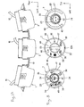
- harnesses 105 are electrically connected to the first to third operating portions 100 to 102 while dials 104 are not attached.
- the base 103 is attached to an instrument panel 106.
- a cluster panel 107 is screwed down to the first to third operating portions 102.
- the dials 104 are attached to the first to third operating portions 100 to 102 through through-holes 108 of the cluster panel 107 respectively.
- the first to third operating portions 100 to 102 have to be screwed down to the cluster panel 107.
- the installation cost is increased.
- the present invention was developed in consideration of the aforementioned situation. It is an object of the present invention to provide a method for installing the operating device, in which the installation cost can be reduced.
- a first configuration of the invention includes a first operating unit for controlling a wind blow position, a second operating unit for controlling a wind blow rate, and a third operating unit for controlling a wind blow temperature, wherein the first to third operating units are mechanically separated from one another.
- a second configuration of the invention includes the steps of electrically connecting harnesses to the first to third operating units, thereafter engaging the first to third operating units to a cluster panel, and attaching the cluster panel to an instrument panel.
- the first to third operating units are mechanically separated from one another. Accordingly, the degree of freedom in the layout of the first to third operating units is improved. It is therefore easy to dispose the first to third operating units in accordance with the vehicle-side design.
- the first to third operating units are engaged with the cluster panel, and the cluster panel is attached to the instrument panel. Accordingly, it is not necessary to screw the first to third operating units down to the cluster panel. Thus, the installation cost can be reduced.
- An operating device of a vehicle air conditioner is installed in the inside of a car.
- the operating device denotes an assembly of a plurality of operating units which are mechanically and electrically independent of one another.
- the plurality of operating units are fixed to an instrument panel of the car individually.
- the operating device is constituted by a mode selection unit corresponding to the first operating unit, a blower unit corresponding to the second operating unit, and a temperature control unit corresponding to the third operating unit.
- Each of the mode selection unit, the blower unit and the temperature control unit can be changed into a form corresponding to the specification of the air conditioner when a part of components thereof is replaced.
- the detailed configurations of the mode selection unit, the blower unit and the temperature control unit will be described below for each specification.
- the normal specification denotes a specification having both an air conditioner function and a heater function.
- the former air conditioner function is to control the temperature of the air based on heat exchange of the air, and to keep the inside of the car at a set temperature due to the temperature-controlled air blown into the inside of the car.
- the latter heater function is to heat the inside of the car based on the hot air blown into the inside of the car while using an engine or the like as a source for generating the hot air.
- a unit base 11 made from synthetic resin is fixed to the instrument panel of the car as shown in Fig. 3B.
- a cylindrical bearing 12 is formed integrally with the unit base 11.
- a cylindrical shaft 13 is rotatably fitted to the inner circumferential surface of the bearing 12.
- the shaft 13 is formed out of synthetic resin as its material.
- a cable base 14 is formed integrally with the shaft 13.
- a left end portion of a cable 15 is mechanically fixed to the cable base 14, while a right endportion of the cable 15 is movable in accordance with the cable base 14 rotating around the shaft 13.
- the shaft 13, the cable base 14 and the cable 15 constitute a cable unit 16.
- the right end portion of the cable 15 is mechanically connected to the air conditioner.
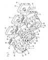
- a unit body 17 made from synthetic resin is fixed to the unit base 11 as shown in Fig. 3B.
- a plurality of mounting holes 18 are formed in the unit body 17.
- the plurality of mounting holes 18 are engaged with claw portions (not shown) of a cluster panel 19 (see Fig. 5) so that the unit body 17 is fixed to the cluster panel 19.
- a plurality of snap fit portions 20 are formed integrally with an outer circumferential portion of the unit body 17 as shown in Fig. 4.
- the snap fit portions 20 are disposed circumferentially on a common circular track and at an equal pitch.
- each snap fit portion 20 is constituted by a foot portion 21 extending in the front/rear direction and a protruding claw portion 22 located in a front end portion of the foot portion 21.
- a cylindrical dial base 23 is formed integrally with a front end portion of the unit body 17 as shown in Fig. 4.
- a dial 24 made from synthetic resin is fitted to an outer circumferential portion of the dial base 23 as shown in Fig. 3B, while a large-diameter ring-like seat portion 25 is formed integrally with a rear end portion of the dial 24 as shown in Fig. 4.
- a plurality of claw portions 22 are in engagement with the seat portion 25 as shown in Fig. 3B.
- a gear portion 26 is formed integrally with the inner circumferential surface of the dial 24.
- a large-diameter portion 28 of a main driving gear 27 is geared with the gear portion 26.
- the main driving gear 27 is formed out of synthetic resin as its material.
- the main driving gear 27 has the gear-like large-diameter portion 28 and a gear-like small-diameter portion 29 integrally.
- the main driving gear 27 is attached to the unit body 17 rotatably around a shaft 30. When the dial 24 is operated, the main driving gear 27 rotates relatively to the dial 24.
- a driven gear 31 made from synthetic resin is geared with the small-diameter portion 29 of the main driving gear 27.
- the driven gear 31 is fixed to the shaft 13 so that the driven gear 31 cannot rotate.
- the dial 24 is operated, the driven gear 31 is operated to rotate through the main driving gear 27 so as to operate and move the cable 15. That is, the main driving gear 27 has a function as a transmission member for transmitting the operating force of the dial 24 to the driven gear 31 and a regulation member for regulating the rotation quantity of the driven gear 31 with respect to the operating quantity of the dial 24.
- the ratio of the rotation quantity of the driven gear 31 to the operating quantity of the dial 24 is set to be "1:1".
- An arc-shaped opening portion 32 is formed in the dial 24 as shown in Fig. 4.
- a mark plate 33 made from synthetic resin is fixed into the opening portion 32 as shown in Fig. 3B.
- a plurality of mode marks 34 are fixed to the mark plate 33 as shown in Fig. 3A.
- a triangular pointer 35 is fixed to the front surface of the dial base 23 so as to be located in an inner circumferential portion of the dial 24.
- the pointer 35 indicates the wind blow position in cooperation with the mode marks 34.
- the dial 24 is operated to rotate to oppose one of the plurality of mode marks 34 to the outer circumferential portion of the pointer 35, the cable 15 moves in accordance with the rotation position of the dial 24.
- the air conditioner selectively opens an air outlet corresponding to the selected one of the mode marks 34.
- a switch board 36 made from synthetic resin is fixed into the unit body 17 as shown in Fig. 3B.
- a switch 37 is mechanically fixed to the switchboard 36.
- the switch 37 is made of a lock-type push-push switch which is self-held in an on-state in which the plunger 38 has been operated to be pushed backward.
- a knob holder 39 made from synthetic resin is mechanically coupled with the plunger 38.
- a knob 40 made from synthetic resin is fixed to the knob holder 39.
- a rear defogger mark 41 is fixed to the knob 40 as shown in Fig. 3A.
- the knob 40 is received in the dial base 23 so that the knob 40 cannot rotate.
- the knob 40 is disposed in a central portion of the dial 24 as shown in Fig. 3A.
- the knob 40 is designed to be able to slide in the front/rear direction relatively to the dial 24.
- a front end portion of a lens 42 is inserted into the knob 40 as shown in Fig. 3B.
- the lens 42 is formed out of colored transparent synthetic resin as its material, and fixed to the knob 40.
- a lamp 43 and an LED 44 are mechanically fixed to the switch board 36.
- the lamp 43 and the LED 44 are disposed at the rear of the rear defogger mark 41 and the lens 42 and in opposition thereto respectively.
- the rear defogger mark 41 and the lens 42 are illuminated.
- a plurality of lamps (not shown) are fixed to the switch board 36 so as to be located at the rear of the plurality of mode marks 34 so that the plurality of mode marks 34 are illuminated by the plurality of rear lamps turned on, respectively.
- a light shield plate 45 is formed integrally with the knob 40 between the rear defogger mark 41 and the lens 42.
- the light shield plate 45 has a rear end portion wrapping the LED 44 in the up/down direction.
- the light shield plate 45 prevents incident light from the lamp 43 and incident light from the LED 44 from being mixed with each other, and concentrates the incident light from the lamp 43 and the incident light from the LED 44 on the rear defogger mark 41 and the lens 42 respectively.
- a plurality of conductive plates 46 are mechanically fixed to the switch board 36 so that the switch 37, the lamp 43, the LED 44 and the plurality of lamps are electrically connected to the conductive plates 46 respectively.
- a connector housing 47 is formed integrally with the switch board 36 as shown in Fig. 2. One-end portions of the plurality of conductive plates 46 are received in the connector housing 47.
- a connector 49 of a harness 48 is fitted to the connector housing 47 so that the switch 37, the lamp 43, the LED 44 and the plurality of lamps are electrically connected to a defogger device (not shown) through the connector 49 of the harness 48 and lead wires 50.
- the defogger device heats the rear glass to thereby defog it.
- the switch 37 is turned on.
- the defogger device actuates its defogger function for a rear glass. Then, driving power is supplied to the LED 44 so that the lens 42 is illuminated. Thus, a driver is informed of the fact that the rear defogger function has been turned on. 2-2. Blower Unit 2
- the blower unit 2 shares a large number of constituent parts with the mode selection unit 1.
- the blower unit 2 has points of difference from the mode selection unit 1 as follows.
- a dial base 51 made from synthetic resin is fixed to a unit body 17.
- An outer dial 52 made from synthetic resin is fitted to the outer circumferential surface of the dial base 51.
- a large-diameter seat portion 53 is engaged with a plurality of claw portions 22 of the unit body 17 so that the outer dial 52 can rotate but cannot fall out.
- a pointer 53A is fixed to the outer dial 52.
- a gear portion 26 is formed integrally with the inner circumferential portion of the outer dial 52. The gear portion 26 is geared with a large-diameter portion 28 of a main driving gear 27.
- An arc-shaped opening portion 54 is formed in the dial base 51.
- a mark plate 55 made from synthetic resin is fixed into the opening portion 54 as shown in Fig. 6A.
- Two intake marks 56 are fixed to the mark plate 55.
- An inner dial 57 made from synthetic resin is attached to the inner circumferential surface of the dial base 51 as shown in Fig. 6A.
- a protruding dial operating portion 58 is formed integrally with the front surface of the inner dial 57.
- a front end portion of a lens 59 serving as a pointer is fixed to the dial operating portion 58 as shown in Fig. 6B.
- a shaft 61 of a contact holder 60 is fixed to the inner dial 57.
- Amovable contact 63 is coupled with the contact holder 60 through a contact spring 62.
- the movable contact 63 is pressed onto a fixed contact 64 by a spring force of the contact spring 62.
- the fixed contact 64 together with the movable contact 63 forms a blower switch 65.
- the fixed contact 64 is fixed to the switch board 36.
- a connector 49 of a harness 48 is fitted to a housing 47 so that the blower switch 65 is electrically connected to the air conditioner.
- the air conditioner sets the wind blow rate based on an output signal from the blower switch 65.
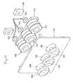
- a plurality of blower marks 66 are fixed to the mark plate 55 as shown in Fig. 6A.
- the plurality of blower marks 66 and the plurality of intake marks 56 are illuminatedwith a plurality of lamps of the switch board 36 when these lamps are turned on.
- the inner dial 57 is operated to rotate to selectively oppose the lens 59 to the inner circumferential portion of one of the blower marks 66, a signal corresponding to the rotation position of the inner dial 57 is outputted from the blower switch 65.
- the air conditioner sets the wind blow rate based on the output signal from the blower switch 65 so as to control the wind blow rate to have a value corresponding to the selection one of the blower marks 66. 2-3. Temperature Control Unit 3
- the temperature control unit 3 shares a large number of constituent parts with the mode selection unit 1. Points of difference from the mode selection unit 1 will be described below.
- An air conditioning mark 67 is fixed to a knob 40 so as to be located in front of a lamp 43 as shown in Fig. 2.
- the air conditioner detects the off state of a switch 37, and selectively makes its heater function valid. In this state, an LED 44 is turned off so as to inform the driver of the off state of the air conditioner function.
- the air conditioner detects the on state of the switch 37, and selectively makes the air conditioner function valid. In this on state, the LED 44 is turned on so that the lens 42 is illuminated. Thus, the driver is informed of the on state of the air conditioner function.
- Two temperature marks 68 are fixed to a dial 24.
- the dial 24 When the dial 24 is operated to rotate to oppose a predetermined position of one of the temperature marks 68 to the outer circumferential portion of a pointer 35, a cable 15 moves in accordance with the rotation position of the dial 24, and the air conditioner sets the wind blow temperature in accordance with the moving position of the cable 15.
- the heaterless specification denotes a specification having only the air conditioner function.
- a mode selection unit 1 and a blower unit 2 having the same configurations as those in the normal specification are used, but a temperature control unit 3 having a different configuration from that in the normal specification is used. Description will be made below about the temperature control unit 3.
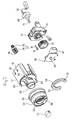
- a volume 69 is fixed to a unit base 11 as shown in Fig. 7.
- the volume 69 is electrically connected to the air conditioner through a harness 70.
- a driven gear 31 is fixed to a shaft 71 of the volume 69.
- the driven gear 31 is mechanically coupled with a gear portion 26 of a dial 24 through a main driving gear 27.
- the dial 24 is operated, the shaft 71 is operated to rotate through the main driving gear 27 and the driven gear 31.
- Arecess portion (not shown) is formed in a rear end portion of the driven gear 31.
- a temperance spring 74 made of a compression coil spring is received in the recess portion.
- a temperance ball 75 is fixed to a rear endportion of the temperance spring 74.
- the temperance ball 75 is pressed onto a temperance portion 76 by a spring force of the temperance spring 74.
- the temperance portion 76 denotes an irregular portion formed integrally with the front surface of the unit base 11.
- An off mark 72 is fixed to a mark plate 33 of the dial 24.
- an output signal from the volume 69 reaches a threshold value, so that the air conditioner function of the air conditioner is turned off.
- a temperature mark 68 is provided in the mark plate 33.
- the output signal from the volume 69 escapes from the threshold value, so that the air conditioner function of the air conditioner is turned on.
- the output signal of the volume 69 has magnitude corresponding to the rotation position of the dial 24, and the air conditioner controls the wind blow temperature in accordance with the magnitude of the output signal. That is, the dial 24 has both the on/off function of turning on/off the air conditioner function, and the temperature control function.
- a dummy knob 73 is attached to a central portion of the dial 24 so that the dummy knob 73 cannot be operated.
- the switch 37, the LED 44 and the knob holder 39 are absent.
- the air-conditionerless specification denotes a specification having only the heater function.
- a mode selection unit 1 and a blower unit 2 having the same configurations as those in the normal specification are used, but a temperature control unit 3 having a different configuration from that in the normal configuration is used.
- a dummy knob 73 is attached to a central portion of a dial 24 so that the dummy knob 73 cannot be operated, and the switch board 36 and the knob holder 39 are absent.
- the blow temperature from a heater is controlled by the dial 24 of the temperature control unit 3, the blow position is selected by a dial 24 of the mode selection unit 1, and the blow rate is controlled by an inner dial 57 of the blower unit 2.
- the heaterless and air-conditionerless specification denotes a specification having only a function of blowing a normal-temperature wind into the inside of the car.
- a mode selection unit 1 and a blower unit 2 having the same configurations as those in the normal specification are used, but a temperature control unit 3 having a different configuration from that in the normal configuration is used.
- the temperature control unit 3 is, as shown in Fig. 9, constituted by a dummy knob having mounting holes 18 to be engaged with claw portions of a cluster panel 19 so that the dummy knob cannot be operated.
- the mode selection unit 1, the blower unit 2 and the temperature control unit 3 are arranged as operating mechanisms mechanically separated from one another. Accordingly, the degree of freedom in the layout of the mode selection unit 1 to the temperature control unit 3 is improved so that the mode selection unit 1 to the temperature control unit 3 can be disposed along the arc-shaped cluster panel 19 (see Fig. 1A), disposed in a triangular shape or aligned lengthwise. It is therefore easy to dispose the mode selection unit 1 to the temperature control unit 3 in accordance with the car-side design.
- the mode selection unit 1 to the temperature control unit 3 are engaged with the cluster panel 19, and the cluster panel 19 is attached to the instrument panel 74. Accordingly, it is not necessary to screw the mode selection unit 1 to the temperature control unit 3 down to the cluster panel 19. Thus, the installation cost can be reduced.
- the embodiment shows an example in which the air conditioner is operatedmechanically through the cables 15 using the mode selection unit 1 having the normal specification, the heaterless specification, the air-conditionerless specification or the heaterless and air-conditionerless specification, the blower unit 2 having the normal specification, the heaterless specification, the air-conditionerless specification or the heaterless and air-conditionerless specification, and the temperature control unit 3 having the normal specification.
- the invention is not limited to such an example.
- a temperature control unit 3 having the heaterless specification using an electronic device such as the volume 69 for electrically operating the air conditioner may be used.
- the temperance spring 74 and the temperance ball 75 are provided in the driven gear 31, and the temperance portion 76 is provided in the unit base 11.
- the invention is not limited to such a configuration.
- a temperance mechanism constituted by the temperance spring 74, the temperance ball 75 and the temperance portion 76 may be built in the inside of the volume 69.
Landscapes
- Engineering & Computer Science (AREA)
- Mechanical Engineering (AREA)
- Physics & Mathematics (AREA)
- Thermal Sciences (AREA)
- Chemical & Material Sciences (AREA)
- Combustion & Propulsion (AREA)
- Transportation (AREA)
- General Physics & Mathematics (AREA)
- Automation & Control Theory (AREA)
- Air-Conditioning For Vehicles (AREA)
- Mechanical Control Devices (AREA)
Abstract
Description
Claims (2)
- An operating device of a vehicle air-conditioner, comprising:wherein the first to third operating units are mechanically separated from one another.a first operating unit for controlling a wind blow position;a second operating unit for controlling a wind blow rate; anda third operating unit for controlling a wind blow temperature,
- A method of installing an operating device of a vehicle air-conditioner that includes: a first operating unit for controlling a wind blow position; a second operating unit for controlling a wind blow rate; and a third operating unit for controlling a wind blow temperature, wherein the first to third operating units are mechanically separated from one another, the method comprising the steps of:electrically connecting harnesses to the first to third operating units;after the connecting step, engaging the first to third operating units to a cluster panel; andattaching the cluster panel to an instrument panel.
Applications Claiming Priority (2)
| Application Number | Priority Date | Filing Date | Title |
|---|---|---|---|
| JP2003332057A JP2005096579A (en) | 2003-09-24 | 2003-09-24 | Operating device for vehicular air-conditioner |
| JP2003332057 | 2003-09-24 |
Publications (3)
| Publication Number | Publication Date |
|---|---|
| EP1518727A2 true EP1518727A2 (en) | 2005-03-30 |
| EP1518727A3 EP1518727A3 (en) | 2006-02-08 |
| EP1518727B1 EP1518727B1 (en) | 2008-11-12 |
Family
ID=34191457
Family Applications (1)
| Application Number | Title | Priority Date | Filing Date |
|---|---|---|---|
| EP04022563A Expired - Lifetime EP1518727B1 (en) | 2003-09-24 | 2004-09-22 | Operating device of vehicle air conditioner |
Country Status (6)
| Country | Link |
|---|---|
| US (1) | US7811160B2 (en) |
| EP (1) | EP1518727B1 (en) |
| JP (1) | JP2005096579A (en) |
| KR (1) | KR20050030232A (en) |
| CN (1) | CN1601426B (en) |
| DE (1) | DE602004017682D1 (en) |
Cited By (1)
| Publication number | Priority date | Publication date | Assignee | Title |
|---|---|---|---|---|
| WO2009153185A1 (en) * | 2008-06-20 | 2009-12-23 | Valeo Systemes Thermiques | Control device for controlling functions on a motor vehicle control panel and corresponding control panel |
Families Citing this family (18)
| Publication number | Priority date | Publication date | Assignee | Title |
|---|---|---|---|---|
| US7414206B2 (en) * | 2005-01-25 | 2008-08-19 | Calsonic Kansei Corporation | Control panel for vehicle air conditioner |
| JP4636545B2 (en) * | 2005-08-02 | 2011-02-23 | 株式会社東海理化電機製作所 | Air conditioning switch device for vehicles |
| JP5209937B2 (en) * | 2007-10-26 | 2013-06-12 | 株式会社東海理化電機製作所 | Operating device |
| KR100895287B1 (en) * | 2007-11-20 | 2009-04-29 | 우리산업 주식회사 | Control assembly with initial position setting structure |
| CN101596850B (en) * | 2008-06-04 | 2012-07-04 | 浙江三花汽车零部件股份有限公司 | Air intake regulation device |
| JP5117952B2 (en) * | 2008-07-24 | 2013-01-16 | 株式会社東海理化電機製作所 | Operating device |
| JP5117994B2 (en) * | 2008-10-24 | 2013-01-16 | 株式会社東海理化電機製作所 | Dial device |
| JP5177038B2 (en) * | 2009-03-19 | 2013-04-03 | 住友電装株式会社 | Dial operation device for vehicle |
| JP5346882B2 (en) * | 2010-06-17 | 2013-11-20 | 株式会社東海理化電機製作所 | Operating device |
| JP5571474B2 (en) * | 2010-06-18 | 2014-08-13 | 株式会社東海理化電機製作所 | Operating device |
| JP5508168B2 (en) * | 2010-06-30 | 2014-05-28 | 株式会社東海理化電機製作所 | Operating device |
| JP5508231B2 (en) * | 2010-11-15 | 2014-05-28 | 株式会社東海理化電機製作所 | Operating device |
| JP5635936B2 (en) | 2011-03-31 | 2014-12-03 | 株式会社東海理化電機製作所 | Operating device |
| JP5981146B2 (en) | 2012-01-10 | 2016-08-31 | 株式会社東海理化電機製作所 | Operating device |
| US9728356B2 (en) * | 2014-09-12 | 2017-08-08 | Denso International America, Inc. | Projected knob device |
| JP6607573B2 (en) * | 2016-08-10 | 2019-11-20 | オムロンオートモーティブエレクトロニクス株式会社 | Switch device |
| JP7156619B2 (en) * | 2018-07-13 | 2022-10-19 | 株式会社東海理化電機製作所 | shift device |
| KR102805168B1 (en) * | 2020-03-30 | 2025-05-08 | 현대자동차주식회사 | Air vent device for vehicle |
Family Cites Families (21)
| Publication number | Priority date | Publication date | Assignee | Title |
|---|---|---|---|---|
| JPS4118428Y1 (en) | 1964-01-29 | 1966-08-27 | ||
| JPS5980929A (en) | 1982-10-29 | 1984-05-10 | Matsushita Electronics Corp | Manufacture of semiconductor device |
| DE3332984A1 (en) * | 1983-09-13 | 1985-03-28 | Aurora Konrad G. Schulz Gmbh & Co, 6933 Mudau | ARRANGEMENT OF ACTUATORS, ESPECIALLY FOR DEVICES FOR HEATING AND VENTILATING DRIVER'S CABINS, PASSENGER ROOMS OR THE LIKE. IN COMMERCIAL VEHICLES |
| JPS62169428A (en) | 1986-01-22 | 1987-07-25 | Hitachi Tobu Semiconductor Ltd | Sealing method |
| DE3910489A1 (en) * | 1989-03-31 | 1990-10-04 | Siemens Ag | METHOD FOR FRESH AIR CONTROL IN THE MID-LEVEL OF A MOTOR VEHICLE AND DEVICE FOR IMPLEMENTING THE METHOD |
| JP2849129B2 (en) | 1989-10-11 | 1999-01-20 | 旭硝子株式会社 | Method for producing 1,3-dichloro-1,1,2,2,3-pentafluoropropane |
| JP3127746B2 (en) | 1994-11-29 | 2001-01-29 | ウシオ電機株式会社 | Paper dryer |
| US5838221A (en) * | 1996-01-29 | 1998-11-17 | Delco Electronics Corporation | Motor control system and control head |
| FR2754077B1 (en) * | 1996-09-30 | 1998-12-04 | Valeo Electronique | DEVICE FOR MOUNTING A ROTARY OPERATING KNOB ON A CONTROL PANEL |
| JP3367842B2 (en) | 1996-10-30 | 2003-01-20 | 日野自動車株式会社 | Mounting structure of heater control device |
| SE9704803L (en) * | 1997-12-22 | 1998-11-23 | Scania Cv Ab | Operating device of a ventilation device in a vehicle |
| JP4118428B2 (en) | 1998-12-25 | 2008-07-16 | 松下電器産業株式会社 | Control method of electric resin molding machine |
| DE19926651C1 (en) * | 1999-06-11 | 2000-12-14 | Opel Adam Ag | Automotive sensors |
| JP3789733B2 (en) * | 2000-07-06 | 2006-06-28 | アルプス電気株式会社 | Compound operation switch |
| JP2002052919A (en) * | 2000-08-09 | 2002-02-19 | Denso Corp | Vehicle air conditioner |
| JP2002087048A (en) | 2000-09-12 | 2002-03-26 | Calsonic Kansei Corp | Control device for automobile air-conditioning system |
| US6626232B1 (en) * | 2000-09-22 | 2003-09-30 | Delphi Technologies, Inc. | Mechanical control head system |
| JP3834473B2 (en) * | 2000-11-30 | 2006-10-18 | 株式会社東海理化電機製作所 | Vehicle operation switch unit |
| EP1228908B1 (en) * | 2001-01-31 | 2008-06-11 | Kabushiki Kaisha Tokai Rika Denki Seisakusho | Controller unit of automotive air conditioning apparatus |
| US6517138B1 (en) * | 2001-08-29 | 2003-02-11 | Deere & Company | Recessed air conditioning controls for a utility vehicle |
| US7140271B2 (en) * | 2003-03-04 | 2006-11-28 | Illinois Tool Works Inc | Damper and an assembly therewith |
-
2003
- 2003-09-24 JP JP2003332057A patent/JP2005096579A/en active Pending
-
2004
- 2004-09-21 CN CN2004100826003A patent/CN1601426B/en not_active Expired - Fee Related
- 2004-09-22 EP EP04022563A patent/EP1518727B1/en not_active Expired - Lifetime
- 2004-09-22 DE DE602004017682T patent/DE602004017682D1/en not_active Expired - Lifetime
- 2004-09-23 US US10/947,359 patent/US7811160B2/en active Active
- 2004-09-24 KR KR1020040076878A patent/KR20050030232A/en not_active Ceased
Cited By (2)
| Publication number | Priority date | Publication date | Assignee | Title |
|---|---|---|---|---|
| WO2009153185A1 (en) * | 2008-06-20 | 2009-12-23 | Valeo Systemes Thermiques | Control device for controlling functions on a motor vehicle control panel and corresponding control panel |
| FR2932727A1 (en) * | 2008-06-20 | 2009-12-25 | Valeo Systemes Thermiques | CONTROL DEVICE FOR CONTROLLING FUNCTIONS OF A CONTROL PANEL FOR A MOTOR VEHICLE AND CONTROL PANEL THEREFOR |
Also Published As
| Publication number | Publication date |
|---|---|
| KR20050030232A (en) | 2005-03-29 |
| JP2005096579A (en) | 2005-04-14 |
| EP1518727A3 (en) | 2006-02-08 |
| EP1518727B1 (en) | 2008-11-12 |
| CN1601426A (en) | 2005-03-30 |
| CN1601426B (en) | 2010-08-04 |
| US7811160B2 (en) | 2010-10-12 |
| DE602004017682D1 (en) | 2008-12-24 |
| US20050098642A1 (en) | 2005-05-12 |
Similar Documents
| Publication | Publication Date | Title |
|---|---|---|
| EP1518727B1 (en) | Operating device of vehicle air conditioner | |
| EP1518726B1 (en) | Operating device of air conditioner for vehicle | |
| US7163455B2 (en) | Operating device for air conditioner for vehicle | |
| EP1884857B1 (en) | Rotary knob with a display | |
| US6667446B1 (en) | Rotary knob device with a key function | |
| KR20110046445A (en) | A control device for controlling the function of the vehicle control panel and a corresponding control panel | |
| US8967021B2 (en) | Operating device | |
| JP4087245B2 (en) | Control operation device for vehicle air conditioning | |
| CN101539325A (en) | Rotary switch assembly for air conditioner in vehicle | |
| JP4263572B2 (en) | Operation device for vehicle air conditioner | |
| KR101330108B1 (en) | Controller of air conditioning system for automotive vehicles | |
| JP4064153B2 (en) | Control operation device for vehicle air conditioning | |
| KR101105078B1 (en) | Button Structure of Vehicle Controller | |
| KR101054751B1 (en) | Dual dial device for air conditioning control of automobiles | |
| US7411141B2 (en) | Combination switch | |
| KR200275394Y1 (en) | Airconditioning controller with power connecting device for use of car | |
| JP2009113545A (en) | Operating device for air-conditioning for vehicle | |
| JP4300152B2 (en) | Switch mechanism of rotary operation device | |
| JPH08216734A (en) | Device for operating elements in the driver's seat of a motor vehicle | |
| JP2013052829A (en) | Operating device | |
| KR20040086862A (en) | Structure for raising the visibility of compound switching equipment for heater control in vehicle |
Legal Events
| Date | Code | Title | Description |
|---|---|---|---|
| PUAI | Public reference made under article 153(3) epc to a published international application that has entered the european phase |
Free format text: ORIGINAL CODE: 0009012 |
|
| AK | Designated contracting states |
Kind code of ref document: A2 Designated state(s): AT BE BG CH CY CZ DE DK EE ES FI FR GB GR HU IE IT LI LU MC NL PL PT RO SE SI SK TR |
|
| AX | Request for extension of the european patent |
Extension state: AL HR LT LV MK |
|
| PUAL | Search report despatched |
Free format text: ORIGINAL CODE: 0009013 |
|
| AK | Designated contracting states |
Kind code of ref document: A3 Designated state(s): AT BE BG CH CY CZ DE DK EE ES FI FR GB GR HU IE IT LI LU MC NL PL PT RO SE SI SK TR |
|
| AX | Request for extension of the european patent |
Extension state: AL HR LT LV MK |
|
| 17P | Request for examination filed |
Effective date: 20060314 |
|
| AKX | Designation fees paid |
Designated state(s): CZ DE FR GB SE |
|
| 17Q | First examination report despatched |
Effective date: 20060428 |
|
| GRAP | Despatch of communication of intention to grant a patent |
Free format text: ORIGINAL CODE: EPIDOSNIGR1 |
|
| GRAS | Grant fee paid |
Free format text: ORIGINAL CODE: EPIDOSNIGR3 |
|
| GRAA | (expected) grant |
Free format text: ORIGINAL CODE: 0009210 |
|
| AK | Designated contracting states |
Kind code of ref document: B1 Designated state(s): CZ DE FR GB SE |
|
| REG | Reference to a national code |
Ref country code: GB Ref legal event code: FG4D |
|
| REF | Corresponds to: |
Ref document number: 602004017682 Country of ref document: DE Date of ref document: 20081224 Kind code of ref document: P |
|
| REG | Reference to a national code |
Ref country code: SE Ref legal event code: TRGR |
|
| PLBE | No opposition filed within time limit |
Free format text: ORIGINAL CODE: 0009261 |
|
| STAA | Information on the status of an ep patent application or granted ep patent |
Free format text: STATUS: NO OPPOSITION FILED WITHIN TIME LIMIT |
|
| 26N | No opposition filed |
Effective date: 20090813 |
|
| REG | Reference to a national code |
Ref country code: FR Ref legal event code: PLFP Year of fee payment: 13 |
|
| REG | Reference to a national code |
Ref country code: FR Ref legal event code: PLFP Year of fee payment: 14 |
|
| PGFP | Annual fee paid to national office [announced via postgrant information from national office to epo] |
Ref country code: DE Payment date: 20170920 Year of fee payment: 14 Ref country code: CZ Payment date: 20170828 Year of fee payment: 14 Ref country code: FR Payment date: 20170810 Year of fee payment: 14 Ref country code: GB Payment date: 20170920 Year of fee payment: 14 |
|
| PGFP | Annual fee paid to national office [announced via postgrant information from national office to epo] |
Ref country code: SE Payment date: 20170912 Year of fee payment: 14 |
|
| REG | Reference to a national code |
Ref country code: DE Ref legal event code: R119 Ref document number: 602004017682 Country of ref document: DE |
|
| PG25 | Lapsed in a contracting state [announced via postgrant information from national office to epo] |
Ref country code: CZ Free format text: LAPSE BECAUSE OF NON-PAYMENT OF DUE FEES Effective date: 20180922 |
|
| REG | Reference to a national code |
Ref country code: SE Ref legal event code: EUG |
|
| GBPC | Gb: european patent ceased through non-payment of renewal fee |
Effective date: 20180922 |
|
| PG25 | Lapsed in a contracting state [announced via postgrant information from national office to epo] |
Ref country code: SE Free format text: LAPSE BECAUSE OF NON-PAYMENT OF DUE FEES Effective date: 20180923 |
|
| PG25 | Lapsed in a contracting state [announced via postgrant information from national office to epo] |
Ref country code: DE Free format text: LAPSE BECAUSE OF NON-PAYMENT OF DUE FEES Effective date: 20190402 |
|
| PG25 | Lapsed in a contracting state [announced via postgrant information from national office to epo] |
Ref country code: FR Free format text: LAPSE BECAUSE OF NON-PAYMENT OF DUE FEES Effective date: 20180930 |
|
| PG25 | Lapsed in a contracting state [announced via postgrant information from national office to epo] |
Ref country code: GB Free format text: LAPSE BECAUSE OF NON-PAYMENT OF DUE FEES Effective date: 20180922 |