EP1518606A2 - Flotationsvorrichtung zur Abtrennung der Mineralien vom Sand. - Google Patents
Flotationsvorrichtung zur Abtrennung der Mineralien vom Sand. Download PDFInfo
- Publication number
- EP1518606A2 EP1518606A2 EP04104550A EP04104550A EP1518606A2 EP 1518606 A2 EP1518606 A2 EP 1518606A2 EP 04104550 A EP04104550 A EP 04104550A EP 04104550 A EP04104550 A EP 04104550A EP 1518606 A2 EP1518606 A2 EP 1518606A2
- Authority
- EP
- European Patent Office
- Prior art keywords
- flotation
- basin
- minerals
- sand
- foam
- Prior art date
- Legal status (The legal status is an assumption and is not a legal conclusion. Google has not performed a legal analysis and makes no representation as to the accuracy of the status listed.)
- Withdrawn
Links
Images
Classifications
-
- B—PERFORMING OPERATIONS; TRANSPORTING
- B03—SEPARATION OF SOLID MATERIALS USING LIQUIDS OR USING PNEUMATIC TABLES OR JIGS; MAGNETIC OR ELECTROSTATIC SEPARATION OF SOLID MATERIALS FROM SOLID MATERIALS OR FLUIDS; SEPARATION BY HIGH-VOLTAGE ELECTRIC FIELDS
- B03D—FLOTATION; DIFFERENTIAL SEDIMENTATION
- B03D1/00—Flotation
- B03D1/02—Froth-flotation processes
- B03D1/028—Control and monitoring of flotation processes; computer models therefor
-
- B—PERFORMING OPERATIONS; TRANSPORTING
- B01—PHYSICAL OR CHEMICAL PROCESSES OR APPARATUS IN GENERAL
- B01D—SEPARATION
- B01D21/00—Separation of suspended solid particles from liquids by sedimentation
- B01D21/02—Settling tanks with single outlets for the separated liquid
-
- B—PERFORMING OPERATIONS; TRANSPORTING
- B01—PHYSICAL OR CHEMICAL PROCESSES OR APPARATUS IN GENERAL
- B01D—SEPARATION
- B01D21/00—Separation of suspended solid particles from liquids by sedimentation
- B01D21/24—Feed or discharge mechanisms for settling tanks
- B01D21/245—Discharge mechanisms for the sediments
- B01D21/2461—Positive-displacement pumps; Screw feeders; Trough conveyors
-
- B—PERFORMING OPERATIONS; TRANSPORTING
- B03—SEPARATION OF SOLID MATERIALS USING LIQUIDS OR USING PNEUMATIC TABLES OR JIGS; MAGNETIC OR ELECTROSTATIC SEPARATION OF SOLID MATERIALS FROM SOLID MATERIALS OR FLUIDS; SEPARATION BY HIGH-VOLTAGE ELECTRIC FIELDS
- B03D—FLOTATION; DIFFERENTIAL SEDIMENTATION
- B03D1/00—Flotation
- B03D1/14—Flotation machines
- B03D1/1493—Flotation machines with means for establishing a specified flow pattern
-
- B—PERFORMING OPERATIONS; TRANSPORTING
- B03—SEPARATION OF SOLID MATERIALS USING LIQUIDS OR USING PNEUMATIC TABLES OR JIGS; MAGNETIC OR ELECTROSTATIC SEPARATION OF SOLID MATERIALS FROM SOLID MATERIALS OR FLUIDS; SEPARATION BY HIGH-VOLTAGE ELECTRIC FIELDS
- B03D—FLOTATION; DIFFERENTIAL SEDIMENTATION
- B03D1/00—Flotation
- B03D1/14—Flotation machines
- B03D1/16—Flotation machines with impellers; Subaeration machines
Definitions
- the invention relates to a flotation device for separating minerals from sand, which flotation device has a flotation basin for flotation fluid and sand containing minerals, and means for supplying air to the flotation fluid to form foam.
- Sand contains minerals, such as typically feldspar and mica and different humus substances, which decrease the usability of sand.
- the sand must be clean and should not contain a lot of minerals or fine, dust-like material.
- the sand and the minerals in it are treated in different flotation devices, in which the sand and minerals are fed into a fluid containing mainly water and foam-forming chemicals. Air is also fed into it to form foam that binds the minerals, such as feldspar and mica, and impurities.
- the flotation device of the invention is characterized in that the flotation basin is elongated in shape and narrows downwards, that in the bottom part of the flotation basin, there is a conveyor screw for conveying the sand and the minerals contained therein fed into a first end of the flotation basin longitudinally from the first end to a second end, and at the second end of the flotation basin, there is an discharge channel for removing the treated sand from the flotation basin in a continuous process.
- the flotation device has an elongated flotation basin that narrows downwards, and in the bottom part of the basin, there is a longitudinal conveyor screw for conveying the sand and the minerals contained therein from one end of the basin to another.
- the flotation device of the invention is characterized in that at its second end, there is a discharge channel for removing the sand from the flotation device as slurry, and in the discharge channel, there are control elements for controlling the removal of the sand.
- the essential idea of one preferred embodiment of the invention is that the flotation basin is divided by partitions into two or more consecutive sections, i.e. flotation cells, whereby there is at least one foam-forming device for each flotation cell.
- An advantage of the invention is that the treated sand and the minerals therein can be fed into the flotation device at one end of its basin, and the sand is cleaned by means of foam formed by air and minerals and fed into the bottom part of the basin, and the cleaned sand exits at the other end of the basin so that the cleaning process is continuous.
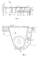
- FIG. 1 is a partly sectional schematic side view of a flotation device according to the invention. It has a flotation basin 1 which, as shown in Figure 2, is downward convergent and roundish at the bottom.
- the flotation basin 1 stands on a suitable platform on feet 2 or a separate body, for instance.
- the sand to be treated and the minerals and other impurities therein are fed into the flotation basin from its first end; in Figure 1, this is the left end indicated by arrow S.
- Foam formed by air and flotation fluid is fed by means of the flotation device from the bottom of the flotation basin 1, and the foam makes the material at the bottom of the flotation basin to move and, at the same time as it rises to the top of the flotation basin, it takes along various unwanted impurities and minerals, such as feldspar, mica, humus, and very fine-grained materials.
- the fluid in the flotation basin which generally is mainly water, contains flotation chemicals that are added as necessary along with the minerals. Flotation chemicals are generally known per se and used in the flotation of minerals.
- the discharge channel 6 At the other end of the flotation basin 1, there is a discharge channel 6 at the bottom of the flotation basin 1.
- the discharge channel 6 may have a control valve 7 that is able to control the size of the discharge channel 6 opening and thus also the discharge rate of the slurry formed by the sand and fluid.
- the control valve 7 may be a simple flange valve or some other simple control element for controlling the size of the discharge channel 6 opening in one way or another as necessary.
- the flotation basin 1 is preferably divided into several consecutive sections, i.e. flotation cells, which limits the fluid flow in the longitudinal direction of the flotation basin and thus enhances the upward rise of the foam and the efficiency of the treatment of the minerals.
- This is implemented in such a manner that the flotation basin 1 has consecutive partitions 1 a that extend from the top edge of the flotation basin 1 or nearly from the top edge to the bottom part of the flotation basin so that essentially only an opening large enough for the conveyor screw 3 remains at the bottom of the partition.
- the end wall of the flotation basin and the partitions 1 a respectively form several consecutive basin sections, i.e. flotation cells.
- There is preferably one foam-forming device 5 for each flotation cell which is normally enough to obtain the desired flotation efficiency.
- it is possible to install several foam-forming devices per one flotation cell, if it is deemed necessary due to the properties of the minerals to be treated, for instance.
- the foam-forming device 5 At the end of the flotation basin, i.e. in the flotation cell connected to the discharge channel 6, the foam-forming device 5 is located close to the previous partition 1 a. As a result of this, the most significant upwards flow is at the forward end of the cell and settling takes place at the tail end of the cell as the sand slowly sinks downward to the bottom of the flotation basin and on to the discharge channel 6. At the same time, the flotation fluid is naturally relatively well cleared of the materials being treated and can thus be returned by suitable means to the forward end of the flotation basin 1 or else- where in the flotation basin 1 to one or more earlier points in the direction of flow of the flotation fluid, i.e. to the foam-forming devices 5, for instance, and then on for reuse.
- each foam-forming device 5 is controlled by a separate control, such as a valve 9, in each foam-forming device.
- FIG. 2 shows the flotation device for minerals cut along line A-A.
- the flotation basin 1 is downward convergent in cross-section and has a roundish bottom so as to suitably match the shape of the conveyor screw 3.
- the flotation device has on one side of the flotation basin 1 a foam discharge chute 10, to which the foam accumulated on the surface of the fluid and the materials bound into the foam run over the side of the flotation basin 1.
- the foam-forming device 5 is a device in a separate box-like channel 11 and has one or more flotation propellers 12 rotated by a motor 13.
- the fluid in the flotation basin 1 exits for instance from the tail end of the flotation basin 1 to a return pipe or chute 8 connected thereto through an opening or over one side and flows along it to each box-like channel 11 in the manner shown schematically by the arrow and controlled by a control 9 shown as a control plate movable in elevation.
- the flotation propellers 12 mix the fluid and air into foam that moves through a gap 14 at the bottom end of the channel 11 on through a second narrow gap 15 to the flotation basin 1 below the conveyor screw 3, whereby the foam takes along the impurities and fine material as it flows through the sand and minerals.
- the foam-forming devices 5 are separate from the flotation basin 1 and thus the flotation propellers 12 of the foam-forming device mainly come into contact with just the fluid and flotation chemicals and air, and are not required to stir the materials being treated, as is typically the case in the prior art solutions. Therefore, the wear of the flotation propellers is in practice quite small and consequently, they require very little servicing.
- the flotation of the fluid i.e. water and chemicals
- air can also be fed from other directions, if the movement of the minerals and impurities is to be improved in the flotation basin.
Landscapes
- Engineering & Computer Science (AREA)
- Life Sciences & Earth Sciences (AREA)
- Biotechnology (AREA)
- Chemical & Material Sciences (AREA)
- Chemical Kinetics & Catalysis (AREA)
- General Engineering & Computer Science (AREA)
- Separation Of Solids By Using Liquids Or Pneumatic Power (AREA)
- Underground Or Underwater Handling Of Building Materials (AREA)
Applications Claiming Priority (2)
| Application Number | Priority Date | Filing Date | Title |
|---|---|---|---|
| FI20030345U | 2003-09-23 | ||
| FI20030345U FI6034U1 (fi) | 2003-09-23 | 2003-09-23 | Vaahdotuslaite mineraalien erottamiseksi hiekasta |
Publications (2)
| Publication Number | Publication Date |
|---|---|
| EP1518606A2 true EP1518606A2 (de) | 2005-03-30 |
| EP1518606A3 EP1518606A3 (de) | 2005-06-01 |
Family
ID=27838804
Family Applications (1)
| Application Number | Title | Priority Date | Filing Date |
|---|---|---|---|
| EP04104550A Withdrawn EP1518606A3 (de) | 2003-09-23 | 2004-09-21 | Flotationsvorrichtung zur Abtrennung der Mineralien vom Sand. |
Country Status (2)
| Country | Link |
|---|---|
| EP (1) | EP1518606A3 (de) |
| FI (1) | FI6034U1 (de) |
Cited By (2)
| Publication number | Priority date | Publication date | Assignee | Title |
|---|---|---|---|---|
| DK178361B1 (en) * | 2013-08-27 | 2016-01-11 | Dennis Søgaard | An apparatus for removing supsended solids from liquids |
| CN109290065A (zh) * | 2018-09-06 | 2019-02-01 | 山西智卓电气有限公司 | 一种浮选尾煤三参数图像检测装置与方法 |
Family Cites Families (6)
| Publication number | Priority date | Publication date | Assignee | Title |
|---|---|---|---|---|
| GB695107A (en) * | 1949-06-15 | 1953-08-05 | Westfalia Dinnendahl Groeppel | Improvements in or relating to froth flotation apparatus |
| DE2832277A1 (de) * | 1978-07-22 | 1980-01-31 | Guenther Abel | Vorrichtung zur behandlung von abwaessern |
| DE4415858A1 (de) * | 1994-05-05 | 1995-11-09 | Bormet Horst | Verfahren und Vorrichtung zur Sedimentabscheidung aus Abwasser |
| DE4418758A1 (de) * | 1994-05-28 | 1995-11-30 | Ecotechniek Bv | Reinigungseinrichtung für Sand, mit Gaseinleitung im unteren Bereich |
| US5562832A (en) * | 1995-01-13 | 1996-10-08 | Beloit Technologies, Inc. | Absorptive sludge dewatering process for papermaking waste |
| DE19850320C2 (de) * | 1998-11-02 | 2002-09-26 | Hans Huber Ag Masch & Anlagenb | Kompaktanlage für die mechanische Reinigung von Abwasser |
-
2003
- 2003-09-23 FI FI20030345U patent/FI6034U1/fi not_active IP Right Cessation
-
2004
- 2004-09-21 EP EP04104550A patent/EP1518606A3/de not_active Withdrawn
Cited By (2)
| Publication number | Priority date | Publication date | Assignee | Title |
|---|---|---|---|---|
| DK178361B1 (en) * | 2013-08-27 | 2016-01-11 | Dennis Søgaard | An apparatus for removing supsended solids from liquids |
| CN109290065A (zh) * | 2018-09-06 | 2019-02-01 | 山西智卓电气有限公司 | 一种浮选尾煤三参数图像检测装置与方法 |
Also Published As
| Publication number | Publication date |
|---|---|
| FIU20030345U0 (fi) | 2003-09-23 |
| EP1518606A3 (de) | 2005-06-01 |
| FI6034U1 (fi) | 2003-11-28 |
Similar Documents
| Publication | Publication Date | Title |
|---|---|---|
| CA1337774C (en) | Flotation machine | |
| CN101511488B (zh) | 用于浮选和分级矿浆的设备和方法 | |
| KR101654508B1 (ko) | 경사판 침전조 겸용 오폐수 가압부상장치 | |
| US4659458A (en) | Apparatus and method for froth flotation employing rotatably mounted spraying and skimming means | |
| US992629A (en) | Apparatus for dewatering and classifying ores. | |
| US2353152A (en) | Method of concentrating minerals | |
| KR102333987B1 (ko) | 이동형 정화 세척침전 장치 | |
| US5169004A (en) | Method of and apparatus for treating building rubble | |
| JPS6233564A (ja) | 汚砂の処理方法およびその装置 | |
| CN109013045B (zh) | 垃圾除砂系统及除砂方法 | |
| US3330413A (en) | Apparatus for biological purification of sewage water | |
| CN207698588U (zh) | 床层厚度可调节的煤矸石破碎原料缓冲预混装置 | |
| RU2174449C1 (ru) | Способ гидравлической классификации мелкофракционных материалов | |
| JPH09299826A (ja) | 骨材に混入した軽質物質を除去する方法及び装置 | |
| RU2106912C1 (ru) | Шлюз для обогащения россыпей | |
| US3043430A (en) | Sand skimmer | |
| US2460801A (en) | Method and means for hindered settling classification | |
| CN207951699U (zh) | 皮带自张紧式煤矸石破碎原料冲洗混合装置 | |
| RU2113906C1 (ru) | Гидравлический концентратор | |
| RU2080935C1 (ru) | Гидравлический концентратор | |
| KR200331910Y1 (ko) | 재생골재의 코팅장치 | |
| CN101203316A (zh) | 用于从液体中分离固体的设备 | |
| JP4832946B2 (ja) | 砂とシルト分の分離方法及び装置 | |
| US3420371A (en) | Heavy medium separator | |
| GB2584489A (en) | A device for treating and recycling water |
Legal Events
| Date | Code | Title | Description |
|---|---|---|---|
| PUAI | Public reference made under article 153(3) epc to a published international application that has entered the european phase |
Free format text: ORIGINAL CODE: 0009012 |
|
| AK | Designated contracting states |
Kind code of ref document: A2 Designated state(s): AT BE BG CH CY CZ DE DK EE ES FI FR GB GR HU IE IT LI LU MC NL PL PT RO SE SI SK TR |
|
| AX | Request for extension of the european patent |
Extension state: AL HR LT LV MK |
|
| PUAL | Search report despatched |
Free format text: ORIGINAL CODE: 0009013 |
|
| AK | Designated contracting states |
Kind code of ref document: A3 Designated state(s): AT BE BG CH CY CZ DE DK EE ES FI FR GB GR HU IE IT LI LU MC NL PL PT RO SE SI SK TR |
|
| AX | Request for extension of the european patent |
Extension state: AL HR LT LV MK |
|
| RIC1 | Information provided on ipc code assigned before grant |
Ipc: 7B 03D 1/22 B Ipc: 7B 01D 21/24 B Ipc: 7B 03D 1/16 A |
|
| 17P | Request for examination filed |
Effective date: 20051114 |
|
| AKX | Designation fees paid |
Designated state(s): AT BE BG CH CY CZ DE DK EE ES FI FR GB GR HU IE IT LI LU MC NL PL PT RO SE SI SK TR |
|
| STAA | Information on the status of an ep patent application or granted ep patent |
Free format text: STATUS: THE APPLICATION IS DEEMED TO BE WITHDRAWN |
|
| 18D | Application deemed to be withdrawn |
Effective date: 20110401 |