EP1518531B1 - Düsenanordnung für Hydromassagebäder - Google Patents
Düsenanordnung für Hydromassagebäder Download PDFInfo
- Publication number
- EP1518531B1 EP1518531B1 EP04077547A EP04077547A EP1518531B1 EP 1518531 B1 EP1518531 B1 EP 1518531B1 EP 04077547 A EP04077547 A EP 04077547A EP 04077547 A EP04077547 A EP 04077547A EP 1518531 B1 EP1518531 B1 EP 1518531B1
- Authority
- EP
- European Patent Office
- Prior art keywords
- valving element
- nozzle
- nozzle assembly
- water
- hole
- Prior art date
- Legal status (The legal status is an assumption and is not a legal conclusion. Google has not performed a legal analysis and makes no representation as to the accuracy of the status listed.)
- Expired - Lifetime
Links
Images



Classifications
-
- A—HUMAN NECESSITIES
- A61—MEDICAL OR VETERINARY SCIENCE; HYGIENE
- A61H—PHYSICAL THERAPY APPARATUS, e.g. DEVICES FOR LOCATING OR STIMULATING REFLEX POINTS IN THE BODY; ARTIFICIAL RESPIRATION; MASSAGE; BATHING DEVICES FOR SPECIAL THERAPEUTIC OR HYGIENIC PURPOSES OR SPECIFIC PARTS OF THE BODY
- A61H33/00—Bathing devices for special therapeutic or hygienic purposes
- A61H33/60—Components specifically designed for the therapeutic baths of groups A61H33/00
- A61H33/601—Inlet to the bath
- A61H33/6021—Nozzles
- A61H33/6063—Specifically adapted for fitting in bathtub walls
-
- A—HUMAN NECESSITIES
- A61—MEDICAL OR VETERINARY SCIENCE; HYGIENE
- A61H—PHYSICAL THERAPY APPARATUS, e.g. DEVICES FOR LOCATING OR STIMULATING REFLEX POINTS IN THE BODY; ARTIFICIAL RESPIRATION; MASSAGE; BATHING DEVICES FOR SPECIAL THERAPEUTIC OR HYGIENIC PURPOSES OR SPECIFIC PARTS OF THE BODY
- A61H33/00—Bathing devices for special therapeutic or hygienic purposes
- A61H33/02—Bathing devices for use with gas-containing liquid, or liquid in which gas is led or generated, e.g. carbon dioxide baths
- A61H33/027—Gas-water mixing nozzles therefor
-
- A—HUMAN NECESSITIES
- A61—MEDICAL OR VETERINARY SCIENCE; HYGIENE
- A61H—PHYSICAL THERAPY APPARATUS, e.g. DEVICES FOR LOCATING OR STIMULATING REFLEX POINTS IN THE BODY; ARTIFICIAL RESPIRATION; MASSAGE; BATHING DEVICES FOR SPECIAL THERAPEUTIC OR HYGIENIC PURPOSES OR SPECIFIC PARTS OF THE BODY
- A61H33/00—Bathing devices for special therapeutic or hygienic purposes
- A61H33/02—Bathing devices for use with gas-containing liquid, or liquid in which gas is led or generated, e.g. carbon dioxide baths
- A61H2033/023—Bathing devices for use with gas-containing liquid, or liquid in which gas is led or generated, e.g. carbon dioxide baths with means in the air supply lines to prevent back-feed of water, e.g. anti-backflow valves, draining devices
-
- A—HUMAN NECESSITIES
- A61—MEDICAL OR VETERINARY SCIENCE; HYGIENE
- A61H—PHYSICAL THERAPY APPARATUS, e.g. DEVICES FOR LOCATING OR STIMULATING REFLEX POINTS IN THE BODY; ARTIFICIAL RESPIRATION; MASSAGE; BATHING DEVICES FOR SPECIAL THERAPEUTIC OR HYGIENIC PURPOSES OR SPECIFIC PARTS OF THE BODY
- A61H33/00—Bathing devices for special therapeutic or hygienic purposes
- A61H33/60—Components specifically designed for the therapeutic baths of groups A61H33/00
- A61H33/601—Inlet to the bath
- A61H33/6021—Nozzles
- A61H33/6052—Having flow regulating means
Definitions
- the present invention relates in general to a nozzle assembly for feeding water into the interior of the tub of a hydromassage bath, and in particular for feeding a mixture of water and air.
- Hydromassage baths are known to comprise a tub provided, on its walls, with nozzle assemblies fed by a system which draws water from the tub after its filling, and feeds it, under pressure, back into the tub via suitably shaped nozzles; either pressurized water alone or a mixture of water and air can be fed.
- the nozzle assemblies do not allow water to pass either into the nozzle assemblies themselves or into the pipes of said system, to prevent stagnation of water which, being mixed with substances removed form the user's skin and scum, could create moulds and bacteria which would be recirculated when effecting hydromassage, and also create blocking problems for the devices inside the nozzle assembly.
- said nozzle assemblies must also draw air from the external environment and mix it into the jet of pressurized water to enable the hydromassage to be effected with a mixture of air and water.
- nozzle assemblies of the above described type are shown in US-A-4 896 384 and EP-A-0 297 246 .
- nozzle assemblies are known presenting unidirectional valves arranged to prevent the water in the bath tub from flowing back into the nozzle interior. Being positioned along the flow direction of the pressurized water, they operate with a relatively high pressure drop as the resistance of the reaction spring of said valves has to be overcome, and moreover they are costly, and bulky to position in the interior of the nozzle assembly.
- An object of the present invention is to overcome the stated drawbacks within the framework of a simple and rational solution.
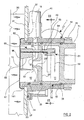
- Figures 1 and 2 show a nozzle assembly 1 to be fixed to a wall 31 of a tub 30 of the bath.
- Said nozzle assembly 1 comprises a casing consisting of a first tubular part 14 to be fixed in correspondence with a respective hole 32 provided in the wall 31 to feed into the tub 30 a respective water jet originating from the nozzle assembly 1, and a second part 16 to be housed as an exact fit within an inner cylindrical surface 15 of said first part 14.
- the casing 14, 16 comprises a first chamber 11, connected to a supply conduit 40 and a discharge conduit 42, and a second chamber 12, directly connected to a suction conduit 41 via a passage 18; said chambers 11 and 12 are separated from each other by a separation wall 21.
- the water supply conduit 40, the discharge conduit 42 and the suction conduit 41 are fixed to said casing 14, 16.
- Said parts 14 and 16 present suitable seats for gaskets 34, 35 and 36, used to prevent air seepage from the second chamber 12 and to prevent water seepage from the first chamber 11.
- the second part 16 presents an outer edge 141 bent rearward to fix it to the wall 31; in this respect, said part 16 is firstly inserted into the hole 32 until the edge 141 is brought into contact with the outer surface of the wall 31 then, after the first part 14 has been fitted onto the second part 16, a clamping nut 70 is screwed onto a thread 71 provided on that portion of the second part 16 distant from the bath tub 30, to lock the first part 14 to the wall 31.
- the first part 14 is sealed against water seepage from the tub 30 by the presence of a suitable annular seat 37 filled with silicone, and a gasket 33.
- the second part 16 is separated from the tub 30 by a cover 17, at the centre of which there is an ejection hole 13.
- the nozzle assembly 1 comprises a nozzle 20, positioned on the separation wall 21 and having a through channel 23 which connects the first chamber 11 to the second chamber 12 and possesses a mouth 22 projecting into the second chamber 12; said nozzle 20 produces a water jet with its exit directed towards the ejection hole 13.
- the nozzle assembly 1 also comprises, in the second chamber 12, a movable valving element 50 to open or vice versa close the ejection hole 13 and suitably operated by operating means 51.
- the valving element 50 is bounded by a front first wall 56 parallel to and adhering or nearly adhering to the ejection hole 13, and a rear second wall 57 opposite the front wall 56 and parallel to and adhering or nearly adhering to the projecting mouth 22 of the nozzle 20 when the valving element 50 moves into its closed position.
- the valving element 50 also comprises a through channel 55 internally disposed between the first wall 56 and the second wall 57 and shaped to enable, in combination with the nozzle 20, air to be drawn in from the second chamber 12 via suitable apertures 19, and to form a mixture of air and water.
- the through channel 55 presents an initial portion disposed in proximity to the nozzle 20, and having a cross-section greater than the cross-section of the channel 23 at the mouth 22; that part of this initial portion which extends radially from the projecting mouth 22 of the nozzle 20 defines said apertures 19.
- the channel 55 presents a cross-section which gradually converges to transform the energy due to the water pressure into kinetic energy to increase the water outflow velocity.
- the final portion of the channel 55 presents a constant cross-section, close to the cross-section of the ejection hole 13.
- Said operating means 51 comprise a blade 52 positioned in the first chamber 11, and rigidly fixed to a first portion of a rod 53, which is rotatably inserted through a hole 25 provided in the separation wall 21, and of which the second portion is rigidly fixed to the valving element 50.
- the rod 53 defines the axis of rotation of the valving element 50 which is perpendicular (or a small angle off perpendicular) to the plane of the ejection hole 13; as will be apparent hereinafter, this axis is positioned at a suitable distance from the barycentre of the valving element 50.
- the blade 52 is shaped with a profile presenting a concave surface to the water from the supply conduit 40, to increase the thrust of the water on the blade 52.
- the nozzle assembly 1 is connected to a further nozzle assembly, positioned downstream, by means of the discharge conduit 42, which is connected to the supply conduit 40 of said further nozzle assembly, said nozzle assembly 1 being connected to a preceding upstream nozzle assembly by means of its supply conduit 40, which is connected to the discharge conduit of said preceding nozzle assembly.
- a pump of the hydraulic system connected to the nozzle assemblies withdraws water from the tub 30 of the bath and feeds it under pressure to the supply conduit 40.
- the pressurized water enters the first chamber 11 to strike against the surface of the blade 52, to generate about the axis of the rod 53 a first twisting movement able to position the valving element 50 in a first open position.
- Said open position (see Figure 3 and Figure 4B ) is such that the channel 55 becomes positioned coaxial to the nozzle 20, through which the pressurized water jet originates, and to the ejection hole 13, to enable a mixture of air and water to be ejected towards the tub 30 of the bath.
- said valving element 50 moves into the closed position, with its front wall 56 adhering to the ejection hole 13 to close it, and with its rear wall 57 adhering to and closing the projecting mouth 22 of the nozzle 20 (see Figure 4A ); by virtue of this, the water present in the tub is prevented from penetrating into the second chamber 12, or at least any organic substances are prevented from being able to flow back into the second chamber and from there to the first chamber 11, creating moulds and bacteria and possible blockage.
- Said closed position is achieved because of the fact that as the barycentre of the valving element 50 is displaced from its axis of rotation (axis of the rod 53), the weight of the valving element 50 creates a second twisting moment about the axis of the rod 53, to return the valving element 50 into its normal closed position, where it adheres to the cover 17 and to the nozzle 20.
- Elastic means in particular a torsion spring 54, can be added to return the valving element 50 into its closed position when water flow is lacking.
- this either has a totally or partly ferromagnetic body, or presents two counter-magnets 26a and 27a having opposite polarities to the corresponding magnets 26 and respectively 27 and positioned on opposite sides of the valving element 50; the magnets and counter-magnets are in geometrical relationship to each other such that when the valving element is in its closed position ( Figure 4A ), the magnet 26 is in contact or near contact with the counter-magnet 26a, whereas when the valving element is in its open position ( Figure 4B ), the second magnet 27 is in contact or near contact with the counter-magnet 27a.
- pairs of magnets and counter-magnets 26-26a and 27-27a serve to secure the valving element with a certain force, maintaining it in either its closed or open position.
- the force of the pressurized water which on entering the first chamber 11 strikes the blade 52 is able to overcome the force of attraction between the magnet 26 and counter-magnet 26a, whereas the thrust of the spring 54 and the weight of the valving element 50 is able to overcome the force of attraction between the magnet 27 and counter-magnet 27a when the thrust of the pressurized water against the blade 52 ceases.
- the rod 53 possesses a threaded intermediate portion which is helically engaged with the likewise threaded hole 25 in the wall 21; this engagement is such that when the valving element 50 is in its open position (as shown by the full lines in Figure 2A ), it lies at a distance (a few millimetres) from the hole 13; in contrast, when the valving element 50 rotates into its closed position (as shown by dashed lines in Figure 2A ), the engagement with the hole 25 causes it not only to rotate but also to translate, at least a little, towards the hole 13, until its front wall 56 adheres to it. Effective adhesion of the valving element against the hole 13 can hence be obtained, with consequent effective closure thereof.
Landscapes
- Health & Medical Sciences (AREA)
- Public Health (AREA)
- Life Sciences & Earth Sciences (AREA)
- Pain & Pain Management (AREA)
- Physical Education & Sports Medicine (AREA)
- Rehabilitation Therapy (AREA)
- Epidemiology (AREA)
- Animal Behavior & Ethology (AREA)
- General Health & Medical Sciences (AREA)
- Veterinary Medicine (AREA)
- Nozzles (AREA)
- Electroplating Methods And Accessories (AREA)
- Preparing Plates And Mask In Photomechanical Process (AREA)
- Percussion Or Vibration Massage (AREA)
- Devices For Medical Bathing And Washing (AREA)
Claims (12)
- Eine Düsenanordnung (1) für Hydromassagebäder zum Anbringen an eine Wand (31) der Badewanne (30), einschließlich der folgenden Elemente:- Eines Gehäuses (14, 16) zum Anbringen an eine Wand (31) der Badewanne (30) in Entsprechung zu einer Öffnung (32) für den Wasserzulauf in die Wanne (30) und selbst ausgestattet mit einer Öffnung (13) zum Ausstoßen des Wasserstrahls in die Wanne (30) mit wenigstens einer mit dem Gehäuse (14, 16) verbundenen Wasserzuleitung (40);- Einer Düse (20), die so angeordnet ist, dass sie einen auf die Ausstoßöffnung (13) gerichteten Wasserstrahl produziert, wobei das unter Druck stehende Wasser aus der Zuleitung (40) kommt und durch die Düse (20) und die Ausstoßöffnung (13) ausgestoßen wird;- Einer bewegbaren Verteileinrichtung (50), die zum Öffnen oder Verschließen der Ausstoßöffnung (13) quer zur Achse der Düse (20) bewegt werden kann;Dadurch gekennzeichnet, dass:- Die Verteileinrichtung (50) so angeordnet ist, dass sie auf einer Drehachse senkrecht zur Ebene der Ausstoßöffnung (13) drehbar ist;- Die Anordnung Betriebsvorrichtungen (51) beinhaltet, welche dem Druck des Wassers aus der Zuleitung (40) ausgesetzt werden und die Verteileinrichtung (50) zum Drehen in die geöffnete Position bringen, wenn ein Wasserstrahl in einer ersten Kammer (11) ankommt und umgekehrt die Verteileinrichtung (50) in die geschlossene Position zurückbringen, wenn der Wasserstrahl ausbleibt.
- Eine Düsenanordnung nach Patentanspruch 1, dadurch gekennzeichnet, dass:- Das Gehäuse eine erste Kammer (11) und eine zweite Kammer (12) besitzt, die voneinander getrennt sind;- Sich die Ausstoßöffnung (13) in der zweiten Kammer (12) befindet;- Sich die Düse (20) an der Trennwand (21) zwischen den beiden Kammern (11, 12) befindet;- Sich die Verteileinrichtung (50) in der zweiten Kammer (12) befindet.
- Eine Düsenanordnung nach Patentanspruch 2, dadurch gekennzeichnet, dass die Verteileinrichtung (50) eine erste vordere Wand (56) enthält, die parallel zur Ebene der Ausstoßöffnung (13) liegt und an der Ausstoßöffnung (13) anliegt, wenn sich die Verteileinrichtung (50) in geschlossener Position befindet.
- Eine Düsenanordnung nach Patentanspruch 1, dadurch gekennzeichnet, dass die Verteileinrichtung (50) eine zweite hintere Wand (57) enthält, die parallel zur Ebene einer Mündung (22) der Düse (20) liegt und an diese Mündung (22) anliegt, wenn sich die Verteileinrichtung (50) in geschlossener Position befindet.
- Eine Düsenanordnung nach Patentanspruch 1, dadurch gekennzeichnet, dass die Betriebsvorrichtungen (51) eine Schaufel (52) beinhalten, die sich in der ersten Kammer (11) befindet und die fest an einen Stab (53) angebracht ist, welcher wiederum fest mit der Verteileinrichtung (50) verbunden ist und diese dazu bringt, in die offene Position zu drehen, sobald der Wasserdruck auf die Oberfläche der Schaufel (52) einwirkt und die Verteileinrichtung (50) umgekehrt zurück in die geschlossene Position verbringt, sobald der Wasserstrahl ausbleibt.
- Eine Düsenanordnung nach Patentanspruch 1, dadurch gekennzeichnet, dass die Drehachse der Verteileinrichtung (50) von deren Schwerpunkt entfernt ist, wobei dieser Abstand ein Zurückfallen der Verteileinrichtung (50) in die geschlossene Position aufgrund des Gewichts derselben ermöglicht.
- Eine Düsenanordnung nach Patentanspruch 5, dadurch gekennzeichnet, dass die Schaufel (52) elastische Vorrichtungen (54) beinhaltet, die so angeordnet sind, dass sie die Verteileinrichtung (50) in eine anfängliche Ruheposition verbringen, die mit der geschlossenen Position übereinstimmt.
- Eine Düsenanordnung nach Patentanspruch 5, dadurch gekennzeichnet, dass der Stab (53) spiralförmig mit einer Öffnung (25) derart verbunden ist, dass sich die Verteileinrichtung (50) zusätzlich zur Drehung in die geschlossene Position auch in Richtung zur Ausstoßöffnung (13) hin bewegt, so dass sie in der geschlossenen Position mit der vorderen Wand an diese anschließt.
- Eine Düsenanordnung nach Patentanspruch 5, dadurch gekennzeichnet, dass auf einer Innenseite eines zweiten Bauelements (16) des Gehäuses (14, 16) ein erster Magnet (26) und auf der gegenüberliegenden Innenseite ein zweiter Magnet (27) angebracht sind, die beide dazu in der Lage sind, die Verteileinrichtung (50) durch magnetische Anziehungskraft in der geschlossenen oder umgekehrt in der offenen Position zu sichern.
- Eine Düsenanordnung nach Patentanspruch 2, dadurch gekennzeichnet, dass die zweite Kammer (12) mit wenigstens einer Luftansaugleitung (41) verbunden ist.
- Eine Düsenanordnung nach Patentanspruch 10, dadurch gekennzeichnet, dass die Verteileinrichtung (50) einen Durchgangskanal (55) beinhaltet, der so geschnitten ist, dass er in Zusammenarbeit mit der Düse (20) Luft zur Bildung einer aus der Düse (20) stammenden Luft-Wasser-Mischung ansaugt, wobei der Kanal (55) bei offener Position der Verteileinrichtung (50) koaxial zur Düse (20) und zur Ausstoßöffnung (13) ist.
- Eine Düsenanordnung nach Patentanspruch 1, dadurch gekennzeichnet, dass das Gehäuse (14, 16) folgende Elemente beinhaltet:- Ein erstes Bauelement (14), das durch die Öffnung (32) an die Wand (31) angebracht wird;- Ein zweites Bauelement (16), in dessen Inneren sich die Kammern (11, 12) befinden, und welches genau die Maße der Innenfläche (15) des ersten Bauelements (14) hat, um innerhalb desselben untergebracht zu werden;- Eine Klemmmutter (70) und ein Gewinde (71) auf einem von der Badewanne (30) entfernten Abschnitt des zweiten Bauelements (16), um das zweite Bauelement (16) axial am ersten Bauelement (14) zu fixieren.
Applications Claiming Priority (2)
| Application Number | Priority Date | Filing Date | Title |
|---|---|---|---|
| ITRE20030091 | 2003-09-29 | ||
| IT000091A ITRE20030091A1 (it) | 2003-09-29 | 2003-09-29 | Bocchetta per vasche da idromassaggio. |
Publications (2)
| Publication Number | Publication Date |
|---|---|
| EP1518531A1 EP1518531A1 (de) | 2005-03-30 |
| EP1518531B1 true EP1518531B1 (de) | 2008-08-13 |
Family
ID=34179347
Family Applications (1)
| Application Number | Title | Priority Date | Filing Date |
|---|---|---|---|
| EP04077547A Expired - Lifetime EP1518531B1 (de) | 2003-09-29 | 2004-09-15 | Düsenanordnung für Hydromassagebäder |
Country Status (4)
| Country | Link |
|---|---|
| EP (1) | EP1518531B1 (de) |
| AT (1) | ATE404151T1 (de) |
| DE (1) | DE602004015692D1 (de) |
| IT (1) | ITRE20030091A1 (de) |
Families Citing this family (1)
| Publication number | Priority date | Publication date | Assignee | Title |
|---|---|---|---|---|
| ITRE20040055A1 (it) * | 2004-05-19 | 2004-08-19 | American Standard Europe Bvba | Bocchetta per vasche da idromassaggi |
Family Cites Families (5)
| Publication number | Priority date | Publication date | Assignee | Title |
|---|---|---|---|---|
| IT1200742B (it) * | 1985-09-17 | 1989-01-27 | Teuco Guzzini Srl | Vasca da bagno con impianto per idromassagio perfezionato |
| DE8631764U1 (de) * | 1986-11-27 | 1987-06-25 | Ucosan B.V., Roden | Austrittsdüse für das Austrittsventil einer Whirlpool-Wanne |
| DE3745024C2 (de) * | 1987-05-06 | 1995-01-19 | Guenter Schuessler | Wasserbecken mit Luftsprudelvorrichtung |
| IT1242208B (it) * | 1990-04-23 | 1994-03-02 | Jacuzzi Europ | Bocchetta per idromassaggio perfezionata |
| IT1274336B (it) * | 1994-03-04 | 1997-07-17 | Jacuzzi Europ | Bocchetta per idromassaggio, particolarmente anche se non esclusivamente per vasca da bagno |
-
2003
- 2003-09-29 IT IT000091A patent/ITRE20030091A1/it unknown
-
2004
- 2004-09-15 DE DE602004015692T patent/DE602004015692D1/de not_active Expired - Lifetime
- 2004-09-15 AT AT04077547T patent/ATE404151T1/de not_active IP Right Cessation
- 2004-09-15 EP EP04077547A patent/EP1518531B1/de not_active Expired - Lifetime
Also Published As
| Publication number | Publication date |
|---|---|
| DE602004015692D1 (de) | 2008-09-25 |
| ATE404151T1 (de) | 2008-08-15 |
| ITRE20030091A1 (it) | 2005-03-30 |
| EP1518531A1 (de) | 2005-03-30 |
Similar Documents
| Publication | Publication Date | Title |
|---|---|---|
| EP1716930B1 (de) | Austragvorrichtung mit einer Vielzahl von Funktionen | |
| US11879243B2 (en) | Bidet washing apparatus with disinfectant wash feature | |
| US12378756B2 (en) | Bidet washing apparatus with disinfectant wash feature | |
| EP3040487B2 (de) | Düsenanordnung für ein bidet | |
| CN106522326B (zh) | 一种防虹吸阀及防虹吸马桶 | |
| WO2016126744A1 (en) | Improved dedicated siphon jet toilet and enhanced vacuum flush system for the same | |
| GB2609055A (en) | Liquid chemical sprayer | |
| AU2009229579B2 (en) | Method for system for a water jet propulsion system for a ship | |
| EP1518531A1 (de) | Düsenanordnung für Hydromassagebäder | |
| CN205701133U (zh) | 一种止水除垢机构及装设有止水除垢机构的花洒 | |
| CN102829237B (zh) | 自动节水龙头 | |
| CA1288302C (en) | Hydrotherapy massage method and apparatus | |
| EP0297246B1 (de) | Wasserbecken mit Luftsprudelvorrichtung, mit verschliessbaren Einstrahldüsen und zirkulierbaren Zuleitungen | |
| CN210357618U (zh) | 一种能自清洁的出水嘴和具有其的喷水装置 | |
| EP1750643B1 (de) | Düse für hydromassagebäder | |
| CN107905314B (zh) | 一种进排水同步的冲刷系统 | |
| CN216616108U (zh) | 一种阀门和采用该阀门的马桶 | |
| CN1323212C (zh) | 可防止回流的坐浴装置 | |
| CN205399613U (zh) | 一种温水便座喷水管组件 | |
| JP4934404B2 (ja) | 衛生洗浄装置付き可搬型便器 | |
| CA2037024C (en) | Water-jet injection device for dispensers | |
| CN222678392U (zh) | 自动封水的喷头结构 | |
| CN222000327U (zh) | 一种喷嘴及洗杯器 | |
| EP2554271B1 (de) | Nicht tropfender brausekopf | |
| JP2006015239A (ja) | 混気ジェット式流送具および混気ジェット機構に設けられる逆止弁 |
Legal Events
| Date | Code | Title | Description |
|---|---|---|---|
| PUAI | Public reference made under article 153(3) epc to a published international application that has entered the european phase |
Free format text: ORIGINAL CODE: 0009012 |
|
| AK | Designated contracting states |
Kind code of ref document: A1 Designated state(s): AT BE BG CH CY CZ DE DK EE ES FI FR GB GR HU IE IT LI LU MC NL PL PT RO SE SI SK TR |
|
| AX | Request for extension of the european patent |
Extension state: AL HR LT LV MK |
|
| 17P | Request for examination filed |
Effective date: 20050804 |
|
| AKX | Designation fees paid |
Designated state(s): AT BE BG CH CY CZ DE DK EE ES FI FR GB GR HU IE IT LI LU MC NL PL PT RO SE SI SK TR |
|
| GRAP | Despatch of communication of intention to grant a patent |
Free format text: ORIGINAL CODE: EPIDOSNIGR1 |
|
| RAP1 | Party data changed (applicant data changed or rights of an application transferred) |
Owner name: IDEAL STANDARD INTERNATIONAL BVBA |
|
| GRAS | Grant fee paid |
Free format text: ORIGINAL CODE: EPIDOSNIGR3 |
|
| GRAA | (expected) grant |
Free format text: ORIGINAL CODE: 0009210 |
|
| AK | Designated contracting states |
Kind code of ref document: B1 Designated state(s): AT BE BG CH CY CZ DE DK EE ES FI FR GB GR HU IE IT LI LU MC NL PL PT RO SE SI SK TR |
|
| REG | Reference to a national code |
Ref country code: GB Ref legal event code: FG4D |
|
| REG | Reference to a national code |
Ref country code: CH Ref legal event code: EP |
|
| REG | Reference to a national code |
Ref country code: IE Ref legal event code: FG4D |
|
| REF | Corresponds to: |
Ref document number: 602004015692 Country of ref document: DE Date of ref document: 20080925 Kind code of ref document: P |
|
| PG25 | Lapsed in a contracting state [announced via postgrant information from national office to epo] |
Ref country code: NL Free format text: LAPSE BECAUSE OF FAILURE TO SUBMIT A TRANSLATION OF THE DESCRIPTION OR TO PAY THE FEE WITHIN THE PRESCRIBED TIME-LIMIT Effective date: 20080813 Ref country code: ES Free format text: LAPSE BECAUSE OF FAILURE TO SUBMIT A TRANSLATION OF THE DESCRIPTION OR TO PAY THE FEE WITHIN THE PRESCRIBED TIME-LIMIT Effective date: 20081124 |
|
| PG25 | Lapsed in a contracting state [announced via postgrant information from national office to epo] |
Ref country code: FI Free format text: LAPSE BECAUSE OF FAILURE TO SUBMIT A TRANSLATION OF THE DESCRIPTION OR TO PAY THE FEE WITHIN THE PRESCRIBED TIME-LIMIT Effective date: 20080813 Ref country code: AT Free format text: LAPSE BECAUSE OF FAILURE TO SUBMIT A TRANSLATION OF THE DESCRIPTION OR TO PAY THE FEE WITHIN THE PRESCRIBED TIME-LIMIT Effective date: 20080813 Ref country code: SI Free format text: LAPSE BECAUSE OF FAILURE TO SUBMIT A TRANSLATION OF THE DESCRIPTION OR TO PAY THE FEE WITHIN THE PRESCRIBED TIME-LIMIT Effective date: 20080813 |
|
| PG25 | Lapsed in a contracting state [announced via postgrant information from national office to epo] |
Ref country code: BE Free format text: LAPSE BECAUSE OF FAILURE TO SUBMIT A TRANSLATION OF THE DESCRIPTION OR TO PAY THE FEE WITHIN THE PRESCRIBED TIME-LIMIT Effective date: 20080813 |
|
| PG25 | Lapsed in a contracting state [announced via postgrant information from national office to epo] |
Ref country code: DK Free format text: LAPSE BECAUSE OF FAILURE TO SUBMIT A TRANSLATION OF THE DESCRIPTION OR TO PAY THE FEE WITHIN THE PRESCRIBED TIME-LIMIT Effective date: 20080813 Ref country code: BG Free format text: LAPSE BECAUSE OF FAILURE TO SUBMIT A TRANSLATION OF THE DESCRIPTION OR TO PAY THE FEE WITHIN THE PRESCRIBED TIME-LIMIT Effective date: 20081113 Ref country code: MC Free format text: LAPSE BECAUSE OF NON-PAYMENT OF DUE FEES Effective date: 20080930 |
|
| REG | Reference to a national code |
Ref country code: CH Ref legal event code: PL |
|
| PG25 | Lapsed in a contracting state [announced via postgrant information from national office to epo] |
Ref country code: RO Free format text: LAPSE BECAUSE OF FAILURE TO SUBMIT A TRANSLATION OF THE DESCRIPTION OR TO PAY THE FEE WITHIN THE PRESCRIBED TIME-LIMIT Effective date: 20080813 Ref country code: PT Free format text: LAPSE BECAUSE OF FAILURE TO SUBMIT A TRANSLATION OF THE DESCRIPTION OR TO PAY THE FEE WITHIN THE PRESCRIBED TIME-LIMIT Effective date: 20090113 Ref country code: CZ Free format text: LAPSE BECAUSE OF FAILURE TO SUBMIT A TRANSLATION OF THE DESCRIPTION OR TO PAY THE FEE WITHIN THE PRESCRIBED TIME-LIMIT Effective date: 20080813 Ref country code: SK Free format text: LAPSE BECAUSE OF FAILURE TO SUBMIT A TRANSLATION OF THE DESCRIPTION OR TO PAY THE FEE WITHIN THE PRESCRIBED TIME-LIMIT Effective date: 20080813 |
|
| PLBE | No opposition filed within time limit |
Free format text: ORIGINAL CODE: 0009261 |
|
| STAA | Information on the status of an ep patent application or granted ep patent |
Free format text: STATUS: NO OPPOSITION FILED WITHIN TIME LIMIT |
|
| 26N | No opposition filed |
Effective date: 20090514 |
|
| PG25 | Lapsed in a contracting state [announced via postgrant information from national office to epo] |
Ref country code: IE Free format text: LAPSE BECAUSE OF NON-PAYMENT OF DUE FEES Effective date: 20080915 Ref country code: EE Free format text: LAPSE BECAUSE OF FAILURE TO SUBMIT A TRANSLATION OF THE DESCRIPTION OR TO PAY THE FEE WITHIN THE PRESCRIBED TIME-LIMIT Effective date: 20080813 |
|
| PG25 | Lapsed in a contracting state [announced via postgrant information from national office to epo] |
Ref country code: CH Free format text: LAPSE BECAUSE OF NON-PAYMENT OF DUE FEES Effective date: 20080930 Ref country code: LI Free format text: LAPSE BECAUSE OF NON-PAYMENT OF DUE FEES Effective date: 20080930 |
|
| PG25 | Lapsed in a contracting state [announced via postgrant information from national office to epo] |
Ref country code: SE Free format text: LAPSE BECAUSE OF FAILURE TO SUBMIT A TRANSLATION OF THE DESCRIPTION OR TO PAY THE FEE WITHIN THE PRESCRIBED TIME-LIMIT Effective date: 20081113 |
|
| PG25 | Lapsed in a contracting state [announced via postgrant information from national office to epo] |
Ref country code: PL Free format text: LAPSE BECAUSE OF FAILURE TO SUBMIT A TRANSLATION OF THE DESCRIPTION OR TO PAY THE FEE WITHIN THE PRESCRIBED TIME-LIMIT Effective date: 20080813 |
|
| PG25 | Lapsed in a contracting state [announced via postgrant information from national office to epo] |
Ref country code: CY Free format text: LAPSE BECAUSE OF FAILURE TO SUBMIT A TRANSLATION OF THE DESCRIPTION OR TO PAY THE FEE WITHIN THE PRESCRIBED TIME-LIMIT Effective date: 20080813 Ref country code: LU Free format text: LAPSE BECAUSE OF NON-PAYMENT OF DUE FEES Effective date: 20080915 Ref country code: HU Free format text: LAPSE BECAUSE OF FAILURE TO SUBMIT A TRANSLATION OF THE DESCRIPTION OR TO PAY THE FEE WITHIN THE PRESCRIBED TIME-LIMIT Effective date: 20090214 |
|
| PG25 | Lapsed in a contracting state [announced via postgrant information from national office to epo] |
Ref country code: TR Free format text: LAPSE BECAUSE OF FAILURE TO SUBMIT A TRANSLATION OF THE DESCRIPTION OR TO PAY THE FEE WITHIN THE PRESCRIBED TIME-LIMIT Effective date: 20080813 |
|
| PG25 | Lapsed in a contracting state [announced via postgrant information from national office to epo] |
Ref country code: GR Free format text: LAPSE BECAUSE OF FAILURE TO SUBMIT A TRANSLATION OF THE DESCRIPTION OR TO PAY THE FEE WITHIN THE PRESCRIBED TIME-LIMIT Effective date: 20081114 |
|
| REG | Reference to a national code |
Ref country code: DE Ref legal event code: R082 Ref document number: 602004015692 Country of ref document: DE Representative=s name: PATENTANWAELTE BECKER & MUELLER, DE |
|
| REG | Reference to a national code |
Ref country code: FR Ref legal event code: PLFP Year of fee payment: 13 |
|
| REG | Reference to a national code |
Ref country code: DE Ref legal event code: R081 Ref document number: 602004015692 Country of ref document: DE Owner name: IDEAL STANDARD INTERNATIONAL NV, BE Free format text: FORMER OWNER: IDEAL-STANDARD INTERNATIONAL BVBA, BRUESSEL, BE Ref country code: DE Ref legal event code: R082 Ref document number: 602004015692 Country of ref document: DE Representative=s name: PATENTANWAELTE BECKER & MUELLER, DE |
|
| REG | Reference to a national code |
Ref country code: FR Ref legal event code: PLFP Year of fee payment: 14 |
|
| REG | Reference to a national code |
Ref country code: FR Ref legal event code: PLFP Year of fee payment: 15 |
|
| PGFP | Annual fee paid to national office [announced via postgrant information from national office to epo] |
Ref country code: IT Payment date: 20230921 Year of fee payment: 20 Ref country code: GB Payment date: 20230927 Year of fee payment: 20 |
|
| PGFP | Annual fee paid to national office [announced via postgrant information from national office to epo] |
Ref country code: FR Payment date: 20230925 Year of fee payment: 20 Ref country code: DE Payment date: 20230927 Year of fee payment: 20 |
|
| REG | Reference to a national code |
Ref country code: DE Ref legal event code: R071 Ref document number: 602004015692 Country of ref document: DE |
|
| REG | Reference to a national code |
Ref country code: GB Ref legal event code: PE20 Expiry date: 20240914 |
|
| PG25 | Lapsed in a contracting state [announced via postgrant information from national office to epo] |
Ref country code: GB Free format text: LAPSE BECAUSE OF EXPIRATION OF PROTECTION Effective date: 20240914 |
|
| PG25 | Lapsed in a contracting state [announced via postgrant information from national office to epo] |
Ref country code: GB Free format text: LAPSE BECAUSE OF EXPIRATION OF PROTECTION Effective date: 20240914 |