EP1518487A1 - Meal tray being divisible in two areas - Google Patents
Meal tray being divisible in two areas Download PDFInfo
- Publication number
- EP1518487A1 EP1518487A1 EP03292385A EP03292385A EP1518487A1 EP 1518487 A1 EP1518487 A1 EP 1518487A1 EP 03292385 A EP03292385 A EP 03292385A EP 03292385 A EP03292385 A EP 03292385A EP 1518487 A1 EP1518487 A1 EP 1518487A1
- Authority
- EP
- European Patent Office
- Prior art keywords
- tray
- strip
- wall
- meal
- plate
- Prior art date
- Legal status (The legal status is an assumption and is not a legal conclusion. Google has not performed a legal analysis and makes no representation as to the accuracy of the status listed.)
- Ceased
Links
Images

Classifications
-
- A—HUMAN NECESSITIES
- A47—FURNITURE; DOMESTIC ARTICLES OR APPLIANCES; COFFEE MILLS; SPICE MILLS; SUCTION CLEANERS IN GENERAL
- A47J—KITCHEN EQUIPMENT; COFFEE MILLS; SPICE MILLS; APPARATUS FOR MAKING BEVERAGES
- A47J39/00—Heat-insulated warming chambers; Cupboards with heating arrangements for warming kitchen utensils
- A47J39/006—Heat-insulated warming chambers; Cupboards with heating arrangements for warming kitchen utensils for either storing and preparing or for preparing food on serving trays, e.g. heating, thawing, preserving
Definitions
- the present invention relates to a meal tray having particular vocation to be applied in storage trolleys of such trays, which are then distributed individually in the school rooms for example type hospitals.
- trolleys are in fact a rolling container composed in part internally two compartments separated by a central wall acting as a barrier thermal, because one of the compartments is kept at a low temperature that the other is heated.
- the food allocated to a patient is arranged on a single tray. Foods intended to be reheated are then grouped on one side, while those that need to be kept low temperature are placed on the other side. The central part of the plateau is then inserted into a horizontal slot in the partition wall between compartments cold and hot, so that each dish is found in the thermally appropriate zone, and that it may be distributed consumption temperature.
- the central wall acts as a thermal barrier and should in principle to avoid inadvertent thermal transfer between the compartments, if only to preserve the food quality taste.
- the cold compartment is thus maintained at a temperature between 0 and 4 ° C, while the hot compartment must keep a temperature between 85 and 140 ° C.
- very strict health standards which set minimum temperature thresholds on the warm side, and maximum side cold, in order to guarantee the food safety of the proposed foods. According to these standards, hygiene is ensured when the temperature at the heart of food is It rises to 63 ° C on the warm side, whereas it is only 8 ° C on the cold side.
- the cart is filled with a stack of trays arranged on side racks, and whose central portion is inserted into said slots. placed at regular intervals over the entire height of the partition wall.
- the existence of these slots poses a problem in this type of carriage, since they obviously favor thermal transfers between compartments while sanitary standards prohibit them and they go to against taste requirements.
- the only direction of travel allowed allows the insertion / extraction of the tray in / of the slot, according to a movement of pace parallel to the axis of the slot. It is not possible to initiate a trip perpendicular, for example to adjust laterally the plateau in the trolley, or to adjust the area allocated respectively to the compartment hot and cold.
- the invention relates to a meal tray having a surface of subdivision into at least two differentiated zones, said plateau having in its central part a substantially flat area intended for to support a thermal sealing wall, the planar area being configured to allow a right or left lateral positioning of the plate with respect to the sealing wall, and relatively adjust the surfaces of both zones differentiated by maintaining the thermal seal.
- the substantially flat area consists of a strip developing transversely to the plateau.
- the ends of said band may comprise grooves oriented substantially perpendicular to the axis of said band, recessed in the thickness of said strip, ie from the bottom of the tray.
- the plate may comprise a raised peripheral edge that also prevents overflow.
- the substantially flat transverse strip of the invention may in fact be applied to many types of trays. So, according to one possibility additional, these trays may comprise, on both sides of the said central band, at least one cell for storing dishes or dishes proposed.
- the trays of the invention although in most cases of shape substantially rectangular, can also take other configurations such as: oval, provided with a transverse wall, provided, however, that satisfies the condition of substantially flat central zone allowing a lateral travel of the plateau, etc.
- each plate (1) is, in this example particular, consisting of a flat bottom (2) whose periphery is coated with a raised border (3). However, the latter does not cover the whole of the periphery since it stops in two places (4,5) located opposite. These mark the ends of the planar-looking central zone which characterizes the invention, forming a transverse band crossing the entire plateau and limited by two fictitious lines (6) and (7) joining the shoulders marking the breaking of the border (3).
- This plane-like band allows plate displacements in a direction substantially perpendicular to the sealing walls, as will emerge more clearly from the rest of the description.
- the plate also has grooves (8) and (9), arranged generally perpendicular to said lines (6, 7), vicinity of openings (4,5), provided to prevent overflow any liquid substances escaping from the dishes placed on the tray.
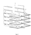
- FIG. 2 shows a wall (P), for example separating the compartments hot and cold carriage, provided with slots (10) at the bottom recesses (11), in which wall guillotines (12) are arranged sealing in the sense of the present invention.
- guillotines (12) are in the rest position in contact with the underside recesses s (11), that is to say in the closed position of the slots (10).
- These guillotines (12), which are contained in their entirety in the recesses (11) made in the wall (P), can of course be moved upwards, in order to unclog the slots (10) in particular for the purpose of inserting trays.
- the trays (1) appear centered with respect to the wall (P).
- This centering thanks to the invention, is not necessary since the existence of the flat central band limited by the shoulders marking the birth of the borders (3) allows on the contrary a deflection in the direction of the arrow F.
- This displacement is limited by the stops precisely constituted by said shoulders. It allows the user to choose, in the limit of the volume offered by the carriage, the plateau area to be affected, for example to the cold compartment, and therefore the one that will be located in the warm compartment.
- the transverse band is centered, and it is of relatively limited width, allowing a displacement itself limited. It is clear, however, that these characteristics are modifiable, and that example, said band can be of much greater width, shifted towards the right, etc. without changing the spirit of the invention.
Landscapes
- Engineering & Computer Science (AREA)
- Food Science & Technology (AREA)
- Packages (AREA)
Abstract
Description
La présente invention concerne un plateau repas ayant notamment vocation à s'appliquer dans des chariots roulants de stockage de tels plateaux, lesquels sont ensuite distribués individuellement dans les chambres d'établissements par exemple de type hôpitaux.The present invention relates to a meal tray having particular vocation to be applied in storage trolleys of such trays, which are then distributed individually in the school rooms for example type hospitals.
Ces chariots constituent en fait un container roulant composé en partie interne de deux compartiments séparés par une paroi centrale faisant office de barrière thermique, car l'un des compartiments est maintenu à basse température alors que l'autre est chauffé.These trolleys are in fact a rolling container composed in part internally two compartments separated by a central wall acting as a barrier thermal, because one of the compartments is kept at a low temperature that the other is heated.
Dans la plupart des cas, la nourriture attribuée à un patient est disposée sur un unique plateau. Les aliments destinés à être réchauffés y sont alors regroupés sur un côté, alors que ceux qui doivent être maintenus à basse température sont placés sur l'autre côté. La partie centrale du plateau est ensuite insérée dans une fente horizontale pratiquée dans la paroi de séparation entre les compartiments froid et chaud, de façon à ce que chaque mets se retrouve dans la zone thermiquement appropriée, et qu'il puisse être distribué à température de consommation.In most cases, the food allocated to a patient is arranged on a single tray. Foods intended to be reheated are then grouped on one side, while those that need to be kept low temperature are placed on the other side. The central part of the plateau is then inserted into a horizontal slot in the partition wall between compartments cold and hot, so that each dish is found in the thermally appropriate zone, and that it may be distributed consumption temperature.
La paroi centrale fait donc office de barrière thermique et doit en principe permettre d'éviter tout transfert thermique intempestif entre les compartiments, ne serait-ce que pour conserver aux aliments leur qualité gustative. The central wall acts as a thermal barrier and should in principle to avoid inadvertent thermal transfer between the compartments, if only to preserve the food quality taste.
Le compartiment froid est ainsi maintenu à une température comprise entre 0 et 4° C, alors que le compartiment chaud doit garder une température comprise entre 85 et 140° C. Outre l'aspect purement gustatif mentionné, le maintien de ces températures est imposé par des normes sanitaires très strictes qui fixent des seuils de température minimale côté chaud, et maximale côté froid, afin de garantir la sécurité alimentaire des denrées proposées. Selon ces normes, l'hygiéne est assurée lorsque la température à coeur des aliments se monte à 63° C côté chaud, alors qu'elle n'est que de 8° C côté froid.The cold compartment is thus maintained at a temperature between 0 and 4 ° C, while the hot compartment must keep a temperature between 85 and 140 ° C. In addition to the purely gustatory aspect maintaining these temperatures is imposed by very strict health standards which set minimum temperature thresholds on the warm side, and maximum side cold, in order to guarantee the food safety of the proposed foods. According to these standards, hygiene is ensured when the temperature at the heart of food is It rises to 63 ° C on the warm side, whereas it is only 8 ° C on the cold side.
Pendant la phase de transport des plateaux repas vers leurs différentes destinations, le chariot est rempli d'un empilement de plateaux disposés sur des racks latéraux, et dont la portion centrale est insérée dans lesdites fentes. placées à intervalle régulier sur toute la hauteur de la paroi de séparation. L'existence de ces fentes pose en soi un problème dans ce type de chariot, puisqu'elles favorisent évidemment les transferts thermiques entre les compartiments alors que les normes sanitaires les prohibent et qu'elles vont à l'encontre des exigences gustatives.During the transport phase of the meal trays to their different destinations, the cart is filled with a stack of trays arranged on side racks, and whose central portion is inserted into said slots. placed at regular intervals over the entire height of the partition wall. The existence of these slots poses a problem in this type of carriage, since they obviously favor thermal transfers between compartments while sanitary standards prohibit them and they go to against taste requirements.
Pour tenter de répondre à ce problème, il a été proposé l'utilisation d'au moins un joint flexible de type jupe, apte à obturer les fentes en l'absence de plateaux, et reposant sur la surface des plateaux en leur présence. Des systèmes à guillotine tombant sous l'effet de la gravité au contact du bord intérieur de chaque fente ou de la surface du plateau ont également été développés.In an attempt to address this problem, it has been proposed to use less a flexible skirt type seal, able to close the slots in the absence of trays, and resting on the surface of the trays in their presence. of the sash systems falling under the effect of gravity in contact with the edge inside each slot or the plateau surface were also developed.
Tous ces systèmes ont été développés pour coopérer avec des plateaux dont la partie transversale centrale comporte un muret permettant d'une part l'insertion et d'autre part le centrage du plateau dans la paroi de séparation centrale équipée de la fente. Le muret est en fait conçu pour chevaucher le chant inférieur de la fente, et sa paroi horizontale présente à cet effet une largeur sensiblement équivalente à celle dudit chant. Dans cette hypothèse, les parois latérales du muret sont au moins partiellement au contact des surfaces verticales de la paroi séparant les deux compartiments constituant le chariot.All these systems have been developed to cooperate with trays whose central transverse part comprises a wall allowing on the one hand the insertion and secondly the centering of the plate in the partition wall central equipped with the slot. The wall is actually designed to ride the song lower part of the slot, and its horizontal wall presents for this purpose a width substantially equivalent to that of said song. In this case, the walls sides of the wall are at least partially in contact with the vertical surfaces of the wall separating the two compartments constituting the carriage.
La seule direction de déplacement autorisée permet alors l'insertion/extraction du plateau dans/de la fente, selon un mouvement d'allure parallèle à l'axe de la fente. Il n'est pas possible d'initier un déplacement perpendiculaire, par exemple pour ajuster latéralement le plateau dans le chariot, ou pour régler la surface attribuée respectivement aux compartiment chaud et froid.The only direction of travel allowed allows the insertion / extraction of the tray in / of the slot, according to a movement of pace parallel to the axis of the slot. It is not possible to initiate a trip perpendicular, for example to adjust laterally the plateau in the trolley, or to adjust the area allocated respectively to the compartment hot and cold.
C'est le but que se fixe la présente invention, qui propose à cet effet un plateau disposant d'une possibilité de débattement latéral, offrant donc une possibilité d'attribution de surface permettant un choix de la part de l'utilisateur : selon les aliments placés sur le plateau, par exemple selon la saison, il peut être nécessaire de prévoir plus de place en compartiment froid et moins en compartiment chaud, ou l'inverse.This is the aim of the present invention, which proposes for this purpose a plateau having a possibility of lateral deflection, thus offering a possibility of allocation of surface allowing a choice on the part of the user: according to the food placed on the plateau, for example according to the season, it can more space in the cold compartment and less warm compartment, or the opposite.
Ainsi, l'invention concerne un plateau repas présentant une surface de stockage subdivisable en au moins deux zones différenciées, ledit plateau présentant dans sa partie centrale une zone sensiblement plane destinée à supporter une paroi d'étanchéité thermique, la zone plane étant configurée pour permettre un positionnement latéral droit ou gauche du plateau par rapport à la paroi d'étanchéité, et ajuster relativement les surfaces des deux zones différenciées en conservant l'étanchéité thermique.Thus, the invention relates to a meal tray having a surface of subdivision into at least two differentiated zones, said plateau having in its central part a substantially flat area intended for to support a thermal sealing wall, the planar area being configured to allow a right or left lateral positioning of the plate with respect to the sealing wall, and relatively adjust the surfaces of both zones differentiated by maintaining the thermal seal.
Plus précisément, la zone sensiblement plane consiste en une bande se développant transversalement au plateau.More specifically, the substantially flat area consists of a strip developing transversely to the plateau.
Cette hypothèse préférentielle est conforme à l'exigence de départ selon laquelle le débattement doit se faire perpendiculairement à la fente, c'est à dire à la paroi d'étanchéité thermique qui est prévue pour obturer ladite fente.This preferential assumption is consistent with the starting requirement of which the deflection must be perpendicular to the slot, ie to the thermal sealing wall which is provided for closing said slot.
Selon une possibilité, les extrémités de ladite bande peuvent comporter des rainures orientées sensiblement perpendiculairement à l'axe de ladite bande, évidées dans l'épaisseur de ladite bande, c'est à dire du fond du plateau.According to one possibility, the ends of said band may comprise grooves oriented substantially perpendicular to the axis of said band, recessed in the thickness of said strip, ie from the bottom of the tray.
Ces rainures optionnelles, situées en fait à proximité des bords extérieurs du plateau, ont pour fonction de récupérer éventuellement des matières liquides échappées des aliments disposés sur le plateau, afin d'éviter tout débordement intempestif vers l'extérieur.These optional grooves, actually located near the outer edges of the tray, have the function of possibly recovering liquid substances escaped from the food placed on the tray, in order to avoid any inadvertent overflow.
Dans les autres zones périphériques du plateau, c'est à dire en dehors de la zone transversale en bande sensiblement plane, le plateau peut comporter une bordure périphérique relevée qui empêche aussi tout débordement.In other peripheral areas of the plateau, ie outside the transverse zone into a substantially flat strip, the plate may comprise a raised peripheral edge that also prevents overflow.
La bande transversale sensiblement plane propre à l'invention peut en fait être appliquée à de nombreux types de plateaux. Ainsi, selon une possibilité additionnelle, ces plateaux peuvent comporter, de part et d'autre de ladite bande centrale, au moins une alvéole de rangement des plats ou mets proposés.The substantially flat transverse strip of the invention may in fact be applied to many types of trays. So, according to one possibility additional, these trays may comprise, on both sides of the said central band, at least one cell for storing dishes or dishes proposed.
Les plateaux de l'invention, bien que dans la plupart des cas de forme sensiblement rectangulaire, peuvent également prendre d'autres configurations telles que : ovales, munies d'un muret transversal, à condition toutefois qu'il respecte la condition de zone centrale sensiblement plane permettant un débattement latéral du plateau, etc.The trays of the invention, although in most cases of shape substantially rectangular, can also take other configurations such as: oval, provided with a transverse wall, provided, however, that satisfies the condition of substantially flat central zone allowing a lateral travel of the plateau, etc.
L'invention va à présent être décrite plus en détail, en référence aux figures annexées, pour lesquelles :
- la figure 1 est une vue en perspective d'un plateau selon l'invention; et
- la figure 2 est une vue, également en perspective, d'une paroi de séparation par exemple implantée dans un chariot de distribution de plateaux repas, munie de fentes sur ses deux chants opposés, des plateaux selon l'invention équipant certaines desdites fentes.
- Figure 1 is a perspective view of a tray according to the invention; and
- Figure 2 is a view, also in perspective, of a partition wall for example implanted in a meal tray distribution trolley, provided with slots on its two opposite edges, trays according to the invention equipping some of said slots.
En référence à la figure 1, chaque plateau (1) est, dans cet exemple particulier, constituée d'un fond plat (2) dont la périphérie est revêtue d'une bordure surélevée (3). Cette dernière ne couvre cependant pas la totalité de la périphérie puisqu'elle s'interrompt en deux endroits (4,5) situés en vis à vis. Ceux-ci marquent les extrémités de la zone centrale d'allure plane qui caractérise l'invention, formant une bande transversale traversant la totalité du plateau et limitée par deux lignes fictives (6) et (7) rejoignant les épaulements marquant la rupture de la bordure (3). Cette bande d'allure plane autorise les déplacements du plateau dans une direction sensiblement perpendiculaire aux parois d'étanchéité, comme cela ressortira plus clairement de la suite de la description.With reference to FIG. 1, each plate (1) is, in this example particular, consisting of a flat bottom (2) whose periphery is coated with a raised border (3). However, the latter does not cover the whole of the periphery since it stops in two places (4,5) located opposite. These mark the ends of the planar-looking central zone which characterizes the invention, forming a transverse band crossing the entire plateau and limited by two fictitious lines (6) and (7) joining the shoulders marking the breaking of the border (3). This plane-like band allows plate displacements in a direction substantially perpendicular to the sealing walls, as will emerge more clearly from the rest of the description.
Selon une possibilité additionnelle que l'on doit cependant considérer comme optionnelle, le plateau comporte également des rainures (8) et (9), disposées globalement perpendiculairement aux dites lignes (6,7), au voisinage des ouvertures (4,5), prévues pour empêcher le débordement d'éventuelles matières liquides s'échappant des plats disposés sur le plateau.According to an additional possibility that must however be considered as optional, the plate also has grooves (8) and (9), arranged generally perpendicular to said lines (6, 7), vicinity of openings (4,5), provided to prevent overflow any liquid substances escaping from the dishes placed on the tray.
La figure 2 montre une paroi (P), par exemple séparant les compartiments chaud et froid d'un chariot, munie de fentes (10) situées au fond d'évidements (11), dans lesquels sont disposées des guillotines (12) formant paroi d'étanchéité au sens de la présente invention. Sur la partie gauche de la paroi (P), des guillotines (12) sont en position de repos au contact de la face inférieure des évidement s (11), c'est-à-dire en position d'obturation des fentes (10). Ces guillotines (12), qui sont contenues dans leur totalité dans les évidements (11 ) pratiqués dans la paroi (P), peuvent bien entendu être déplacées vers le haut, en vue de désobstruer les fentes (10) notamment aux fins d'y insérer des plateaux.FIG. 2 shows a wall (P), for example separating the compartments hot and cold carriage, provided with slots (10) at the bottom recesses (11), in which wall guillotines (12) are arranged sealing in the sense of the present invention. On the left side of the wall (P), guillotines (12) are in the rest position in contact with the underside recesses s (11), that is to say in the closed position of the slots (10). These guillotines (12), which are contained in their entirety in the recesses (11) made in the wall (P), can of course be moved upwards, in order to unclog the slots (10) in particular for the purpose of inserting trays.
En partie droite, de tels plateaux (1) ont été insérés dans lesdites fentes (10), ce qui aboutit à soulever les guillotines (12) en direction de la paroi supérieure de l'évidement (11). Le soulèvement de la guillotine se fait automatiquement à l'insertion, du fait d'une part de l'existence d'un angle arrondi (13) situé à l'extrémité externe inférieure de la guillotine (12) et d'autre part d'un chanfrein (14) pratiqué dans le bord inférieur de l'évidemment (11). Au fur et à mesure de l'introduction du plateau (1), la guillotine (12) se soulève progressivement, notamment en pivotant initialement par rapport à l'axe constitué par le plot (15) qui sert à sa solidarisation à la paroi.In the right part, such trays (1) have been inserted into said slots (10), which results in lifting the guillotines (12) towards the wall upper part of the recess (11). The uprising of the guillotine is automatically on insertion, due in part to the existence of a rounded angle At the lower outer end of the guillotine (12) and on the other hand chamfer (14) practiced in the lower edge of the recess (11). As and when measurement of the introduction of the plate (1), the guillotine (12) rises gradually, in particular by pivoting initially with respect to the axis constituted by the stud (15) which serves to secure it to the wall.
Dans la figure, les plateaux (1) apparaissent centrés par rapport à la paroi (P). Ce centrage, grâce à l'invention, n'est nullement nécessaire puisque l'existence de la bande centrale plane limitée par les épaulements marquant la naissance des bordures (3) autorise au contraire un débattement dans la direction de la flèche F. Ce déplacement est limité par les butés précisément constituées par lesdits épaulements. Il permet à l'utilisateur de choisir, dans la limite du volume offert par le chariot, la zone du plateau à affecter par exemple au compartiment froid, et par conséquent celle qui sera localisée dans le compartiment chaud.In the figure, the trays (1) appear centered with respect to the wall (P). This centering, thanks to the invention, is not necessary since the existence of the flat central band limited by the shoulders marking the birth of the borders (3) allows on the contrary a deflection in the direction of the arrow F. This displacement is limited by the stops precisely constituted by said shoulders. It allows the user to choose, in the limit of the volume offered by the carriage, the plateau area to be affected, for example to the cold compartment, and therefore the one that will be located in the warm compartment.
Dans l'exemple illustré en figure 2, la bande transversale est centrée, et elle est de largeur relativement limitée, permettant un déplacement lui-même limité. Il est cependant évident que ces caractéristiques sont modifiables, et que par exemple ladite bande peut être de largeur bien supérieure, décalée vers la droite, etc. sans pour autant changer l'esprit de l'invention.In the example illustrated in FIG. 2, the transverse band is centered, and it is of relatively limited width, allowing a displacement itself limited. It is clear, however, that these characteristics are modifiable, and that example, said band can be of much greater width, shifted towards the right, etc. without changing the spirit of the invention.
Claims (5)
Priority Applications (1)
| Application Number | Priority Date | Filing Date | Title |
|---|---|---|---|
| EP03292385A EP1518487A1 (en) | 2003-09-26 | 2003-09-26 | Meal tray being divisible in two areas |
Applications Claiming Priority (1)
| Application Number | Priority Date | Filing Date | Title |
|---|---|---|---|
| EP03292385A EP1518487A1 (en) | 2003-09-26 | 2003-09-26 | Meal tray being divisible in two areas |
Publications (1)
| Publication Number | Publication Date |
|---|---|
| EP1518487A1 true EP1518487A1 (en) | 2005-03-30 |
Family
ID=34178655
Family Applications (1)
| Application Number | Title | Priority Date | Filing Date |
|---|---|---|---|
| EP03292385A Ceased EP1518487A1 (en) | 2003-09-26 | 2003-09-26 | Meal tray being divisible in two areas |
Country Status (1)
| Country | Link |
|---|---|
| EP (1) | EP1518487A1 (en) |
Cited By (4)
| Publication number | Priority date | Publication date | Assignee | Title |
|---|---|---|---|---|
| EP2316319A2 (en) | 2009-10-29 | 2011-05-04 | HUPFER Metallwerke GmbH & Co. KG | Device for distributing food |
| WO2011116171A3 (en) * | 2010-03-17 | 2011-11-03 | Mag Aerospace Industries Inc. | Meal trays |
| IT202000022393A1 (en) * | 2020-09-23 | 2022-03-23 | Burlodge Ltd | MEAL DISTRIBUTION TRAY, SYSTEM CONSISTING OF SUCH A TRAY AND A TROLLEY IN WHICH THE TRAY IS INSERTED FOR THE TRANSPORT AND DISTRIBUTION OF MEALS |
| DE102020007675A1 (en) | 2020-12-15 | 2022-06-15 | Frimex Großküchen- und Krankenhausbedarf GmbH & Co KG | Tray for serving meals |
Citations (2)
| Publication number | Priority date | Publication date | Assignee | Title |
|---|---|---|---|---|
| US3291546A (en) * | 1960-01-28 | 1966-12-13 | Phillip S Traycoff | Apparatus for storing and delivering hot and cold food |
| WO2000054641A1 (en) * | 1999-03-18 | 2000-09-21 | Enersyst Development Center, L.L.C. | Rethermalization / refrigeration food delivery system |
-
2003
- 2003-09-26 EP EP03292385A patent/EP1518487A1/en not_active Ceased
Patent Citations (2)
| Publication number | Priority date | Publication date | Assignee | Title |
|---|---|---|---|---|
| US3291546A (en) * | 1960-01-28 | 1966-12-13 | Phillip S Traycoff | Apparatus for storing and delivering hot and cold food |
| WO2000054641A1 (en) * | 1999-03-18 | 2000-09-21 | Enersyst Development Center, L.L.C. | Rethermalization / refrigeration food delivery system |
Cited By (9)
| Publication number | Priority date | Publication date | Assignee | Title |
|---|---|---|---|---|
| EP2316319A2 (en) | 2009-10-29 | 2011-05-04 | HUPFER Metallwerke GmbH & Co. KG | Device for distributing food |
| DE102009051164A1 (en) | 2009-10-29 | 2011-05-05 | Hupfer Metallwerke Gmbh & Co | Device for food distribution |
| DE102009051164B4 (en) * | 2009-10-29 | 2011-12-08 | Hupfer Metallwerke Gmbh & Co | Device for food distribution |
| WO2011116171A3 (en) * | 2010-03-17 | 2011-11-03 | Mag Aerospace Industries Inc. | Meal trays |
| US8434632B2 (en) | 2010-03-17 | 2013-05-07 | Mag Aerospace Industries, Inc. | Meal trays |
| IT202000022393A1 (en) * | 2020-09-23 | 2022-03-23 | Burlodge Ltd | MEAL DISTRIBUTION TRAY, SYSTEM CONSISTING OF SUCH A TRAY AND A TROLLEY IN WHICH THE TRAY IS INSERTED FOR THE TRANSPORT AND DISTRIBUTION OF MEALS |
| US20220087460A1 (en) * | 2020-09-23 | 2022-03-24 | Burlodge Ltd. | Meal distribution tray, system consisting of such a tray and of a trolley wherein the tray is to be to inserted for transporting and distributing meals |
| EP3973829A1 (en) | 2020-09-23 | 2022-03-30 | Burlodge Ltd | Meal distribution tray, system consisting of such a tray and of a trolley wherein the tray is to be to inserted for transporting and distributing meals |
| DE102020007675A1 (en) | 2020-12-15 | 2022-06-15 | Frimex Großküchen- und Krankenhausbedarf GmbH & Co KG | Tray for serving meals |
Similar Documents
| Publication | Publication Date | Title |
|---|---|---|
| CA3037236C (en) | Cooking device such as a hot air fryer | |
| EP0337860B1 (en) | Isothermal container with refrigerant tank and application to fresh product transport | |
| EP0516568B1 (en) | Heat-insulated conditioner for the cooled or heated transport of receptacles containing foodstuffs | |
| US20170159989A1 (en) | Cooler with Raised Rack | |
| FR3034972A3 (en) | GRILL KIT | |
| EP1518487A1 (en) | Meal tray being divisible in two areas | |
| US1324653A (en) | Portable cooked-food heat-retaining servitor | |
| EP0028953B1 (en) | Water or sand box | |
| FR2459765A1 (en) | Isothermic packing for transport of meals - is compartmented box of expanded polystyrene ensuring maintenance of desired temp. | |
| FR3100119A1 (en) | HOT AIR COOKING APPLIANCE WITH SEVERAL FUNCTIONAL CONFIGURATIONS | |
| CA2961861A1 (en) | Device that can be used to heat and/or refrigerate and/or maintain the temperature of a receptacle suited to housing foodstuffs in particular | |
| FR3061642A1 (en) | FOOD HOLDING AND RETRACING TROLLEY | |
| FR2494100A1 (en) | SERVICE TRAY, INTENDED ESPECIALLY FOR HOSPITALS | |
| US3326357A (en) | Thermal lunch box | |
| FR2494101A1 (en) | SERVICE TRAY, INTENDED ESPECIALLY FOR HOSPITALS | |
| FR1329702A (en) | Camping furniture enhancements | |
| EP3721760B1 (en) | Hot air cooking apparatus with a front opening for inserting and removing a cooking device | |
| EP1518486B1 (en) | Blocking device of slots in a vertical wall which is separating two compartments | |
| FR3027500A1 (en) | EXHIBITION FURNITURE | |
| EP1961345A1 (en) | Device for separating solid food from a liquid preparation for simultaneous consumption | |
| CA3220114A1 (en) | Cooking apparatus comprising a collector system configured to collect drippings and condensation | |
| FR2508303A3 (en) | Electrically heated warming trolley for prepared foods - uses plug-in electric heating element and trolley providing spaces for boxes and having electrical distribution to spaces | |
| BE1010924A6 (en) | Container | |
| KR20120002724U (en) | Double keeping warm cup | |
| FR2705217A1 (en) | Stackable assemblies of containers for containing food products during cooking |
Legal Events
| Date | Code | Title | Description |
|---|---|---|---|
| PUAI | Public reference made under article 153(3) epc to a published international application that has entered the european phase |
Free format text: ORIGINAL CODE: 0009012 |
|
| 17P | Request for examination filed |
Effective date: 20031015 |
|
| AK | Designated contracting states |
Kind code of ref document: A1 Designated state(s): AT BE BG CH CY CZ DE DK EE ES FI FR GB GR HU IE IT LI LU MC NL PT RO SE SI SK TR |
|
| AX | Request for extension of the european patent |
Extension state: AL LT LV MK |
|
| AKX | Designation fees paid |
Designated state(s): AT BE BG CH CY CZ DE DK EE ES FI FR GB GR HU IE IT LI LU MC NL PT RO SE SI SK TR |
|
| STAA | Information on the status of an ep patent application or granted ep patent |
Free format text: STATUS: THE APPLICATION HAS BEEN REFUSED |
|
| 18R | Application refused |
Effective date: 20060419 |