EP1518316B1 - Elektrowerkzeuggerät - Google Patents
Elektrowerkzeuggerät Download PDFInfo
- Publication number
- EP1518316B1 EP1518316B1 EP20030714880 EP03714880A EP1518316B1 EP 1518316 B1 EP1518316 B1 EP 1518316B1 EP 20030714880 EP20030714880 EP 20030714880 EP 03714880 A EP03714880 A EP 03714880A EP 1518316 B1 EP1518316 B1 EP 1518316B1
- Authority
- EP
- European Patent Office
- Prior art keywords
- motor
- current
- limit
- phase
- tool device
- Prior art date
- Legal status (The legal status is an assumption and is not a legal conclusion. Google has not performed a legal analysis and makes no representation as to the accuracy of the status listed.)
- Expired - Lifetime
Links
- 230000001360 synchronised effect Effects 0.000 claims abstract description 10
- 230000005284 excitation Effects 0.000 claims description 12
- 238000000034 method Methods 0.000 claims description 12
- 230000008030 elimination Effects 0.000 claims 2
- 238000003379 elimination reaction Methods 0.000 claims 2
- OKTJSMMVPCPJKN-UHFFFAOYSA-N Carbon Chemical compound [C] OKTJSMMVPCPJKN-UHFFFAOYSA-N 0.000 description 7
- 229910052799 carbon Inorganic materials 0.000 description 7
- 230000007423 decrease Effects 0.000 description 3
- 238000010586 diagram Methods 0.000 description 3
- 230000001105 regulatory effect Effects 0.000 description 1
- 238000004804 winding Methods 0.000 description 1
Images
Classifications
-
- H—ELECTRICITY
- H02—GENERATION; CONVERSION OR DISTRIBUTION OF ELECTRIC POWER
- H02P—CONTROL OR REGULATION OF ELECTRIC MOTORS, ELECTRIC GENERATORS OR DYNAMO-ELECTRIC CONVERTERS; CONTROLLING TRANSFORMERS, REACTORS OR CHOKE COILS
- H02P29/00—Arrangements for regulating or controlling electric motors, appropriate for both AC and DC motors
- H02P29/02—Providing protection against overload without automatic interruption of supply
-
- H—ELECTRICITY
- H02—GENERATION; CONVERSION OR DISTRIBUTION OF ELECTRIC POWER
- H02P—CONTROL OR REGULATION OF ELECTRIC MOTORS, ELECTRIC GENERATORS OR DYNAMO-ELECTRIC CONVERTERS; CONTROLLING TRANSFORMERS, REACTORS OR CHOKE COILS
- H02P6/00—Arrangements for controlling synchronous motors or other dynamo-electric motors using electronic commutation dependent on the rotor position; Electronic commutators therefor
- H02P6/28—Arrangements for controlling current
-
- H—ELECTRICITY
- H02—GENERATION; CONVERSION OR DISTRIBUTION OF ELECTRIC POWER
- H02P—CONTROL OR REGULATION OF ELECTRIC MOTORS, ELECTRIC GENERATORS OR DYNAMO-ELECTRIC CONVERTERS; CONTROLLING TRANSFORMERS, REACTORS OR CHOKE COILS
- H02P27/00—Arrangements or methods for the control of AC motors characterised by the kind of supply voltage
- H02P27/04—Arrangements or methods for the control of AC motors characterised by the kind of supply voltage using variable-frequency supply voltage, e.g. inverter or converter supply voltage
- H02P27/047—V/F converter, wherein the voltage is controlled proportionally with the frequency
Definitions
- the invention relates to a power tool, in particular an electric hand tool, with an asynchronous electric motor or a brushless synchronous electric motor and a computer-controlled engine control device, ie with a particular microprocessor-controlled control electronics.
- Electric hand tool devices are mainly driven by electric motors with a commutator or commutator in conjunction with carbon brushes, in particular, so-called universal motors are used. Carbon brushes are subject to constant wear and must be replaced after some time.
- Such commutator motors have up to a certain load a nearly linear power characteristic such that at higher load, the engine speed drops, the motor current increases.
- electric hand tools with regulated power inverter motors. In this case, the engine speed is kept constant with increasing load usually via a phase control, such.
- a phase control such as in the marketed by the applicant under the trade name "Vario-Constamatik" power tool.
- the load of the motor exceeds a certain value, it can no longer be readjusted by the control electronics, and then the characteristic curve of the unregulated motor inevitably results.
- DE 198 16 684 A1 describes an electric hand tool device with a carbon brush-less electric motor, wherein a device unit containing the drive motor and the electrical components of the motor control necessary for its control and an external separate power supply unit are provided.
- the object of the present invention is to provide a power tool which has a linear power characteristic as in a power brush motor having commutator motor, but without requiring a wear-prone commutator carbon brush system.
- the engine control device should also without expensive sensors, such. As tachometer sensors, Hall sensors, get along.
- an electric hand tool device of the type mentioned which is characterized by a controllable by the engine control frequency converter, by means of which a motor (exciter) voltage can be applied to the motor, and by a motor current detecting and cooperating with the motor control device current collector, and in that the motor control device is designed such that in a first phase of motor operation at motor currents up to a limiting current I (grenz) the frequency of the motor current is kept constant and that in a second phase of the motor operation at loads above that load at which the Motor current reaches the limit current I (limit) , the frequency of the motor current so is reduced, that the motor current is kept at a constant value.
- a controllable by the engine control frequency converter by means of which a motor (exciter) voltage can be applied to the motor
- a motor current detecting and cooperating with the motor control device current collector and in that the motor control device is designed such that in a first phase of motor operation at motor currents up to a limiting current I (grenz) the frequency of the motor current
- a limiting current I (grenz)
- this is understood to mean an excitation current, which is below the toggle point, ie below that current at which the electric motor stops.
- the limiting current is selected to be between 5 and 15% lower than the current at the tipping point.
- the limit current I (grenz) between 15 and 20 A and for low-load electric motors at 4-8 A.
- the drive motor is therefore operated at a constant frequency F up to a load which corresponds to a limiting current I (grenz) .
- I limiting current
- the engine speed N decreases only slightly due to the so-called slip of the electric motor.
- this first operating range corresponds in principle to the normal characteristic of an unregulated synchronous or asynchronous electric motor with loads at a sufficient distance from the so-called tilt point.
- this range of the characteristic also approximately corresponds to the characteristic curve of a universal motor controlled by a phase angle control (series motor) with a commutator carbon brush system.
- the drive motor is operated by means of the motor control device with a variable frequency, such that the motor current I remains constant.
- the term "motor current” refers to the motor exciter current flowing through windings of the stator or stator of the motor. It is therefore in this second load range a certain size of Motor current I adjusted by changing the frequency.
- the motor control device is designed so that the motor current during this second phase is kept at the constant value I (grenz) .
- the motor control device is designed such that the voltage applied to the motor (the motor excitation voltage) is also kept at a constant value during this second phase.
- the motor control device is designed such that the voltage applied to the motor during the first and the second phase is maintained at a constant, in particular the same value.
- the current collector comprises a shunt resistor, which can advantageously be used directly as a current measuring means via a voltage tap.
- the size of the limiting current I is selected between 4 and 20 amperes, in particular between 10 and 15 amperes.
- the frequency converter and the motor control device and the current sensor detecting the motor current are formed on a common circuit board and / or arranged in a closed electronics housing and thus can be built as a single module.
- the engine control device is designed so that during a third phase of the engine operation thereby is characterized in that the motor current can not keep constant with increasing load alone by lowering the frequency of the motor current, the motor voltage is lowered.
- the motor current can not keep constant with increasing load alone by lowering the frequency of the motor current, the motor voltage is lowered.
- the motor control can be designed so that when a motor voltage U (grenz) during the third phase of the motor is then switched off or that instead of switching off the motor residual excitation is applied to the motor, so after removal of the load the engine can restart automatically and thus can be entered into the normal control mode.
- a motor voltage U Grenz
- the invention also relates to a method for operating an electric hand tool device with an asynchronous electric motor or a brushless synchronous electric motor and a computer-controlled motor control device having the features of claim 11. Preferred embodiments of this method according to the invention will become apparent from the claims 12 to 18.
- a motor characteristic or performance characteristic can be obtained, as they Users of power tool devices with a carbon brush having commutator, of so-called universal motors, is used, but without such wear-prone commutator carbon brush system is used.
- the engine is always operated in an optimal for the currently occurring load operating point by selecting the optimum frequency.
- FIG. 1 shows schematically the basic structure of the engine control in a power tool according to the invention.
- the motor 2 an asynchronous electric motor or a brushless synchronous electric motor, is connected to a mains voltage supplied frequency converter 4, from which it receives the motor supply or motor excitation voltage.
- the Freqenzumrichter 4 is connected to the normal power grid 6 with z. B. 230 V / 50Hz connected.
- a microprocessor-operated motor control device 8 is provided, which drives the frequency converter 4 and gives the specification for the frequency of the motor excitation voltage and for the size of the motor excitation voltage to the frequency converter 4.
- a current collector 10 is in a respective drive line between frequency converter 4 and electric motor 2 is provided.
- This may advantageously be a shunt resistor 12, by means of which known per se and therefore not shown electronic tap circuits generates a motor current corresponding size and the engine control unit 8 can be entered as an input.
- the frequency converter 4, the motor control device 8 and the Stromwertauf choir 10 with circuit not shown are arranged or housed in a machine housing of the power tool on a common board or in a protected against moisture electronics housing as an assembly.
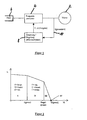
- Figure 2 shows an engine diagram, wherein the engine speed N is plotted as a function of the engine torque M, ie as a function of the load of the electric motor. Up to a limiting current I (limit) , the frequency of the motor exciter voltage and also the magnitude of this voltage is kept constant. Thus, the electric motor runs at approximately constant speed N in the area designated I.
- I limit
- the frequency of the motor excitation voltage is controlled by the motor control device so that the motor current I remains constant, preferably at the limit I (grenz) , which is between 10 and 20 A. , in particular between 10 and 15 A and preferably for example in an angle grinder motor is 12 to 14 A.
- the limit I (grenz) which is between 10 and 20 A. , in particular between 10 and 15 A and preferably for example in an angle grinder motor is 12 to 14 A.
- the frequency of the motor exciter voltage applied to the motor by the frequency converter and thus also the motor speed M.
- the characteristics of a commutator motor are more or less out of the controllable range.
- the power tool according to the invention behaves as users of devices with universal motors are used, so that the speed of the motor noticeably decreases with increasing load. This area is indicated in Fig. 2 with II.
Landscapes
- Engineering & Computer Science (AREA)
- Power Engineering (AREA)
- Control Of Motors That Do Not Use Commutators (AREA)
- Control Of Ac Motors In General (AREA)
- Electrical Discharge Machining, Electrochemical Machining, And Combined Machining (AREA)
- Surgical Instruments (AREA)
Description
- Die Erfindung betrifft ein Elektrowerkzeuggerät, insbesondere ein Elektrohandwerkzeuggerät, mit einem Asynchronelektromotor oder einem bürstenlosen Synchronelektromotor und einer rechnergesteuerten Motorsteuereinrichtung, also mit einer insbesondere mikroprozessorgesteuerten Steuerelektronik.
- Elektrohandwerkzeuggeräte werden überwiegend von Elektromotoren mit einem Stromwender oder Kommutator in Verbindung mit Kohlebürsten angetrieben, insbesondere kommen sogenannte Universalmotoren zum Einsatz. Kohlebürsten unterliegen einem stetigen Verschleiß und müssen nach einiger Zeit ausgewechselt werden. Derartige Stromwendermotoren haben bis zu einer gewissen Belastung eine nahezu lineare Leistungscharakteristik derart, dass bei höherer Belastung die Motordrehzahl sinkt, wobei der Motorstrom ansteigt. Es gibt aber auch Elektrohandwerkzeuggeräte mit geregelten Stromwendermotoren. Dabei wird meist über eine Phasenanschnittsteuerung die Motordrehzahl bei ansteigender Belastung konstant gehalten, wie z. B. bei dem von der Anmelderin unter dem Handelsnamen "Vario-Constamatik" vertriebenen Elektrowerkzeuggerät. Übersteigt jedoch die Belastung des Motors einen gewissen Wert, so kann nicht mehr durch die Steuerelektronik nachgeregelt werden, und es ergibt sich dann zwangsläufig die Kennlinie des ungeregelten Motors.
- Es ist auch bekannt, bei sogenannten halbstationären Elektrowerkzeuggeräten, wie z. B. Tischkreissägen, Tischhobelmaschinen, Bandrichtmaschinen, etc., einen Asynchronelektromotor oder einen Synchronelektromotor einzusetzen, die mit einer konstanten Frequenz der Motorerregerspannung betrieben werden. Insbesondere wird hierbei als Frequenz die Netzfrequenz, in Europa also 50 Hertz bzw. in den USA 60 Hertz gewählt. Mit DE 298 09 768 U1 ist ein halbstationäres Elektrowerkzeuggerät in Form einer Tischkreissäge bekannt geworden mit einem Asynchronelektromotor oder einem Synchronelektromotor, der jedoch unter Verwendung eines Frequenzumrichters bei einer gegenüber der Netzfrequenz höheren konstanten Frequenz von 300 bis 400 Hertz betrieben wird. Infolgedessen ist auch die Motordrehzahl entsprechend erhöht, und es ist im Antriebsmotor ein Untersetzungsgetriebe nachgeordnet.
- Aus DE 198 16 684 A1 ist ein Elektrohandwerkzeuggerät mit einem kohlebürstenlosen Elektromotor beschrieben, wobei eine den Antriebsmotor und die unmittelbar für dessen Ansteuerung notwendigen elektrischen Bauteile der Motorsteuerung enthaltende Geräteeinheit und eine externe separate Stromversorgungseinheit vorgesehen ist.
- Ferner ist aus DE 19944194 A1 ein elektronisch kommutierbarer Motor mit Überlastschutz, bekannt.
- Aufgabe der vorliegenden Erfindung ist es, ein Elektrowerkzeuggerät zu schaffen, welches eine lineare Leistungscharakteristik wie bei einem Kohlebürsten aufweisenden Stromwendermotor aufweist, ohne jedoch ein verschleißanfälliges Kommutator-Kohlebürsten-System zu benötigen. Die Motorsteuereinrichtung soll auch ohne aufwändige Sensoren, wie z. B. Tachosensoren, Hall-Sensoren, auskommen.
- Diese Aufgabe wird bei einem Elektrohandwerkzeuggerät der genannten Art gelöst, welches gekennzeichnet ist durch einen von der Motorsteuereinrichtung steuerbaren Frequenzumrichter, mittels dessen eine Motor (erreger) spannung an den Motor anlegbar ist, und durch einen den Motorstrom erfassenden und mit der Motorsteuereinrichtung zusammenwirkenden Stromaufnehmer, und dadurch, dass die Motorsteuereinrichtung so ausgebildet ist, dass in einer ersten Phase des Motorbetriebs bei Motorströmen bis zu einem Grenzstrom I(grenz) die Frequenz des Motorstroms konstant gehalten wird und dass in einer zweiten Phase des Motorbetriebs bei Belastungen oberhalb derjenigen Belastung, bei der der Motorstrom den Grenzstrom I(grenz) erreicht, die Frequenz des Motorstroms so herabgesetzt wird, dass der Motorstrom bei einem konstanten Wert gehalten wird. - Wenn vorstehend von einem Grenzstrom I(grenz) die Rede ist, so wird hierunter eine Erregerstromstärke verstanden, die unterhalb des Kipp-Punkts liegt, also unterhalb derjenigen Stromstärke, bei der der Elektromotor stehen bleibt. Vorzugsweise wird der Grenzstrom zwischen 5 und 15 % geringer gewählt als die Stromstärke am Kipp-Punkt. Bei starken Elektromotoren kann der Grenzstrom I(grenz) zwischen 15 und 20 A liegen und bei schwach belastbaren Elektromotoren bei 4-8 A.
- Der Antriebsmotor wird also bis zu einer Belastung, die einem Grenzstrom I(grenz) entspricht, mit einer konstanten Frequenz F betrieben. Dies ergibt eine nahezu waagerechte Motorkennlinie, wenn man die Motordrehzahl N in Abhängigkeit von der Belastung bzw. dem vom Motor erbrachten Drehmoment M aufträgt. Bei Erhöhung der Belastung, also mit zunehmendem Drehmoment M, sinkt die Motordrehzahl N nur unwesentlich aufgrund des sogenannten Schlupfes des Elektromotors. Damit entspricht dieser erste Betriebsbereich im Prinzip der normalen Kennlinie eines ungeregelten Synchron- oder Asynchronelektromotors bei Belastungen in hinreichender Entfernung vom sogenannten Kipp-Punkt. Andererseits entspricht dieser Bereich der Kennlinie auch in etwa der Kennlinie eines über Phasenanschnittsteuerung geregelten Universalmotors (Reihenschlussmotors) mit einem Kommutator-Kohlebürsten-System.
- Wenn die Belastung bzw. das vom Elektromotor aufgebrachte Drehmoment einer bestimmten Größe I(grenz) des Motorstroms entspricht, wird der Antriebsmotor mittels der Motorsteuereinrichtung mit einer variablen Frequenz betrieben, und zwar derart, dass der Motorstrom I konstant bleibt. Wenn vorliegend vom Motorstrom die Rede ist, so wird hierunter der durch Wicklungen des Ständers oder Stators des Motors fließende Motorerregerstrom verstanden. Es wird also in diesem zweiten Belastungsbereich eine bestimmte Größe des Motorstroms I durch Veränderung der Frequenz eingeregelt. In vorteilhafter Weiterbildung des Elektrowerkzeuggeräts ist die Motorsteuereinrichtung so ausgebildet, dass der Motorstrom während dieser zweiten Phase auf dem konstanten Wert I(grenz) gehalten wird.
- Nach einer weiteren bevorzugten Ausführungsform der Erfindung ist die Motorsteuereinrichtung so ausgebildet, dass die an den Motor angelegte Spannung (die Motorerregerspannung) während dieser zweiten Phase ebenfalls auf einem konstanten Wert gehalten wird. Vorteilhafterweise ist die Motorsteuereinrichtung so ausgebildet, dass die an den Motor angelegte Spannung während der ersten und der zweiten Phase auf einem konstanten, insbesondere dem gleichen Wert gehalten wird.
- Zur Ausführung des vorstehend erwähnten Regelvorgangs hat es sich als vorteilhaft erwiesen, wenn der Stromaufnehmer einen Shunt-Widerstand umfasst, der in vorteilhafter Weise direkt über einen Spannungsabgriff als Strommessmittel verwendet werden kann.
- Es hat sich des Weiteren als vorteilhaft erwiesen, wenn in Abhängigkeit von der Auslegung der geforderten Motorleistung die Größe des Grenzstroms I(grenz) zwischen 4 und 20 Ampere, insbesondere zwischen 10 und 15 Ampere gewählt ist.
- Es erweist sich des Weiteren als zweckmäßig, wenn der Frequenzumrichter und die Motorsteuereinrichtung sowie der den Motorstrom erfassende Stromaufnehmer auf einer gemeinsamen Platine ausgebildet und/oder in einem geschlossenen Elektronikgehäuse angeordnet sind und somit als einzige Baugruppe verbaubar sind.
- In weiterer Ausbildung der Erfindung von besonderer Bedeutung ist die Motorsteuereinrichtung so ausgebildet, dass während einer dritten Phase des Motorbetriebs, die dadurch gekennzeichnet ist, dass sich der Motorstrom bei weiter ansteigender Belastung nicht mehr allein durch Absenken der Frequenz des Motorstroms konstant halten lässt, auch die Motorspannung abgesenkt wird. Wenn also die vorstehend beschriebene Motorregelung während der zweiten Phase bei weiter ansteigender Belastung an ihre Grenzen stößt, weil durch weitere Absenkung der Frequenz der Motorstrom nicht mehr konstant gehalten werden kann, so stößt der Motor an eine Regelgrenze. Es wird nun in Weiterbildung der Erfindung vorgeschlagen, sowohl die Frequenz als auch die Motorspannung zu verändern, und zwar abzusenken, mit der Folge, dass die Motordrehzahl sehr stark und für den Benutzer spürbar abnimmt, sodass der Benutzer schnell merkt, dass der Motor überlastet ist und die Belastung entsprechend absenken kann. Damit wird ein Kippen des Motors verhindert.
- In weiterer Ausbildung dieses Erfindungsgedankens kann die Motorsteuerung so ausgebildet sein, dass bei Erreichen einer Motorspannung U(grenz) während der dritten Phase der Motor dann abgeschaltet wird oder dass anstelle eines Abschaltens des Motors eine Resterregung an den Motor angelegt wird, damit nach Wegnahme der Belastung der Motor selbsttätig wieder anlaufen kann und damit in den normalen Regelbetrieb eingetreten werden kann.
- Die Erfindung betrifft aber auch ein Verfahren zum Betreiben eines Elektrohandwerkzeuggeräts mit einem Asynchronelektromotor oder einem bürstenlosen Synchronelektromotor und einer rechnergesteuerten Motorsteuereinrichtung mit den Merkmalen des Anspruchs 11. Bevorzugte Ausführungsformen dieses erfindungsgemäßen Verfahrens ergeben sich aus den Ansprüchen 12 bis 18.
- Mit dem erfindungsgemäßen Elektrowerkzeuggerät und unter Ausführung des erfindungsgemäßen Verfahrens zum Betreiben eines Elektrowerkzeuggeräts kann eine Motorcharakteristik oder Leistungscharakteristik erhalten werden, wie sie ein Benutzer von Elektrowerkzeuggeräten mit einem Kohlebürsten aufweisenden Kommutatorsystem, von sogenannten Universalmotoren, gewohnt ist, ohne dass jedoch ein solches Verschleiß behaftetes Kommutator-Kohlebürsten-System zum Einsatz kommt. Auf der anderen Seite erweist es sich als vorteilhaft, dass trotz Verwendung von Asynchronelektromotoren oder bürstenlosen Synchronelektromotoren das bei diesen Motoren an sich übliche "Kippen" des Motors verhindert werden kann. Der Motor wird stets in einem für die gerade auftretende Belastung optimalen Betriebspunkt durch Wahl der optimalen Frequenz betrieben.
- Weitere Merkmale, Einzelheiten und Vorteile der Erfindung ergeben sich aus den beigefügten Patentansprüchen und der zeichnerischen Darstellung und nachfolgenden Beschreibung einer bevorzugten Ausführungsform der Erfindung. In der Zeichnung zeigt:
- Fig. 1
- in schematischer Darstellung die Schaltung eines erfindungsgemäßen Elektrohandwerkzeuggeräts.
- Fig. 2
- ein Motordiagramm durch Auftragung der Motordrehzahl N über dem Motordrehmoment M.
- Figur 1 zeigt schematisch den grundsätzlichen Aufbau der Motorsteuerung bei einem erfindungsgemäßen Elektrowerkzeuggerät. Der Motor 2, ein Asynchronelektromotor oder ein bürstenloser Synchronelektromotor, ist an einen mit Netzspannung gespeisten Frequenzumrichter 4 angeschlossen, von dem er die Motorversorgungs- oder Motorerregerspannung erhält. Der Freqenzumrichter 4 ist an das normale Stromnetz 6 mit z. B. 230 V/50Hz angeschlossen. Ferner ist eine mikroprozessorbetriebene Motorsteuereinrichtung 8 vorgesehen, welche den Frequenzumrichter 4 ansteuert und die Vorgabe für die Frequenz der Motorerregerspannung sowie für die Größe der Motorerregerspannung an den Frequenzumrichter 4 gibt. Ferner ist ein Stromaufnehmer 10 in einer jeweiligen Ansteuerleitung zwischen Frequenzumrichter 4 und Elektromotor 2 vorgesehen. Es kann sich hierbei in vorteilhafter Weise um einen Shunt-Widerstand 12 handeln, mittels dessen über an sich bekannte und daher nicht dargestellte elektronische Abgriffsschaltungen eine dem Motorstrom entsprechende Größe erzeugt und der Motorsteuereinrichtung 8 als Eingangsgröße eingegeben werden kann. Der Frequenzumrichter 4, die Motorsteuereinrichtung 8 sowie der Stromwertaufnehmer 10 mit nicht dargestellter Schaltung sind in einem Maschinengehäuse des Elektrowerkzeuggeräts auf einer gemeinsamen Platine oder in einem gegen Feuchtigkeit geschützten Elektronikgehäuse als Baugruppe angeordnet bzw. untergebracht.
- Figur 2 zeigt ein Motordiagramm, wobei die Motordrehzahl N als Funktion des Motordrehmoments M, also als Funktion der Belastung des Elektromotors aufgetragen ist. Bis zu einem Grenzstrom I(grenz) wird die Frequenz der Motorerregerspannung und auch die Größe dieser Spannung konstant gehalten. Damit läuft der Elektromotor mit etwa konstanter Drehzahl N in dem mit I bezeichneten Gebiet.
- Steigt der Motorstrom infolge zunehmender Belastung über den Grenzwert I(grenz), so wird über die Motorsteuereinrichtung die Frequenz der Motorerregerspannung so geregelt, dass der Motorstrom I konstant bleibt, und zwar vorzugsweise auf dem Grenzwert I(grenz), der zwischen 10 und 20 A, insbesondere zwischen 10 und 15 A und vorzugsweise beispielsweise bei einem Winkelschleifer-Motor bei 12 bis 14 A liegt. Mit steigender Belastung sinkt damit, die Frequenz der durch den Frequenzumrichter an den Motor angelegten Motorerregerspannung und damit auch die Motordrehzahl M. Man hat daher in etwa die Charakteristik eines Stromwendermotors, außerhalb des regelbaren Bereichs. Damit verhält sich das erfindungsgemäße Elektrowerkzeuggerät so, wie es Benutzer von Geräten mit Universalmotoren gewohnt sind, also dass die Drehzahl des Motors mit steigender Belastung spürbar sinkt. Dieses Gebiet ist in Fig. 2 mit II bezeichnet.
- Wenn die Belastung weiter ansteigt, so wird am Ende des Gebiets II die Grenze der Regelbarkeit erreicht, was bedeutet, dass der Motorstrom nicht mehr allein durch Reduzieren der Frequenz der Motorerregerspannung konstant gehalten werden kann. Es wird in Weiterbildung der Erfindung dann sowohl die Frequenz als auch die Spannung reduziert, damit der Motorstrom I weiterhin auf gleichem Niveau gehalten werden kann. In diesem mit III bezeichneten Gebiet des Motordiagramms fällt dann die Kennlinie steil ab, d. h. die Motordrehzahl N nimmt mit der Belastung sehr stark ab, sodass ein Benutzer ohne Weiteres erkennen kann, dass der Motor in überlastetem Zustand dreht und dann die Belastung entsprechend reduzieren kann. Durch diese Steuerung im Gebiet III wird das Kippen des Motors verhindert. Bei Erreichen einer Grenzspannung U(grenz) wird der Motor dann sicherheitshalber abgeschaltet, da andernfalls der Motorstrom nicht weiter konstant gehalten werden könnte. Alternativ hierzu kann eine geringe Resterregung aufrecht erhalten werden, sodass nach Wegnahme der Belastung der Motor wieder langsam anlaufen kann und dann selbsttätig wieder in den regelbaren Bereich gelangen kann.
Claims (18)
- Elektrowerkzeuggerät, insbesondere Elektrohandwerkzeuggerät, mit einem Asynchronelektromotor (2) oder einem bürstenlosen Synchronelektromotor und einer rechnergesteuerten Motorsteuereinrichtung (8), gekennzeichnet durch einen von der Motorsteuereinrichtung steuerbaren Frequenzumrichter (4), mittels dessen eine Motor(erreger)spannung an den Motor (2) anlegbar ist, und durch einen den Motorstrom erfassenden und mit der Motorsteuereinrichtung (8) zusammenwirkenden Stromaufnehmer (10), und dadurch, dass die Motorsteuereinrichtung (8) so ausgebildet ist, dass in einer ersten Phase des Motorbetriebs bei Motorströmen bis zu einem Grenzstrom I(grenz) die an den Motor angelegte Spannung und die Frequenz des Motorstroms konstant gehalten wird und dass in einer zweiten Phase des Motorbetriebs bei Belastungen oberhalb derjenigen Belastung, bei der der Motorstrom den Grenzstrom I(grenz) erreicht, die an den Motor angelegte Spannung konstant gehalten wird und die Frequenz des Motorstroms so herabgesetzt wird, dass der Motorstrom bei einem konstanten Wert gehalten wird.
- Elektrowerkzeuggerät nach Anspruch 1, dadurch gekennzeichnet, dass die Motorsteuereinrichtung (8) so ausgebildet ist, dass der Motorstrom während der zweiten Phase auf dem konstanten Wert I(grenz) gehalten wird.
- Elektrowerkzeuggerät nach Anspruch 1 oder 2, dadurch gekennzeichnet, dass die Motorsteuereinrichtung (8) so ausgebildet ist, dass die an den Motor angelegte Spannung während der ersten und der zweiten Phase auf dem gleichen Wert gehalten wird.
- Elektrowerkzeuggerät nach einem oder mehreren der vorstehenden Ansprüche, dadurch gekennzeichnet, dass der Stromaufnehmer (10) einen Shunt-Widerstand (12) umfasst.
- Elektrowerkzeuggerät nach einem oder mehreren der vorstehenden Ansprüche, dadurch gekennzeichnet, dass der Frequenzumrichter (4) und die Motorsteuereinrichtung (8) im Gehäuse des Elektrowerkzeuggeräts untergebracht sind.
- Elektrowerkzeuggerät nach einem oder mehreren der vorstehenden Ansprüche, dadurch gekennzeichnet, dass der Grenzstrom I(grenz) zwischen 4 und 20 A, insbesondere zwischen 10 und 15 A gewählt ist.
- Elektrowerkzeuggerät nach einem oder mehreren der vorstehenden Ansprüche, dadurch gekennzeichnet, dass der Frequenzumrichter (4) und die Motorsteuereinrichtung (8) auf einer gemeinsamen Platine ausgebildet und/oder in einem geschlossenen Elektronikgehäuse angeordnet sind.
- Elektrowerkzeuggerät nach einem oder mehreren der vorstehenden Ansprüche, dadurch gekennzeichnet, dass die Motorsteuereinrichtung (8) so ausgebildet ist, dass während einer dritten Phase des Motorbetriebs, die
dadurch gekennzeichnet ist, dass sich der Motorstrom bei weiter ansteigender Belastung nicht mehr allein durch Absenken der Frequenz des Motorstroms konstant halten lässt, auch die Motorspannung abgesenkt wird. - Elektrowerkzeuggerät nach Anspruch 8, dadurch gekennzeichnet, dass die Motorsteuereinrichtung (8) so ausgebildet ist, dass bei Erreichen einer Motorspannung U(grenz) während der dritten Phase der Motor abgeschaltet wird.
- Elektrowerkzeuggerät nach Anspruch 8, dadurch gekennzeichnet, dass die Motorsteuereinrichtung (8) so ausgebildet ist, dass bei Erreichen einer Motorspannung U(grenz) während der dritten Phase anstelle eines Abschaltens des Motors eine Resterregung an den Motor angelegt wird, damit nach Wegnahme der Belastung der Motor selbsttätig wieder anläuft.
- Verfahren zum Betreiben eines Elektrowerkzeuggeräts, insbesondere Elektrohandwerkzeuggeräts mit einem Asynchronelektromotor oder einem bürstenlosen Synchronelektromotor und einer rechnergesteuerten Motorsteuereinrichtung, dadurch gekennzeichnet, dass während einer ersten Phase des Motorbetriebs unter geringer Belastung bei Motorströmen bis zu einem Grenzstrom I(grenz) die an den Motor angelegte Spannung und die Frequenz des Motorstroms konstant gehalten wird und dass in einer zweiten Phase des Motorbetriebs bei Belastungen oberhalb derjenigen Belastung, bei der der Motorstrom den Grenzstrom I(grenz) erreicht, die an den Motor angelegte Spannung konstant gehalten wird und die Frequenz des Motorstroms so herabgesetzt wird, dass der Motorstrom bei einem konstanten Wert gehalten wird.
- Verfahren nach Anspruch 11, dadurch gekennzeichnet, dass der Motorstrom während der zweiten Phase auf dem konstante Wert I(grenz) gehalten wird.
- Verfahren nach Anspruch 11 oder 12, dadurch gekennzeichnet, dass die an den Motor angelegte Spannung während der zweiten Phase auf einem konstanten Wert gehalten wird.
- Verfahren nach Anspruch 11, 12 oder 13, dadurch gekennzeichnet, dass die an den Motor angelegte Spannung während der ersten und der zweiten Phase auf einem konstanten, insbesondere dem gleichen Wert gehalten wird.
- Verfahren nach einem oder mehreren der Ansprüche 11 bis 14, dadurch gekennzeichnet, dass der Grenzstrom I(grenz) zwischen 10 und 20 A, insbesondere zwischen 10 und 15. A gewählt wird.
- Verfahren nach einem oder mehreren der Ansprüche 11 bis 15, dadurch gekennzeichnet, dass während einer dritten Phase des Motorbetriebs, die dadurch gekennzeichnet ist, dass sich der Motorstrom bei weiter ansteigender Belastung nicht mehr allein durch Absenken der Frequenz des Motorstroms konstant halten lässt, auch die Motorspannung abgesenkt wird.
- Verfahren nach Anspruch 16, dadurch gekennzeichnet, dass bei Erreichen einer Motorspannung U(grenz) während der dritten Phase der Motor abgeschaltet wird.
- Verfahren nach Anspruch 16, dadurch gekennzeichnet, dass bei Erreichen einer Motorspannung U(grenz) während der dritten Phase anstelle eines Abschaltens des Motors eine Resterregung an den Motor angelegt wird, damit nach Wegnahme der Belastung der Motor selbsttätig wieder anläuft.
Applications Claiming Priority (3)
| Application Number | Priority Date | Filing Date | Title |
|---|---|---|---|
| DE2002116836 DE10216836B4 (de) | 2002-04-16 | 2002-04-16 | Elektrowerkzeuggerät |
| DE10216836 | 2002-04-16 | ||
| PCT/EP2003/003111 WO2003088470A1 (de) | 2002-04-16 | 2003-03-26 | Elektrowerkzeuggerät |
Publications (2)
| Publication Number | Publication Date |
|---|---|
| EP1518316A1 EP1518316A1 (de) | 2005-03-30 |
| EP1518316B1 true EP1518316B1 (de) | 2007-01-03 |
Family
ID=28798446
Family Applications (1)
| Application Number | Title | Priority Date | Filing Date |
|---|---|---|---|
| EP20030714880 Expired - Lifetime EP1518316B1 (de) | 2002-04-16 | 2003-03-26 | Elektrowerkzeuggerät |
Country Status (7)
| Country | Link |
|---|---|
| US (1) | US7268509B2 (de) |
| EP (1) | EP1518316B1 (de) |
| AT (1) | ATE350806T1 (de) |
| AU (1) | AU2003219098A1 (de) |
| DE (2) | DE10216836B4 (de) |
| ES (1) | ES2279942T3 (de) |
| WO (1) | WO2003088470A1 (de) |
Families Citing this family (5)
| Publication number | Priority date | Publication date | Assignee | Title |
|---|---|---|---|---|
| DE102006051507A1 (de) * | 2006-10-31 | 2008-05-08 | Kaltenbach & Voigt Gmbh | Steuervorrichtung für den Antrieb eines mit einem geregelten Elektromotor betriebenen Dentalhandstückes |
| US8212511B2 (en) * | 2008-10-22 | 2012-07-03 | Kelsey-Hayes Company | Method and apparatus for limiting torque in an electric drive motor |
| CN103368480B (zh) * | 2012-03-31 | 2016-11-16 | 苏州宝时得电动工具有限公司 | 手持电动工具及其控制方法 |
| CN103368483B (zh) * | 2012-03-31 | 2016-02-17 | 苏州宝时得电动工具有限公司 | 手持电动工具及其控制方法 |
| US11689124B2 (en) | 2021-01-12 | 2023-06-27 | Snap-On Incorporated | Controlling brushless motor commutation |
Family Cites Families (10)
| Publication number | Priority date | Publication date | Assignee | Title |
|---|---|---|---|---|
| DE3125157A1 (de) * | 1981-06-26 | 1983-01-13 | Licentia Patent-Verwaltungs-Gmbh, 6000 Frankfurt | Drehzahlregelschaltung fuer einen motor |
| DK1984A (da) | 1984-01-03 | 1985-07-04 | Grundfos As | Fremgangsmaade til regulering af en vekselstroemsmotor |
| DE3709983A1 (de) * | 1987-03-26 | 1988-10-13 | Festo Kg | Stromversorgungseinrichtung fuer elektrowerkzeuge |
| DE19629564C2 (de) * | 1996-07-15 | 2000-10-19 | Glibitski Marks | Kleiner Hochleistungselektroantrieb für Asynchron-, Synchron -und andere Wechselstrommotoren |
| WO1999003193A1 (de) | 1997-07-11 | 1999-01-21 | Barmag Ag | Verfahren zum steuern eines elektrischen motors |
| DE29809768U1 (de) * | 1998-05-20 | 1999-09-23 | Elektra Beckum Ag, 49716 Meppen | Tragbare Werkzeugmaschine, insbesondere Tischkreissäge |
| US6166502A (en) * | 1999-04-01 | 2000-12-26 | Delphi Technologies, Inc. | Thermal current limiting apparatus and method for vehicle system with electric motor actuator |
| DE19944194A1 (de) * | 1999-09-15 | 2001-03-22 | Bosch Gmbh Robert | Elektronisch kommutierbarer Motor mit Überlastschutz |
| JP2002199773A (ja) * | 2000-12-27 | 2002-07-12 | Sanden Corp | 圧縮機モータ駆動制御方法及び圧縮機駆動用インバータ装置 |
| JP4055992B2 (ja) * | 2002-12-25 | 2008-03-05 | サンデン株式会社 | インバータの電流検出装置 |
-
2002
- 2002-04-16 DE DE2002116836 patent/DE10216836B4/de not_active Expired - Fee Related
-
2003
- 2003-03-26 AT AT03714880T patent/ATE350806T1/de active
- 2003-03-26 AU AU2003219098A patent/AU2003219098A1/en not_active Abandoned
- 2003-03-26 DE DE50306198T patent/DE50306198D1/de not_active Expired - Lifetime
- 2003-03-26 ES ES03714880T patent/ES2279942T3/es not_active Expired - Lifetime
- 2003-03-26 US US10/510,693 patent/US7268509B2/en not_active Expired - Lifetime
- 2003-03-26 EP EP20030714880 patent/EP1518316B1/de not_active Expired - Lifetime
- 2003-03-26 WO PCT/EP2003/003111 patent/WO2003088470A1/de not_active Ceased
Also Published As
| Publication number | Publication date |
|---|---|
| DE10216836A1 (de) | 2003-11-06 |
| ATE350806T1 (de) | 2007-01-15 |
| WO2003088470A1 (de) | 2003-10-23 |
| US7268509B2 (en) | 2007-09-11 |
| AU2003219098A1 (en) | 2003-10-27 |
| EP1518316A1 (de) | 2005-03-30 |
| ES2279942T3 (es) | 2007-09-01 |
| US20050162112A1 (en) | 2005-07-28 |
| DE50306198D1 (de) | 2007-02-15 |
| DE10216836B4 (de) | 2005-09-22 |
Similar Documents
| Publication | Publication Date | Title |
|---|---|---|
| AT504808B1 (de) | Synchronmaschine | |
| DE3247046A1 (de) | Verfahren und einrichtung zum speisen einer handgefuehrten werkzeugmaschine mit einem kollektorlosen elektromotor | |
| CH621656A5 (de) | ||
| EP2087571A1 (de) | Umrichter mit steuerbarem phasenwinkel | |
| DE102005024068A1 (de) | Verfahren zur Steuerung eines aus einem Gleichspannungsnetz gespeisten Elektromotors | |
| EP2244372B1 (de) | Schaltungsanordnung zum Einsatz bei einer Windenergieanlage | |
| EP1518316B1 (de) | Elektrowerkzeuggerät | |
| DE3900219C2 (de) | Fahrzeugsitz mit motorbetriebener Verstellung der Rückenlehne und der Sitzschiene | |
| EP0283945A2 (de) | Stromversorgungseinrichtung für Elektrowerkzeuge | |
| EP2085191B1 (de) | Antriebsgerät für Werkzeuge, vorzugsweise für Kernbohrkronen | |
| DE4201005C2 (de) | Schaltungsanordnung zum netzunabhängigen, aussetzerfreien Bremsen eines Reihenschlußmotors | |
| DE19912121A1 (de) | Reihenschlußmotor | |
| DE112018006979T5 (de) | Elektrischer Kompressor | |
| DE8808570U1 (de) | Vorrichtung mit Einschaltautomatik für ein Nebengerät bei Inbetriebnahme eines Hauptgerätes | |
| DE3442607A1 (de) | Ueberlast-schutzschaltung fuer eine stromrichteranordnung | |
| AT519142B1 (de) | Verfahren und Vorrichtung zum Abbauen elastisch gespeicherter Energie | |
| EP1163716B1 (de) | Steuerelektronik für ein elektrohandwerkzeug | |
| DE2310835A1 (de) | Reihenschluss-kommutatormotor | |
| DE3819166A1 (de) | Schaltanordnung zur drehzahlsteuerung eines reihenschlussmotors mit drehmomentabschaltung | |
| EP1022845A2 (de) | Verfahren und Vorrichtung zum Betreiben eines Elektromotors eines Dokumentenvernichters | |
| DE102007025985B3 (de) | Steuereinrichtung für ein Elektrohandwerkzeug | |
| DE3501947A1 (de) | Elektrowerkzeug, insbesondere winkelschleifer | |
| EP2319976B1 (de) | Hausgerät zur Pflege von Wäschestücken und Verfahren zum Betreiben eines bürstenbehafteten Gleichstrommotors | |
| DE3223655A1 (de) | Einrichtung zur regelung eines wechselstrom-induktionsmotors | |
| EP4002677A1 (de) | Türsystem für ein fahrzeug mit einem türflügel und verfahren zum selektiven abbremsen eines elektrisch antreibbaren türflügels |
Legal Events
| Date | Code | Title | Description |
|---|---|---|---|
| PUAI | Public reference made under article 153(3) epc to a published international application that has entered the european phase |
Free format text: ORIGINAL CODE: 0009012 |
|
| 17P | Request for examination filed |
Effective date: 20050120 |
|
| AK | Designated contracting states |
Kind code of ref document: A1 Designated state(s): AT BE BG CH CY CZ DE DK EE ES FI FR GB GR HU IE IT LI LU MC NL PT RO SE SI SK TR |
|
| AX | Request for extension of the european patent |
Extension state: AL LT LV MK |
|
| GRAP | Despatch of communication of intention to grant a patent |
Free format text: ORIGINAL CODE: EPIDOSNIGR1 |
|
| RIC1 | Information provided on ipc code assigned before grant |
Ipc: H02P 3/18 20060101AFI20060607BHEP |
|
| GRAS | Grant fee paid |
Free format text: ORIGINAL CODE: EPIDOSNIGR3 |
|
| GRAA | (expected) grant |
Free format text: ORIGINAL CODE: 0009210 |
|
| AK | Designated contracting states |
Kind code of ref document: B1 Designated state(s): AT BE BG CH CY CZ DE DK EE ES FI FR GB GR HU IE IT LI LU MC NL PT RO SE SI SK TR |
|
| PG25 | Lapsed in a contracting state [announced via postgrant information from national office to epo] |
Ref country code: NL Free format text: LAPSE BECAUSE OF FAILURE TO SUBMIT A TRANSLATION OF THE DESCRIPTION OR TO PAY THE FEE WITHIN THE PRESCRIBED TIME-LIMIT Effective date: 20070103 Ref country code: IE Free format text: LAPSE BECAUSE OF FAILURE TO SUBMIT A TRANSLATION OF THE DESCRIPTION OR TO PAY THE FEE WITHIN THE PRESCRIBED TIME-LIMIT Effective date: 20070103 Ref country code: SI Free format text: LAPSE BECAUSE OF FAILURE TO SUBMIT A TRANSLATION OF THE DESCRIPTION OR TO PAY THE FEE WITHIN THE PRESCRIBED TIME-LIMIT Effective date: 20070103 Ref country code: FI Free format text: LAPSE BECAUSE OF FAILURE TO SUBMIT A TRANSLATION OF THE DESCRIPTION OR TO PAY THE FEE WITHIN THE PRESCRIBED TIME-LIMIT Effective date: 20070103 Ref country code: DK Free format text: LAPSE BECAUSE OF FAILURE TO SUBMIT A TRANSLATION OF THE DESCRIPTION OR TO PAY THE FEE WITHIN THE PRESCRIBED TIME-LIMIT Effective date: 20070103 |
|
| REG | Reference to a national code |
Ref country code: GB Ref legal event code: FG4D Free format text: NOT ENGLISH |
|
| REF | Corresponds to: |
Ref document number: 50306198 Country of ref document: DE Date of ref document: 20070215 Kind code of ref document: P |
|
| REG | Reference to a national code |
Ref country code: IE Ref legal event code: FG4D Free format text: LANGUAGE OF EP DOCUMENT: GERMAN |
|
| GBT | Gb: translation of ep patent filed (gb section 77(6)(a)/1977) |
Effective date: 20070207 |
|
| PG25 | Lapsed in a contracting state [announced via postgrant information from national office to epo] |
Ref country code: SE Free format text: LAPSE BECAUSE OF FAILURE TO SUBMIT A TRANSLATION OF THE DESCRIPTION OR TO PAY THE FEE WITHIN THE PRESCRIBED TIME-LIMIT Effective date: 20070403 |
|
| PG25 | Lapsed in a contracting state [announced via postgrant information from national office to epo] |
Ref country code: BG Free format text: LAPSE BECAUSE OF EXPIRATION OF PROTECTION Effective date: 20070404 |
|
| PG25 | Lapsed in a contracting state [announced via postgrant information from national office to epo] |
Ref country code: PT Free format text: LAPSE BECAUSE OF FAILURE TO SUBMIT A TRANSLATION OF THE DESCRIPTION OR TO PAY THE FEE WITHIN THE PRESCRIBED TIME-LIMIT Effective date: 20070604 |
|
| NLV1 | Nl: lapsed or annulled due to failure to fulfill the requirements of art. 29p and 29m of the patents act | ||
| ET | Fr: translation filed | ||
| REG | Reference to a national code |
Ref country code: IE Ref legal event code: FD4D |
|
| REG | Reference to a national code |
Ref country code: ES Ref legal event code: FG2A Ref document number: 2279942 Country of ref document: ES Kind code of ref document: T3 |
|
| PLBE | No opposition filed within time limit |
Free format text: ORIGINAL CODE: 0009261 |
|
| STAA | Information on the status of an ep patent application or granted ep patent |
Free format text: STATUS: NO OPPOSITION FILED WITHIN TIME LIMIT |
|
| PG25 | Lapsed in a contracting state [announced via postgrant information from national office to epo] |
Ref country code: SK Free format text: LAPSE BECAUSE OF FAILURE TO SUBMIT A TRANSLATION OF THE DESCRIPTION OR TO PAY THE FEE WITHIN THE PRESCRIBED TIME-LIMIT Effective date: 20070103 |
|
| 26N | No opposition filed |
Effective date: 20071005 |
|
| BERE | Be: lapsed |
Owner name: METABOWERKE G.M.B.H. Effective date: 20070331 |
|
| PG25 | Lapsed in a contracting state [announced via postgrant information from national office to epo] |
Ref country code: BE Free format text: LAPSE BECAUSE OF NON-PAYMENT OF DUE FEES Effective date: 20070331 Ref country code: CZ Free format text: LAPSE BECAUSE OF FAILURE TO SUBMIT A TRANSLATION OF THE DESCRIPTION OR TO PAY THE FEE WITHIN THE PRESCRIBED TIME-LIMIT Effective date: 20070103 Ref country code: RO Free format text: LAPSE BECAUSE OF FAILURE TO SUBMIT A TRANSLATION OF THE DESCRIPTION OR TO PAY THE FEE WITHIN THE PRESCRIBED TIME-LIMIT Effective date: 20070103 |
|
| PG25 | Lapsed in a contracting state [announced via postgrant information from national office to epo] |
Ref country code: MC Free format text: LAPSE BECAUSE OF NON-PAYMENT OF DUE FEES Effective date: 20070331 |
|
| PG25 | Lapsed in a contracting state [announced via postgrant information from national office to epo] |
Ref country code: GR Free format text: LAPSE BECAUSE OF FAILURE TO SUBMIT A TRANSLATION OF THE DESCRIPTION OR TO PAY THE FEE WITHIN THE PRESCRIBED TIME-LIMIT Effective date: 20070404 |
|
| PG25 | Lapsed in a contracting state [announced via postgrant information from national office to epo] |
Ref country code: EE Free format text: LAPSE BECAUSE OF FAILURE TO SUBMIT A TRANSLATION OF THE DESCRIPTION OR TO PAY THE FEE WITHIN THE PRESCRIBED TIME-LIMIT Effective date: 20070103 |
|
| PG25 | Lapsed in a contracting state [announced via postgrant information from national office to epo] |
Ref country code: CY Free format text: LAPSE BECAUSE OF FAILURE TO SUBMIT A TRANSLATION OF THE DESCRIPTION OR TO PAY THE FEE WITHIN THE PRESCRIBED TIME-LIMIT Effective date: 20070103 |
|
| PG25 | Lapsed in a contracting state [announced via postgrant information from national office to epo] |
Ref country code: LU Free format text: LAPSE BECAUSE OF NON-PAYMENT OF DUE FEES Effective date: 20070326 |
|
| PG25 | Lapsed in a contracting state [announced via postgrant information from national office to epo] |
Ref country code: HU Free format text: LAPSE BECAUSE OF FAILURE TO SUBMIT A TRANSLATION OF THE DESCRIPTION OR TO PAY THE FEE WITHIN THE PRESCRIBED TIME-LIMIT Effective date: 20070704 Ref country code: TR Free format text: LAPSE BECAUSE OF FAILURE TO SUBMIT A TRANSLATION OF THE DESCRIPTION OR TO PAY THE FEE WITHIN THE PRESCRIBED TIME-LIMIT Effective date: 20070103 |
|
| PGFP | Annual fee paid to national office [announced via postgrant information from national office to epo] |
Ref country code: AT Payment date: 20110323 Year of fee payment: 9 Ref country code: CH Payment date: 20110328 Year of fee payment: 9 |
|
| PGFP | Annual fee paid to national office [announced via postgrant information from national office to epo] |
Ref country code: ES Payment date: 20110324 Year of fee payment: 9 |
|
| PGFP | Annual fee paid to national office [announced via postgrant information from national office to epo] |
Ref country code: IT Payment date: 20110331 Year of fee payment: 9 |
|
| REG | Reference to a national code |
Ref country code: CH Ref legal event code: PL |
|
| REG | Reference to a national code |
Ref country code: AT Ref legal event code: MM01 Ref document number: 350806 Country of ref document: AT Kind code of ref document: T Effective date: 20120326 |
|
| PG25 | Lapsed in a contracting state [announced via postgrant information from national office to epo] |
Ref country code: LI Free format text: LAPSE BECAUSE OF NON-PAYMENT OF DUE FEES Effective date: 20120331 Ref country code: CH Free format text: LAPSE BECAUSE OF NON-PAYMENT OF DUE FEES Effective date: 20120331 Ref country code: AT Free format text: LAPSE BECAUSE OF NON-PAYMENT OF DUE FEES Effective date: 20120326 |
|
| PG25 | Lapsed in a contracting state [announced via postgrant information from national office to epo] |
Ref country code: IT Free format text: LAPSE BECAUSE OF NON-PAYMENT OF DUE FEES Effective date: 20120326 |
|
| REG | Reference to a national code |
Ref country code: ES Ref legal event code: FD2A Effective date: 20130710 |
|
| PG25 | Lapsed in a contracting state [announced via postgrant information from national office to epo] |
Ref country code: ES Free format text: LAPSE BECAUSE OF NON-PAYMENT OF DUE FEES Effective date: 20120327 |
|
| REG | Reference to a national code |
Ref country code: DE Ref legal event code: R082 Ref document number: 50306198 Country of ref document: DE Representative=s name: LORENZ & KOLLEGEN PATENTANWAELTE PARTNERSCHAFT, DE |
|
| REG | Reference to a national code |
Ref country code: FR Ref legal event code: PLFP Year of fee payment: 14 |
|
| REG | Reference to a national code |
Ref country code: FR Ref legal event code: PLFP Year of fee payment: 15 |
|
| REG | Reference to a national code |
Ref country code: FR Ref legal event code: PLFP Year of fee payment: 16 |
|
| PGFP | Annual fee paid to national office [announced via postgrant information from national office to epo] |
Ref country code: FR Payment date: 20210319 Year of fee payment: 19 |
|
| PGFP | Annual fee paid to national office [announced via postgrant information from national office to epo] |
Ref country code: DE Payment date: 20210323 Year of fee payment: 19 Ref country code: GB Payment date: 20210324 Year of fee payment: 19 |
|
| REG | Reference to a national code |
Ref country code: DE Ref legal event code: R119 Ref document number: 50306198 Country of ref document: DE |
|
| GBPC | Gb: european patent ceased through non-payment of renewal fee |
Effective date: 20220326 |
|
| PG25 | Lapsed in a contracting state [announced via postgrant information from national office to epo] |
Ref country code: GB Free format text: LAPSE BECAUSE OF NON-PAYMENT OF DUE FEES Effective date: 20220326 Ref country code: FR Free format text: LAPSE BECAUSE OF NON-PAYMENT OF DUE FEES Effective date: 20220331 Ref country code: DE Free format text: LAPSE BECAUSE OF NON-PAYMENT OF DUE FEES Effective date: 20221001 |