EP1517815B1 - Procede de declenchement du fonctionnement d' un systeme de retenue - Google Patents
Procede de declenchement du fonctionnement d' un systeme de retenue Download PDFInfo
- Publication number
- EP1517815B1 EP1517815B1 EP03714639A EP03714639A EP1517815B1 EP 1517815 B1 EP1517815 B1 EP 1517815B1 EP 03714639 A EP03714639 A EP 03714639A EP 03714639 A EP03714639 A EP 03714639A EP 1517815 B1 EP1517815 B1 EP 1517815B1
- Authority
- EP
- European Patent Office
- Prior art keywords
- signal
- features
- threshold value
- acceleration
- acceleration signal
- Prior art date
- Legal status (The legal status is an assumption and is not a legal conclusion. Google has not performed a legal analysis and makes no representation as to the accuracy of the status listed.)
- Expired - Lifetime
Links
- 238000000034 method Methods 0.000 title claims description 18
- 230000001133 acceleration Effects 0.000 claims description 33
- 239000011159 matrix material Substances 0.000 claims description 9
- 238000004364 calculation method Methods 0.000 claims description 7
- 238000001514 detection method Methods 0.000 claims description 7
- 230000004888 barrier function Effects 0.000 claims description 6
- 230000010354 integration Effects 0.000 claims description 5
- 230000003068 static effect Effects 0.000 claims 1
- 230000000694 effects Effects 0.000 description 12
- 230000003321 amplification Effects 0.000 description 4
- 238000012937 correction Methods 0.000 description 4
- 238000010586 diagram Methods 0.000 description 4
- 238000003199 nucleic acid amplification method Methods 0.000 description 4
- 238000004458 analytical method Methods 0.000 description 2
- 230000008901 benefit Effects 0.000 description 2
- 230000001419 dependent effect Effects 0.000 description 2
- 238000011156 evaluation Methods 0.000 description 2
- 230000036039 immunity Effects 0.000 description 2
- 208000027418 Wounds and injury Diseases 0.000 description 1
- 230000006978 adaptation Effects 0.000 description 1
- 238000013459 approach Methods 0.000 description 1
- 230000008859 change Effects 0.000 description 1
- 230000006378 damage Effects 0.000 description 1
- 238000012217 deletion Methods 0.000 description 1
- 230000037430 deletion Effects 0.000 description 1
- 238000001914 filtration Methods 0.000 description 1
- 230000004927 fusion Effects 0.000 description 1
- 208000014674 injury Diseases 0.000 description 1
- 238000005457 optimization Methods 0.000 description 1
- 230000009467 reduction Effects 0.000 description 1
- 238000000926 separation method Methods 0.000 description 1
- 239000013589 supplement Substances 0.000 description 1
Images

Classifications
-
- B—PERFORMING OPERATIONS; TRANSPORTING
- B60—VEHICLES IN GENERAL
- B60R—VEHICLES, VEHICLE FITTINGS, OR VEHICLE PARTS, NOT OTHERWISE PROVIDED FOR
- B60R21/00—Arrangements or fittings on vehicles for protecting or preventing injuries to occupants or pedestrians in case of accidents or other traffic risks
- B60R21/01—Electrical circuits for triggering passive safety arrangements, e.g. airbags, safety belt tighteners, in case of vehicle accidents or impending vehicle accidents
- B60R21/013—Electrical circuits for triggering passive safety arrangements, e.g. airbags, safety belt tighteners, in case of vehicle accidents or impending vehicle accidents including means for detecting collisions, impending collisions or roll-over
- B60R21/0132—Electrical circuits for triggering passive safety arrangements, e.g. airbags, safety belt tighteners, in case of vehicle accidents or impending vehicle accidents including means for detecting collisions, impending collisions or roll-over responsive to vehicle motion parameters, e.g. to vehicle longitudinal or transversal deceleration or speed value
- B60R2021/01322—Electrical circuits for triggering passive safety arrangements, e.g. airbags, safety belt tighteners, in case of vehicle accidents or impending vehicle accidents including means for detecting collisions, impending collisions or roll-over responsive to vehicle motion parameters, e.g. to vehicle longitudinal or transversal deceleration or speed value comprising variable thresholds, e.g. depending from other collision parameters
Definitions
- the invention is based on a method for controlling a restraint system according to the preamble of the independent claim.
- a safety device for releasing and locking an actuatable occupant restraint system is known. At this time, it is determined whether a collision velocity value and a collision replacement value are within a threshold immunity range, the collision in the immunity region being defined by a collision velocity threshold having an offset-based function and a collision offset threshold.
- the inventive method for controlling a restraint system has the advantage that the threshold value is adjusted by a bundled size to the current situation, which manifests itself by signal characteristics. This variable is determined by a plurality of features of the acceleration signal and / or the speed signal and / or a further sensor signal.
- the threshold value can be adapted to individual signal characteristics, whereby the bundling of the various functions which investigate these signal properties only uses a single quantity, which is used to adjust the threshold value.
- the individual functions which examine the signal properties are combined by a given logic and then only intervene in the algorithm at one point.
- the features are determined depending on various misuse detection, barrier detection and crash type detection functions.
- the time relationships with respect to the crash window ie from when the triggering algorithm begins to calculate, is also used to create the feature.
- all the features are combined in an adder, at the output advantageously an amplifier for evaluating the size is present. This amplifier can be adjusted depending on certain signal characteristics.
- the acceleration signal that is used for the threshold value calculation can advantageously be filtered beforehand by means of one or more filters, preferably by means of a low-pass filter.
- Another advantageous aspect of the invention is that some freely selectable features derived from the acceleration signals, and possibly also other sensor signals such as an occupant sensor and / or a buckle in a matrix are logically linked together to decide on the link, whether these signals for the adaptation of the Status variables and dynamic variables are linked together. Consequently, dynamic crash characteristics can be evaluated taking into account the status information entered at the beginning of the crash. Depending on the sensor signal, the vehicle or the respective restraint means, this rating may vary between unimportant and important. Important or unimportant here then means a corresponding amplification factor, the more important the dynamic crash characteristic is, the higher the amplification factor and thus the influence on the adjustment of the threshold value. The individual amplification factors are then combined over the entire matrix into an overall amplification factor for the adjustment of the threshold value.
- the matrix concept allows for easy addition or deletion of new links. The clarity is considerably increased.
- control unit for carrying out the method according to the invention for controlling a restraint system.
- the acceleration and integrated acceleration signals are processed independently.
- the waveforms of the acceleration signal and the velocity signal may include features that interfere with the triggering algorithm to account for the effect of these features. For example, in a hammer blow having an acceleration signal of short duration but high amplitude, the threshold must be raised sharply to avoid triggering by such a hammer blow. For this then a surcharge in the triggering algorithm is necessary.
- Several such features in the signals can be recognized by signal analysis, which are now added according to the invention in an adder to a size that can be additionally evaluated with a gain factor. The inventive method allows such a structural change of the algorithm, which leads to a considerable simplification of the intervention in the algorithm and overall improves the overview.
- the described combination of status variables such as seat position of the driver, belt status of the occupant or vehicle's own speed at the beginning of the crash with dynamic variables such as defined frequency components, the evaluation of the acceleration signal in the vehicle transverse direction, the calculated crash severity from the acceleration signal of outsourced sensors or vehicle-specific functions for detection certain characteristics in crashes or misuse maneuvers achieved a better evaluation of the dynamic variables during the crash course and thus a better adapted protection for the vehicle occupants. So there is a fusion of sensor values in a matrix.
- the following matrix shows a first example: M 1 taped unbelted Y- 1 Minimal effect on No severity pretensioners threshold effect 2 Maximum effect on No pretensioners threshold effect 3 No effect No effect
- the matrix describes that in the course of the crash, increased acceleration values in the vehicle transverse direction (Y direction) are detected, which indicate an angular or offset crash.
- This Y-weight in classes 1-3 (column M1), is combined at the moment of detection with the belt status information, strapped or unbeggled.
- the Y-weight would be irrelevant for the calculation of the belt tensioner threshold, in the strapped case, it would predict a sideways movement of the occupant, for example, could affect a two-stage belt tensioner system. Accordingly, in In this case, the combined information is considered important, ie maximum effect. Irrelevant means no effect. A certain effect is given as minimum. This is then converted into a corresponding adjustment of the threshold value for the belt tensioner.
- first column M1 high and low speeds are entered in the second and fourth rows.
- second column M3 then two frequency classes are assigned to these two speed levels.
- This first frequency class means one soft barrier each and the second frequency class a hard barrier.
- the third column gives the effect that occurs when the driver is sitting close to the respective frequency class.
- the fourth column indicates what effect a wide sitting position of the driver has. In the fifth and sixth column this is repeated for the passenger.
- Triggering thresholds can be calculated, depending on the calculated frequency class of the crash different influence on the triggering for a very far forward sitting driver and a passenger sitting very far back, the combination with the front seat occupant as very important and with the rear seat occupant could be rated as less important.
- the two-stage front airbag deployment could be desensitized because of too high a risk of injury, while at a high speed the frontal deployment for a front seated occupant could be desensitized sitting inmates.
- FIG. 1 shows a block diagram of the inventive method for controlling a restraint system.
- an acceleration signal a x is fed.
- This acceleration signal is here generated by an acceleration sensor or a combination of acceleration sensors, which are arranged at an angle to each other, in the control unit. It is alternatively or additionally possible that the acceleration signal is generated by an outsourced sensor, a so-called satellite sensor. Such a satellite sensor may be located in the side and / or the vehicle front.
- the sensors used are usually acceleration sensors which operate on a micromechanical or piezoelectric basis. However, mechanical sensors are also possible, or other sensors capable of absorbing the acceleration.
- the acceleration signal is then used in two independent paths once by an integration 2 for calculating a speed ⁇ v x and on the other hand to calculate a threshold value 4.
- a filtering 3 of the acceleration signal a x is performed.
- a filter a low pass filter is usually used. This is then the signal a xFilter before, which enters into the calculation of the acceleration signal.
- an integration time 5 is used as an additional input parameter in the calculation of the threshold value 4.
- the thus determined threshold value ⁇ v XTH is adjusted by a subtractor 6 with the correction value ⁇ v ADD-ON .
- the correction value ⁇ v ADD-ON was generated by an amplifier 7.
- the amplifier 7 has amplified a signal from an adder 8. So he has made a weighting.
- a plurality of features or functions 9-14 is connected. These include the signal from an upfront sensor 9, a supplement for a deformable barrier 11, a consideration of the integration window 13 during the impact and a further consideration of the hammer blow 14. All these signal characteristics resulting from the acceleration signal a x and the integration signal .DELTA.v x These functions are used to investigate their significance with regard to threshold influence. It is possible that the individual functions are weighted by their own gain factors, whereby the weighting can be carried out signal-dependent.
- the adjusted threshold value after the subtractor 6 then leads in a comparator 15 to a comparison of the threshold value ⁇ v XTH-ADD with the integrated acceleration signal ⁇ v x .
- the restraint is then driven via an output 16. That is, the signal .DELTA.v x is above the threshold, then a triggering case is detected and, depending on a plausibility depending on this is the Retaining means, a belt tensioner or an airbag to control.
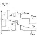
- FIG. 2 shows in a time-velocity diagram the progression of the threshold values with and without correction and of the integrated acceleration signal. It can be seen that the integrated acceleration value ⁇ v x is up to the time 17, both higher than the adjusted threshold value .DELTA.v XADD-ON and the signal output by the threshold value calculation 4 .DELTA.v threshold XTH. From this time 17, however, the integrated acceleration signal is below the corrected threshold, so that the comparator 15 does not output a drive signal for the restraint system. Without the correction by the subtractor 6, the integrated acceleration signal ⁇ v x would be above the threshold value ⁇ v XTH until the point in time 16. This showed that the signal analysis could avoid triggering.
Landscapes
- Engineering & Computer Science (AREA)
- Mechanical Engineering (AREA)
- Air Bags (AREA)
- Automotive Seat Belt Assembly (AREA)
Claims (9)
- Procédé de commande d'un système de retenue, selon lequel on génère un signal d'accélération caractéristique pour une collision, le signal d'accélération est d'une part intégré dans un signal de vitesse et d'autre part utilisé pour déterminer une valeur de seuil pour le signal de vitesse, la valeur de seuil est adaptée par une grandeur (ΔvVADD-ON) qui est déterminée à partir d'une pluralité de caractéristiques du signal d'accélération et/ou du signal de vitesse et/ou d'au moins un autre signal de capteur, et on commande le système de retenue en fonction d'une comparaison du signal de vitesse (Δvx) avec la valeur de seuil adaptée (ΔVXTH-ADD),
caractérisé en ce que
la pluralité de caractéristiques est déterminée en fonction d'un coup de marteau et/ou d'une fenêtre d'intégration et/ou d'un signal d'un capteur frontal et/ou en fonction d'une influence de signal par une barrière déformable et/ ou par une identification modèle. - Procédé selon la revendication 1,
caractérisé en ce que
la pluralité de caractéristiques est totalisée par un additionneur (8). - Procédé selon l'une quelconque des revendications 1 ou 2,
caractérisé en ce qu'
on utilise au moins un amplificateur (7) pour évaluer la grandeur. - Procédé selon la revendication 3,
caractérisé en ce que
l'amplificateur (7) est réglé de façon adaptative. - Procédé selon l'une quelconque des revendications précédentes,
caractérisé en ce qu'
un filtre (3) est utilisé pour le filtrage du signal d'accélération avant le calcul de la valeur de seuil (4). - Procédé selon l'une quelconque des revendications précédentes,
caractérisé en ce qu'
au moins une partie des caractéristiques et/ ou l'au moins un signal de capteur sont combinés logiquement les uns avec les autres pour déterminer la grandeur (ΔvADD-ON). - Procédé selon la revendication 6,
caractérisé en ce que
la combinaison est réalisée à l'aide d'une matrice. - Procédé selon la revendication 7,
caractérisé en ce que
dans la matrice on combine des caractéristiques dynamiques avec des caractéristiques statiques. - Utilisation d'un appareil de commande dans un procédé selon l'une quelconque des revendications 1 à 8.
Applications Claiming Priority (3)
| Application Number | Priority Date | Filing Date | Title |
|---|---|---|---|
| DE10227003A DE10227003A1 (de) | 2002-06-18 | 2002-06-18 | Verfahren zur Ansteuerung eines Rückhaltesystems |
| DE10227003 | 2002-06-18 | ||
| PCT/DE2003/000453 WO2003106226A1 (fr) | 2002-06-18 | 2003-02-14 | Procede de declenchement du fonctionnement d' un systeme de retenue |
Publications (2)
| Publication Number | Publication Date |
|---|---|
| EP1517815A1 EP1517815A1 (fr) | 2005-03-30 |
| EP1517815B1 true EP1517815B1 (fr) | 2007-02-14 |
Family
ID=29723208
Family Applications (1)
| Application Number | Title | Priority Date | Filing Date |
|---|---|---|---|
| EP03714639A Expired - Lifetime EP1517815B1 (fr) | 2002-06-18 | 2003-02-14 | Procede de declenchement du fonctionnement d' un systeme de retenue |
Country Status (6)
| Country | Link |
|---|---|
| US (1) | US20060085114A1 (fr) |
| EP (1) | EP1517815B1 (fr) |
| JP (1) | JP2005529786A (fr) |
| CN (1) | CN1688465A (fr) |
| DE (2) | DE10227003A1 (fr) |
| WO (1) | WO2003106226A1 (fr) |
Families Citing this family (10)
| Publication number | Priority date | Publication date | Assignee | Title |
|---|---|---|---|---|
| EP1678012B1 (fr) * | 2003-10-17 | 2007-12-19 | Volkswagen Aktiengesellschaft | Procede de fabrication d'un vehicule |
| DE10360769B4 (de) * | 2003-12-23 | 2012-04-12 | Conti Temic Microelectronic Gmbh | Verfahren und Vorrichtung zum Auslösen mindestens einer Insassenschutzeinrichtung in einem Fahrzeug |
| JP4614050B2 (ja) * | 2004-04-27 | 2011-01-19 | アイシン精機株式会社 | 車両の乗員保護装置 |
| US7477974B2 (en) * | 2004-07-27 | 2009-01-13 | Robert Bosch Gmbh | Vehicle restraint device control method and apparatus using dynamically determined threshold |
| CN101316742B (zh) | 2005-10-13 | 2011-02-09 | Trw汽车美国有限责任公司 | 控制车辆中的可致动约束系统的装置 |
| DE102006042769C5 (de) * | 2006-09-12 | 2011-07-28 | Continental Automotive GmbH, 30165 | Verfahren und Vorrichtung zum Auslösen eines Personenschutzmittels für ein Fahrzeug |
| DE102008008850A1 (de) | 2008-02-13 | 2009-08-20 | Robert Bosch Gmbh | Verfahren und Steuergerät zur Ansteuerung von Personenschutzmitteln für ein Fahrzeug |
| GB201105277D0 (en) * | 2011-03-29 | 2011-05-11 | Jaguar Cars | Speed and category trigger for an active device of a vehicle |
| DE102013208686B4 (de) | 2013-05-13 | 2024-02-08 | Robert Bosch Gmbh | Vorrichtung zur Ansteuerung von Personenschutzmitteln in einem Fahrzeug |
| DE102013212092B4 (de) | 2013-06-25 | 2024-01-25 | Robert Bosch Gmbh | Verfahren und Vorrichtung zum Betreiben einer Fußgängerschutzeinrichtung eines Fahrzeugs, Fußgängerschutzeinrichtung |
Family Cites Families (8)
| Publication number | Priority date | Publication date | Assignee | Title |
|---|---|---|---|---|
| DE4213673C2 (de) * | 1992-04-25 | 1994-09-08 | Dornier Gmbh | Auslöseverfahren für ein Rückhaltesystem |
| NL9201896A (nl) * | 1992-10-30 | 1994-05-16 | Fokker Aircraft | Bewegings-simulator. |
| DE4445996C2 (de) * | 1994-12-22 | 2002-10-24 | Bosch Gmbh Robert | Verfahren zur Auslösung von Rückhaltemitteln |
| DE19625004A1 (de) * | 1996-06-22 | 1998-01-08 | Daimler Benz Ag | Auslöseschaltung für ein Insassen-Rückhaltesystem |
| JP3044709B2 (ja) * | 1997-09-19 | 2000-05-22 | トヨタ自動車株式会社 | 乗員保護装置の起動制御装置 |
| DE19753971B4 (de) * | 1997-12-05 | 2009-11-26 | Robert Bosch Gmbh | Verfahren und Vorrichtung zur Steuerung einer Bremsanlage eines Fahrzeugs |
| US6549836B1 (en) * | 2000-06-07 | 2003-04-15 | Trw Inc. | Method and apparatus for controlling an actuatable restraint device using a velocity/displacement based safing function with immunity box |
| DE10065518B4 (de) * | 2000-12-28 | 2004-10-14 | Robert Bosch Gmbh | Verfahren zum Auslösen von Rückhaltemitteln in einem Kraftfahrzeug |
-
2002
- 2002-06-18 DE DE10227003A patent/DE10227003A1/de not_active Withdrawn
-
2003
- 2003-02-14 DE DE50306518T patent/DE50306518D1/de not_active Expired - Lifetime
- 2003-02-14 US US10/518,165 patent/US20060085114A1/en not_active Abandoned
- 2003-02-14 CN CNA038074060A patent/CN1688465A/zh active Pending
- 2003-02-14 WO PCT/DE2003/000453 patent/WO2003106226A1/fr active IP Right Grant
- 2003-02-14 JP JP2004513081A patent/JP2005529786A/ja active Pending
- 2003-02-14 EP EP03714639A patent/EP1517815B1/fr not_active Expired - Lifetime
Also Published As
| Publication number | Publication date |
|---|---|
| DE50306518D1 (de) | 2007-03-29 |
| DE10227003A1 (de) | 2004-01-15 |
| US20060085114A1 (en) | 2006-04-20 |
| WO2003106226A1 (fr) | 2003-12-24 |
| JP2005529786A (ja) | 2005-10-06 |
| CN1688465A (zh) | 2005-10-26 |
| EP1517815A1 (fr) | 2005-03-30 |
Similar Documents
| Publication | Publication Date | Title |
|---|---|---|
| EP1339572B1 (fr) | Procede et systeme de declenchement de moyens de retenue dans un vehicule | |
| EP1536992B1 (fr) | Procede pour commander un pretensionneur de ceinture a deux etages | |
| DE19945923B4 (de) | Verfahren und Vorrichtung zum Abfühlen von Seitenaufprallzusammenstoßzuständen mittels einer erhöhten Sicherungsfunktion | |
| DE19848997B4 (de) | Fahrzeuginsassenschutzsystem | |
| EP2318238B1 (fr) | Procédé et appareil de commande destinés à commander des moyens de protection des personnes pour un véhicule | |
| EP1380474B1 (fr) | Dispositif de contrôle de moyens de retenue | |
| EP0978425B1 (fr) | Méthode et appareil pour le déploiement d' au moins un airbag au moyen de capteurs sensibles à une pression excercée | |
| EP1160134B1 (fr) | Système de retenue de passager | |
| DE19938891B4 (de) | Verfahren und Vorrichtung zur Steuerung der Auslösung eines Kraftfahrzeug-Insassenschutzsystems | |
| EP1599363A1 (fr) | Procede d'activation de moyens de retenue | |
| DE10123921C1 (de) | Insassenrückhaltesystem mit einer Gurtkraftbegrenzungsvorrichtung | |
| EP1034985A2 (fr) | Méthode et dispositif de commande d'un système de retenue d' un véhicule | |
| WO2010142380A1 (fr) | Procédé de commande d'un dispositif de retenue pour occupants d'un véhicule | |
| EP1517815B1 (fr) | Procede de declenchement du fonctionnement d' un systeme de retenue | |
| WO2005061281A1 (fr) | Procede pour commander des moyens de protection de personnes | |
| EP2504200A1 (fr) | Appareil de commande destiné au réglage d'un dispositif permettant la dégradation adaptative de l'énergie de collision pour un véhicule, dispositif permettant la dégradation adaptative de l'énergie de collision pour un véhicule et procédé de réglage d'un dispositif permettant la dégradation adaptative de l'énergie de collision pour un véhicule | |
| EP2593337A1 (fr) | Procédé pour protéger un occupant d'un véhicule, module de commande pour commander un dispositif d'actionnement pour protéger un occupant d'un véhicule et système comprenant un tel module de commande et un dispositif d'actionnement correspondant | |
| EP1610981B1 (fr) | Dispositif pour commander des moyens de retenue dans un vehicule | |
| DE60206156T2 (de) | Vorrichtung zur aktivierung einer insassenschutzeinrichtung und verfahren zu dessen ansteuerung | |
| DE102009020074B4 (de) | Verfahren zur Ansteuerung von Kraftfahrzeuginsassen-Schutzsystemen | |
| WO2001044024A1 (fr) | Dispositif de retenue reglable, destine a des automobiles | |
| EP1551671B1 (fr) | Dispositif de commande d'un systeme de retenue | |
| EP2222511B1 (fr) | Procédé et appareil de commande pour commander des moyens de protection des personnes pour un véhicule | |
| EP1599366B1 (fr) | Procede pour declencher des moyens de retenue | |
| DE60306377T2 (de) | Kollisionspulsenergie-algorithmus für ein aufblasbares rückhaltesystem |
Legal Events
| Date | Code | Title | Description |
|---|---|---|---|
| PUAI | Public reference made under article 153(3) epc to a published international application that has entered the european phase |
Free format text: ORIGINAL CODE: 0009012 |
|
| 17P | Request for examination filed |
Effective date: 20050118 |
|
| AK | Designated contracting states |
Kind code of ref document: A1 Designated state(s): AT BE BG CH CY CZ DE DK EE ES FI FR GB GR HU IE IT LI LU MC NL PT SE SI SK TR |
|
| RBV | Designated contracting states (corrected) |
Designated state(s): DE FR GB IT |
|
| RIC1 | Information provided on ipc code assigned before grant |
Ipc: B60R 21/0132 20060101AFI20060622BHEP |
|
| GRAP | Despatch of communication of intention to grant a patent |
Free format text: ORIGINAL CODE: EPIDOSNIGR1 |
|
| GRAS | Grant fee paid |
Free format text: ORIGINAL CODE: EPIDOSNIGR3 |
|
| GRAA | (expected) grant |
Free format text: ORIGINAL CODE: 0009210 |
|
| AK | Designated contracting states |
Kind code of ref document: B1 Designated state(s): DE FR GB IT |
|
| REG | Reference to a national code |
Ref country code: GB Ref legal event code: FG4D Free format text: NOT ENGLISH |
|
| REF | Corresponds to: |
Ref document number: 50306518 Country of ref document: DE Date of ref document: 20070329 Kind code of ref document: P |
|
| GBT | Gb: translation of ep patent filed (gb section 77(6)(a)/1977) |
Effective date: 20070516 |
|
| ET | Fr: translation filed | ||
| PLBE | No opposition filed within time limit |
Free format text: ORIGINAL CODE: 0009261 |
|
| STAA | Information on the status of an ep patent application or granted ep patent |
Free format text: STATUS: NO OPPOSITION FILED WITHIN TIME LIMIT |
|
| 26N | No opposition filed |
Effective date: 20071115 |
|
| PG25 | Lapsed in a contracting state [announced via postgrant information from national office to epo] |
Ref country code: IT Free format text: LAPSE BECAUSE OF FAILURE TO SUBMIT A TRANSLATION OF THE DESCRIPTION OR TO PAY THE FEE WITHIN THE PRESCRIBED TIME-LIMIT Effective date: 20070214 |
|
| PGFP | Annual fee paid to national office [announced via postgrant information from national office to epo] |
Ref country code: FR Payment date: 20120228 Year of fee payment: 10 |
|
| PGFP | Annual fee paid to national office [announced via postgrant information from national office to epo] |
Ref country code: GB Payment date: 20120222 Year of fee payment: 10 |
|
| GBPC | Gb: european patent ceased through non-payment of renewal fee |
Effective date: 20130214 |
|
| REG | Reference to a national code |
Ref country code: FR Ref legal event code: ST Effective date: 20131031 |
|
| PG25 | Lapsed in a contracting state [announced via postgrant information from national office to epo] |
Ref country code: GB Free format text: LAPSE BECAUSE OF NON-PAYMENT OF DUE FEES Effective date: 20130214 Ref country code: FR Free format text: LAPSE BECAUSE OF NON-PAYMENT OF DUE FEES Effective date: 20130228 |
|
| PGFP | Annual fee paid to national office [announced via postgrant information from national office to epo] |
Ref country code: DE Payment date: 20140417 Year of fee payment: 12 |
|
| REG | Reference to a national code |
Ref country code: DE Ref legal event code: R119 Ref document number: 50306518 Country of ref document: DE |
|
| PG25 | Lapsed in a contracting state [announced via postgrant information from national office to epo] |
Ref country code: DE Free format text: LAPSE BECAUSE OF NON-PAYMENT OF DUE FEES Effective date: 20150901 |