EP1517477B1 - Sendeleistungssteuerung für Funknetze mit Direkt-Übertragung zwischen mobilen Endgeräten - Google Patents
Sendeleistungssteuerung für Funknetze mit Direkt-Übertragung zwischen mobilen Endgeräten Download PDFInfo
- Publication number
- EP1517477B1 EP1517477B1 EP04030317A EP04030317A EP1517477B1 EP 1517477 B1 EP1517477 B1 EP 1517477B1 EP 04030317 A EP04030317 A EP 04030317A EP 04030317 A EP04030317 A EP 04030317A EP 1517477 B1 EP1517477 B1 EP 1517477B1
- Authority
- EP
- European Patent Office
- Prior art keywords
- wireless device
- accordance
- wireless
- measurement results
- central
- Prior art date
- Legal status (The legal status is an assumption and is not a legal conclusion. Google has not performed a legal analysis and makes no representation as to the accuracy of the status listed.)
- Expired - Lifetime
Links
Images

Classifications
-
- H—ELECTRICITY
- H04—ELECTRIC COMMUNICATION TECHNIQUE
- H04W—WIRELESS COMMUNICATION NETWORKS
- H04W52/00—Power management, e.g. Transmission Power Control [TPC] or power classes
- H04W52/04—Transmission power control [TPC]
- H04W52/18—TPC being performed according to specific parameters
- H04W52/24—TPC being performed according to specific parameters using SIR [Signal to Interference Ratio] or other wireless path parameters
- H04W52/247—TPC being performed according to specific parameters using SIR [Signal to Interference Ratio] or other wireless path parameters where the output power of a terminal is based on a path parameter sent by another terminal
-
- H—ELECTRICITY
- H04—ELECTRIC COMMUNICATION TECHNIQUE
- H04B—TRANSMISSION
- H04B17/00—Monitoring; Testing
- H04B17/20—Monitoring; Testing of receivers
- H04B17/24—Monitoring; Testing of receivers with feedback of measurements to the transmitter
-
- H—ELECTRICITY
- H04—ELECTRIC COMMUNICATION TECHNIQUE
- H04B—TRANSMISSION
- H04B17/00—Monitoring; Testing
- H04B17/30—Monitoring; Testing of propagation channels
- H04B17/309—Measuring or estimating channel quality parameters
-
- H—ELECTRICITY
- H04—ELECTRIC COMMUNICATION TECHNIQUE
- H04B—TRANSMISSION
- H04B17/00—Monitoring; Testing
- H04B17/30—Monitoring; Testing of propagation channels
- H04B17/391—Modelling the propagation channel
-
- H—ELECTRICITY
- H04—ELECTRIC COMMUNICATION TECHNIQUE
- H04L—TRANSMISSION OF DIGITAL INFORMATION, e.g. TELEGRAPHIC COMMUNICATION
- H04L12/00—Data switching networks
- H04L12/28—Data switching networks characterised by path configuration, e.g. LAN [Local Area Networks] or WAN [Wide Area Networks]
- H04L12/40—Bus networks
- H04L12/40052—High-speed IEEE 1394 serial bus
- H04L12/40078—Bus configuration
-
- H—ELECTRICITY
- H04—ELECTRIC COMMUNICATION TECHNIQUE
- H04L—TRANSMISSION OF DIGITAL INFORMATION, e.g. TELEGRAPHIC COMMUNICATION
- H04L41/00—Arrangements for maintenance, administration or management of data switching networks, e.g. of packet switching networks
- H04L41/12—Discovery or management of network topologies
-
- H—ELECTRICITY
- H04—ELECTRIC COMMUNICATION TECHNIQUE
- H04L—TRANSMISSION OF DIGITAL INFORMATION, e.g. TELEGRAPHIC COMMUNICATION
- H04L45/00—Routing or path finding of packets in data switching networks
- H04L45/42—Centralised routing
-
- H—ELECTRICITY
- H04—ELECTRIC COMMUNICATION TECHNIQUE
- H04W—WIRELESS COMMUNICATION NETWORKS
- H04W16/00—Network planning, e.g. coverage or traffic planning tools; Network deployment, e.g. resource partitioning or cells structures
- H04W16/18—Network planning tools
-
- H—ELECTRICITY
- H04—ELECTRIC COMMUNICATION TECHNIQUE
- H04W—WIRELESS COMMUNICATION NETWORKS
- H04W52/00—Power management, e.g. Transmission Power Control [TPC] or power classes
- H04W52/04—Transmission power control [TPC]
- H04W52/18—TPC being performed according to specific parameters
- H04W52/24—TPC being performed according to specific parameters using SIR [Signal to Interference Ratio] or other wireless path parameters
- H04W52/245—TPC being performed according to specific parameters using SIR [Signal to Interference Ratio] or other wireless path parameters taking into account received signal strength
-
- H—ELECTRICITY
- H04—ELECTRIC COMMUNICATION TECHNIQUE
- H04W—WIRELESS COMMUNICATION NETWORKS
- H04W52/00—Power management, e.g. Transmission Power Control [TPC] or power classes
- H04W52/04—Transmission power control [TPC]
- H04W52/38—TPC being performed in particular situations
- H04W52/386—TPC being performed in particular situations centralized, e.g. when the radio network controller or equivalent takes part in the power control
-
- H—ELECTRICITY
- H04—ELECTRIC COMMUNICATION TECHNIQUE
- H04W—WIRELESS COMMUNICATION NETWORKS
- H04W24/00—Supervisory, monitoring or testing arrangements
- H04W24/08—Testing, supervising or monitoring using real traffic
Definitions
- the present invention relates to the transmission power control for wireless networks with direct mode traffic.
- a typical wireless network such as the IEEE 1394 based HIPERLAN type 2 broadband radio access network which specification is developed by ETSI is shown in Fig. 3.
- An access point or central controller 15 has an up- and downlink communication with several mobile terminals 11, 12, 13, and 14 and the mobile terminals can also have a direct communication in-between each other so that apart from the granting of resources for peer mobile terminals, e. g. the first mobile terminal 11 and the second mobile terminal 12, the access point or central controller 15 is not involved in the communication.
- Such direct communications in-between two or more mobile terminals are called direct mode.
- An IEEE 1394 bus with connected network devices is exemplary shown only for the fourth mobile terminal 14.
- the problem in wireless networks including direct mode traffic is that the mobile terminals do not know with which other devices they have radio link. Thus, they intend to request the central controller 15 to set up certain connections even though they are not possible.
- a second problem is the transmit power control during direct mode traffic. Without knowledge about the radio link quality always maximum transmit power levels have to be used until appropriate levels are identified.
- a topology map has been introduced indicating the quality of connectivity of each network device of a wireless network with all other network devices in said wireless network. After distribution of this topology map, a mobile terminal can check whether a connection is possible or not before requesting it with the central controller. Furtheron, transmit power control can be performed using an initial power level determined on the quality of connectivity of the particular radio link.
- the central controller can inform the peer wireless devices to set up their transmit power levels accordingly until accurate transmit power control is performed.
- EP 0 695 059 discloses an internetworking node for providing internetworking services for mobile wireless nodes.
- Each mobile wireless node is registered with at most one internetworking node.
- Each mobile wireless node emits a topology broadcast identifying itself and other nodes it has heard.
- Each internetworking node uses these topology broadcasts to construct a table tracking each mobile node within its range, whether that mobile node is registered to that internetworking node and also a list of which other nodes that mobile wireless node can hear.
- the internetworking node determines which of these wireless nodes it will register.
- the internetworking node will then act for all wireless nodes registered to it in relaying messages between wireless nodes or between a wired LAN and the wireless nodes.
- US patent 5,862,477 teaches a topology verification process for controlling a Personal Communication Services (PCS) system which includes a plurality of Cordless Fixed Parts (CFP)s.
- the process includes mapping the spatial relationships of the CFPs utilizing Received Signal Strength Indication (RSSI) vectors resulting from test signals transmitted between the CFPs, to establish the topology of the system; repeating the mapping process after any disruption of power to the system, and comparing the results. Any significant change in the results, would be highly indicative of a potential change in the geographic area of operation of the system, and can be used to initiate disablement of the system operation. Additional confirmation that the system has not been reconfigured (and hence moved), may be had by matching a unique identifier for each CFP against a stored set of identifiers which specify the particular port that the CFP was connected to immediately prior to any disruption in power to the system.
- RSSI Received Signal Strength Indication
- the present invention provides a method for operating a wireless network in accordance with independent claim 1 or 2 as well as a wireless device for operation in a wireless network in accordance with independent claim 21.
- Preferred embodiments of the invention are reflected in the dependent claims.
- a method to create a topology map indicating the quality of connectivity of each network device of a wireless network with all other network devices in said wireless network comprises the following steps: performing a measurement phase in which a calibration signal is successively broadcasted by each network device and in which all respective other network devices receiving said calibration signal measure the received signal quality; performing a reporting phase in which the measurement results are transmitted from each network device to the network device creating said topology map; and performing a creating phase in which said topology map of the network is created within the network device creating said topology map on basis of all received measurement results.
- a very quick creation of the topology map is possible, since no bandwidth is wasted transmitting small amounts of data, namely single measurement results, from the network devices that have measured the received signal quality of one control signal to the network device creating said topology map, but since first all measurement results are collected before they are transmitted to the network device creating the topology map.
- said measurement phase and/or said reporting phase are initiated by the network device creating the topology map.
- the topology map is updated when a new network device joins the network and/or after a predetermined amount of time has lapsed.
- a first type of network device for a wireless network is characterized by means to broadcast a calibration signal, to measure a power level of a received calibration signal, and to transmit its measurement results to another network device or to store it internally.
- the network device preferably comprises a decoder that initiates the broadcast of a control signal and the measurement of the reception quality of one or more incoming broadcast signals upon reception of a measurement control signal and that further preferably initiates the transmission of one or more measurement results upon reception of a reporting control signal.
- the network device is characterized by a report encoder that receives one or more signal quality indication signals and encodes therefrom a signal quality control signal to be transmitted to said other network device or to be stored internally.
- a second type of network device is characterized by means to initiate a measurement phase, to initiate a reporting phase, and to perform a creation of a topology map on basis of measurement results received during the reporting phase.
- This second type of network device preferably includes all features of the first type of network device according to the above, preferred embodiment.
- the first type of network device is either a mobile terminal or a mobile terminal having the functionality of a central controller, whereas the second type of network device according to the present invention always has the functionality of a central controller.
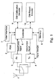
- the mobile terminal shown in Fig. 1 is adapted to perform a direct mode calibration according to a preferred embodiment.
- the shown mobile terminal has one antenna 1 which is connected to the movable terminal of a transmit/receive selection switch 2 which fixed terminals are respectively connected to the transmitter and receiver signal path of the mobile terminal.
- a receiver 3 is directly connected to the respective fixed terminal of the transmit/receive selection switch 2.
- This receiver 3 produces a data and control signal input to a controller 6 and also outputs a signal wherefrom a signal quality measurement unit 5 can determine the received signal strength which is output to the controller 6.
- the controller 6 For the transmitter signal path the controller 6 outputs a data and control signal to a transmitter 4 which modulates, up-converts and amplifies this signal to a given signal strength which is indicated to the transmitter 4 by a control signal generated by the controller 6 and outputs the generated transmission signal to the respective fixed terminal of the transmit/receive selection switch 2.
- a control signal generated by the controller 6 Bi-directionally connected to the controller are a user interface 7 and a memory 8. Furtheron, the controller 6 is connected to a direct mode calibration decoder 9 and a direct mode report encoder 10.
- the direct mode calibration decoder 9 receives the control signals generated by the receiver 3 via the controller 6 and initiates the broadcast of a calibration signal and the measurement of the reception quality of one or more incoming broadcasted calibration signals from other mobile terminals upon reception of a measurement control signal which is transmitted from the central controller 15. Furtheron, upon reception of a reporting control signal which is also transmitted from the central controller 15 the direct mode calibration decoder 9 initiates the transmission of one or more measurement results to said central controller 15. Therefore, all measurement results stored within the memory 8 are communicated to the direct mode report encoder 10 by the controller 6 and said direct mode report encoder 10 generates a signal quality control signal that is transmitted via the controller 6 and the transmitter 4 to the central controller 15. The central controller 15 creates a topology map on basis of all measurement results received from all mobile terminals during the reporting phase.
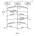
- Fig. 2 shows the messaging in-between the central controller 15 having a medium access control identifier, i. e. MAC-ID3, and a first mobile terminal 11 having a MAC-ID1 and a second mobile terminal 12 having a MAC-ID2, after the calibration procedure is decided to be started, since either a new mobile terminal joins the network or a timer has expired.
- a medium access control identifier i. e. MAC-ID3
- a first mobile terminal 11 having a MAC-ID1
- a second mobile terminal 12 having a MAC-ID2
- a first step S1 the central controller 15 send measurement control signals to both mobile terminals 11 and 12.
- the central controller 15 itself knows that the measurement phase of the calibration procedure will be performed. Therefore, after the first step S1 all three network devices, namely the central controller 15 and the first and second mobile terminals 11 and 12, are initialized to perform the measurement phase.
- all network devices within the wireless network successively broadcast a calibration signal and receive the calibration signals transmitted by the other network devices to determine their respective signal quality. Therefore, in a step S2 the first mobile terminal 11 broadcasts its calibration signal to the central controller 15 and the second mobile terminal 12 which receive said calibration signal, measure its signal quality, and store it in an internal memory.
- the central controller 15 itself performs the broadcast of a calibration signal to the first and second mobile terminals 11 and 12 in a step S3. Both mobile terminals 11 and 12 respectively receive the calibration signal, measure its signal quality and store this value in an internal memory. Following in a step S4 the second mobile terminal 12 also broadcasts a calibration signal to the first mobile terminal 11 and the central controller 15 which respectively receive this calibration signal, measure its signal quality and store this measured value in an internal memory. After all mobile terminals have broadcasted their calibration signals and these calibration signals are received and measured by all respective other devices, the central controller 15 transmits a reporting control signal in a step S5 to the first mobile terminal 11 and the second mobile terminal 12.
- both mobile terminals After reception of the reporting control signal, both mobile terminals generate a signal quality control signal comprising one or more measurement results and transmit it respectively to the central controller 15.
- the first mobile terminal 11 transmits its signal quality control signal in a step S6 to the central controller 15 and the second mobile terminal 12 transmits its signal quality control signal to the central controller 15 in a step S7.
- the central controller 15 knows its own measurement results, since they are already stored in its internal memory. Upon reception of all measurement results from all other mobile terminals within the network, the central controller 15 generates the topology map which indicates the reception quality for every radio link available within the network.
- the calibration procedure mainly consists of two phases, namely the measurement phase and the reporting phase.
- the calibration slot is transmitted using a dedicated control channel. It contains the source identifier.
- the calibration slot is transmitted using the maximum allowed transmit power level in order to avoid artificial hidden nodes.
- Each other wireless device measures the received quality, e. g. by means of the received signal strength and stores it in an internal memory.
- each wireless device reports its measurement results to the central controller using a dedicated control channel.
- the report slot contains the identifier of the wireless device and the report measurements.
- One or more measurement results can be transmitted in one report slot.
- the central controller (in a third phase) creates a topology map of the network which indicates the quality of connectivity of each wireless device with all others.
- a possible topology map of a network with n active devis represented into a matrix is shown below:
- RSS n-m represents the received signal strength at mobile terminal n when transmitted by mobile terminal m.
- the central controller is also regarded as mobile terminal, since in a wireless network environment with mobile terminals the task of the central controller might be switched from one mobile terminal to another.
- 4 bits are used to map the received signal quality, i. e. the received power to a signal strength code. Therefore, there exist sixteen possibilities of designated received power levels to be included in the topology map.
- a bandwidth of ⁇ -90 dBm to > -30dBm is set with a step size of 3 dB and a range of -69 dBm to -48 dBm as a medium range mapped to one coding value.
- mapping e. g. in a strictly linear or non-linear fashion can be performed as well.
- An update of the topology map is always triggered by the central controller. It is started as a high priority calibration when a new mobile terminal joins the network so that an updated topology map is nearly immediately created, e. g. within 2 ms. Furtheron, a low priority calibration is started every time when a timer expires, e. g. every 100 ms. Low priority in this sense means that the calibration is carried out every time free resources are available.
- the topology map of the network might be broadcast by the central controller to all mobile terminals and depending on the used system it might be transmitted as a whole or line by line.
- a mobile terminal receiving the topology map preferably stores this topology map together with a time stamp.
- Another possibility to give knowledge about the network topology to a mobile terminal is to just transmit a particular line or value of the topology map to the corresponding network device.
- the present invention is not only to be used with an IEEE 1394 based HIPERLAN type 2 network, but with any wireless network, preferably with such supporting direct mode.
Landscapes
- Engineering & Computer Science (AREA)
- Computer Networks & Wireless Communication (AREA)
- Signal Processing (AREA)
- Physics & Mathematics (AREA)
- Electromagnetism (AREA)
- Quality & Reliability (AREA)
- Mobile Radio Communication Systems (AREA)
- Maintenance And Management Of Digital Transmission (AREA)
- Monitoring And Testing Of Transmission In General (AREA)
- Small-Scale Networks (AREA)
Claims (32)
- Verfahren zum Durchführen einer Sendeleistungssteuerung in einem drahtlosen Netzwerk mit einer Mehrzahl drahtloser Geräte und einem zentralen drahtlosen Gerät (15), wobei das Verfahren die Schritte aufweist:Empfangen eines Messungs-Steuersignals vom zentralen drahtlosen Gerät in einem oder mehreren der Mehrzahl drahtloser Geräte;Erstellen von Messergebnissen in einem oder mehreren der drahtlosen Geräte, welche die Qualität der direkten Kommunikation zwischen den drahtlosen Geräten des drahtlosen Netzwerks kennzeichnen; undBerichten der Messergebnisse an das zentrale drahtlose Gerät zur Steuerung einer Sendeleistung, wobei
der Erstellungsschritt ein Erstellen von Messergebnissen durch Übertragen von Signalen und Messen der Qualität der empfangenen Signale beinhaltet, wobei die Messergebnisse die Qualität der direkten Kommunikation zwischen einem der Mehrzahl drahtloser Geräte und einem weiteren der Mehrzahl drahtloser Geräte kennzeichnen. - Verfahren zum Durchführen einer Sendeleistungssteuerung in einem drahtlosen Netzwerk mit einer Mehrzahl drahtloser Geräte und einem zentralen drahtlosen Gerät (15), wobei das Verfahren die Schritte aufweist:Senden eines Messungs-Steuersignals von dem zentralen drahtlosen Gerät;Empfangen eines Messungs-Steuersignals vom zentralen drahtlosen Gerät in einem oder mehreren der Mehrzahl drahtloser Geräte;Erstellen von Messergebnissen in einem oder mehreren der drahtlosen Geräte, welche die Qualität der direkten Kommunikation zwischen den drahtlosen Geräten des drahtlosen Netzwerks kennzeichnen; undBerichten der Messergebnisse an das zentrale drahtlose Gerät zur Steuerung einer Sendeleistung, wobei
der Erstellungsschritt ein Erstellen von Messergebnissen durch Übertragen von Signalen und Messen der Qualität der empfangenen Signale beinhaltet, wobei die Messergebnisse die Qualität der direkten Kommunikation zwischen einem der Mehrzahl drahtloser Geräte und einem weiteren der Mehrzahl drahtloser Geräte kennzeichnen. - Verfahren nach Anspruch 1 oder 2, wobei die Messergebnisse in Erwiderung auf das Messungs-Steuersignal erstellt werden.
- Verfahren nach einem der vorangehenden Ansprüche, wobei die Messergebnisse in Erwiderung auf das Messungs-Steuersignal berichtet werden.
- Verfahren nach einem der vorangehenden Ansprüche, wobei die Messergebnisse in einem drahtlosen Gerät des drahtlosen Netzwerks, welches das Messungs-Steuersignal empfangen hat, erstellt werden.
- Verfahren nach einem der vorangehenden Ansprüche, wobei das zentrale drahtlose Gerät ein Zugangspunkt (15) oder Zentral-Controller (15) ist.
- Verfahren nach einem der vorangehenden Ansprüche, wobei das drahtlose Netzwerk ein oder mehrere mobile Stationen (11, 12, 13, 14) als drahtlose Geräte des drahtlosen Netzwerks aufweist.
- Verfahren nach einem der vorangehenden Ansprüche, wobei das drahtlose Netzwerk zum Ausführen einer Aufwärtslink- und Abwärtslink-Kommunikation zwischen dem zentralen drahtlosen Gerät und einer oder mehrerer der mobilen Stationen ausgelegt und geeignet ist und die direkte Kommunikation eine solche Aufwärtslink-/Abwärtslink-Kommunikation beinhaltet.
- Verfahren nach einem der vorangehenden Ansprüche, wobei das drahtlose Netzwerk zum Ausführen einer Direktmodus-Kommunikation zwischen zwei oder mehreren der mobilen Stationen ausgelegt und geeignet ist und die direkte Kommunikation eine derartige Direktmodus-Kommunikation beinhaltet.
- Verfahren nach einem der vorangehenden Ansprüche, wobei das drahtlose Netzwerk zum Ausführen einer direkten Kommunikation zwischen Beliebigen der drahtlosen Geräte des drahtlosen Netzwerks ausgelegt und geeignet ist.
- Verfahren nach Anspruch 10 mit dem Schritt:Empfangen von Steuerdaten vom zentralen drahtlosen Gerät in einem drahtlosen Gerät des Netzwerks zum Steuern der Sendeleistung, mit der das drahtlose Gerät die direkte Kommunikation ausführt.
- Verfahren nach Anspruch 11, wobei die Steuerdaten von dem zentralen drahtlosen Gerät gemäß den Messergebnissen erzeugt werden.
- Verfahren nach einem der vorangehenden Ansprüche mit dem Schritt:Erzeugen der Steuerdaten im zentralen drahtlosen Gerät gemäß den Messergebnissen.
- Verfahren nach einem der vorangehenden Ansprüche, wobei das zentrale drahtlose Gerät die direkte Kommunikation unterstützt.
- Verfahren nach einem der vorangehenden Ansprüche, wobei das zentrale drahtlose Gerät die direkte Kommunikation steuert.
- Verfahren nach Anspruch 14 oder 15, wobei das Unterstützen/Steuern ein Bewilligen von Ressourcen für Peer-Mobilstationen des drahtlosen Netzwerks und/oder Annehmen oder Verweigern einer Verbindungsanforderung zwischen zwei drahtlosen Geräten in Abhängigkeit von der Qualität der Funkverbindung und/oder Informieren der drahtlosen Peer-Geräte zur entsprechenden Festlegung deren Sendeleistungspegel, bis eine genaue Sendeleistungssteuerung durchgeführt wurde, umfasst.
- Verfahren nach einem der vorangehenden Ansprüche, wobei die Messergebnisse in Einheiten von dBm sind.
- Verfahren nach einem der vorangehenden Ansprüche, wobei das zentrale drahtlose Gerät Kommunikationsressourcen in Erwiderung auf eine Verbindungsanforderung von beliebigen weiteren der drahtlosen Geräte bewilligt oder ablehnt.
- Verfahren gemäß einem der vorangehenden Ansprüche, wobei die Messergebnisse in einem bestimmten Steuerkanal berichtet werden.
- Drahtloses Gerät zum Durchführen einer Sendeleistungskontrolle in einem drahtlosen Netzwerk mit einer Mehrzahl von drahtlosen Geräten sowie einem zentralen drahtlosen Gerät (15), wobei das Gerät aufweist:Einrichtung zum Empfangen eines Messungs-Steuersignals vom zentralen drahtlosen Gerät;Einrichtung zum Erstellen von Messergebnissen, welche die Qualität der direkten Kommunikation zwischen dem drahtlosen Gerät und einem oder mehreren der Mehrzahl drahtloser Geräte kennzeichnen; undEinrichtung zum Berichten der Messergebnisse an das zentrale drahtlose Gerät zur Steuerung einer Sendeleistung, wobei
die Messergebnisse die Qualität der direkten Kommunikation zwischen dem drahtlosen Gerät und einem der Mehrzahl drahtloser Geräte kennzeichnen und durch Übertragen von Signalen und Messen der Qualität der empfangenen Signale erhalten werden. - Drahtloses Gerät nach Anspruch 20, wobei die Erstellungseinrichtung zum Erstellen der Messergebnisse in Erwiderung auf das Messungs-Steuersignal ausgelegt und geeignet ist.
- Drahtloses Gerät gemäß Anspruch 20 oder 21, wobei die Berichteinrichtung zum Berichten der Messergebnisse in Erwiderung auf das Messungs-Steuersignal ausgelegt und geeignet ist.
- Drahtloses Gerät nach einem der Ansprüche 20-22, wobei das zentrale drahtlose Gerät ein Zugangspunkt (15) oder ein Zentral-Controller (15) ist.
- Drahtloses Gerät nach einem der Ansprüche 20-23, wobei das drahtlose Gerät eine mobile Station (11, 12, 13, 14) ist.
- Drahtloses Gerät nach einem der Ansprüche 20-24, wobei das drahtlose Gerät zum Ausführen einer Aufwärtslink- und Abwärtslink-Kommunikation mit dem zentralen drahtlosen Gerät ausgelegt und geeignet ist und die direkte Kommunikation eine solche Aufwärtslink-/Abwärtslink-Kommunikation beinhaltet.
- Drahtloses Gerät nach einem der Ansprüche 20-25, wobei das drahtlose Gerät zum Ausführen einer Direktmodus-Kommunikation mit mobilen Stationen ausgelegt und geeignet ist und die direkte Kommunikation eine derartige Direktmodus-Kommunikation beinhaltet.
- Drahtloses Gerät nach einem der Ansprüche 20-25 mit:einer Einrichtung zum Empfangen von Steuerdaten von dem zentralen drahtlosen Gerät zum Steuern einer Sendeleistung mit der das drahtlose Gerät eine direkte Kommunikation mit weiteren drahtlosen Geräten des drahtlosen Netzwerks ausführt.
- Drahtloses Gerät nach einem der Ansprüche 20-27 mit:einer Einrichtung zum Einstellen des Sendeleistungspegels des drahtlosen Geräts basierend auf Information von dem zentralen drahtlosen Gerät.
- Drahtloses Gerät nach einem der Ansprüche 20-28 mit:einem Direktmodus-Bericht-Encoder (10) zum Erzeugen eines Signalqualitätsteuersignals zur Übertragung an das zentrale drahtlose Gerät in Form des Messergebnisses.
- Drahtloses Gerät nach einem der Ansprüche 20-29 mit:einer Einrichtung zum Einstellen eines Sendeleistungspegels des drahtlosen Geräts basierend auf Information vom zentralen drahtlosen Gerät.
- Drahtloses Gerät nach einem der Ansprüche 20-30, wobei die Messergebnisse in Einheiten von dBm sind.
- Drahtloses Gerät nach einem der Ansprüche 20-31, wobei die Messergebnisse in einem bestimmten Steuerkanal berichtet werden.
Priority Applications (2)
| Application Number | Priority Date | Filing Date | Title |
|---|---|---|---|
| DE69935023T DE69935023T2 (de) | 1999-06-23 | 1999-06-23 | Sendeleistungssteuerung für Funknetze mit Direkt-Übertragung zwischen mobilen Endgeräten |
| EP04030317A EP1517477B1 (de) | 1999-06-23 | 1999-06-23 | Sendeleistungssteuerung für Funknetze mit Direkt-Übertragung zwischen mobilen Endgeräten |
Applications Claiming Priority (2)
| Application Number | Priority Date | Filing Date | Title |
|---|---|---|---|
| EP04030317A EP1517477B1 (de) | 1999-06-23 | 1999-06-23 | Sendeleistungssteuerung für Funknetze mit Direkt-Übertragung zwischen mobilen Endgeräten |
| EP99112129A EP1063819B1 (de) | 1999-06-23 | 1999-06-23 | Kalibrierungsverfahren für drahtlose Netze mit Direktverkehr |
Related Parent Applications (2)
| Application Number | Title | Priority Date | Filing Date |
|---|---|---|---|
| EP99112129A Division EP1063819B1 (de) | 1999-06-23 | 1999-06-23 | Kalibrierungsverfahren für drahtlose Netze mit Direktverkehr |
| EP99112129.4 Division | 1999-06-23 |
Publications (3)
| Publication Number | Publication Date |
|---|---|
| EP1517477A2 EP1517477A2 (de) | 2005-03-23 |
| EP1517477A3 EP1517477A3 (de) | 2005-03-30 |
| EP1517477B1 true EP1517477B1 (de) | 2007-01-24 |
Family
ID=8238408
Family Applications (2)
| Application Number | Title | Priority Date | Filing Date |
|---|---|---|---|
| EP04030317A Expired - Lifetime EP1517477B1 (de) | 1999-06-23 | 1999-06-23 | Sendeleistungssteuerung für Funknetze mit Direkt-Übertragung zwischen mobilen Endgeräten |
| EP99112129A Expired - Lifetime EP1063819B1 (de) | 1999-06-23 | 1999-06-23 | Kalibrierungsverfahren für drahtlose Netze mit Direktverkehr |
Family Applications After (1)
| Application Number | Title | Priority Date | Filing Date |
|---|---|---|---|
| EP99112129A Expired - Lifetime EP1063819B1 (de) | 1999-06-23 | 1999-06-23 | Kalibrierungsverfahren für drahtlose Netze mit Direktverkehr |
Country Status (4)
| Country | Link |
|---|---|
| US (2) | US7580711B1 (de) |
| EP (2) | EP1517477B1 (de) |
| JP (1) | JP2001057584A (de) |
| DE (1) | DE69922797T2 (de) |
Families Citing this family (26)
| Publication number | Priority date | Publication date | Assignee | Title |
|---|---|---|---|---|
| JP3349485B2 (ja) * | 1999-11-29 | 2002-11-25 | シャープ株式会社 | 無線通信装置及び無線通信方法 |
| US6795407B2 (en) * | 2000-04-22 | 2004-09-21 | Atheros Communications, Inc. | Methods for controlling shared access to wireless transmission systems and increasing throughput of the same |
| US6985465B2 (en) * | 2000-07-07 | 2006-01-10 | Koninklijke Philips Electronics N.V. | Dynamic channel selection scheme for IEEE 802.11 WLANs |
| US8676921B1 (en) * | 2000-10-03 | 2014-03-18 | Nokia Corporation | Contextual mapping based learning by converting information |
| US20060063503A1 (en) * | 2002-06-17 | 2006-03-23 | Koninklikle Phillips Electronics Nv | Receiver and tuner with electronically tuned filter |
| EP1550274B1 (de) * | 2002-10-11 | 2007-03-07 | Nokia Corporation | Dynamisches peer tunneling mit leistungsoptimierung |
| ES2260651T3 (es) * | 2002-10-29 | 2006-11-01 | Telefonaktiebolaget Lm Ericsson (Publ) | Generacion de informes para servicios multiusuario en redes inalambricas. |
| GB2396775B (en) | 2002-12-23 | 2005-04-13 | Motorola Inc | Method and apparatus for establishing direct communication for mobiles in a radio communication system |
| DE10354943B4 (de) * | 2003-11-25 | 2008-08-28 | Siemens Ag | Verfahren zum Betrieb einer Kommunikationsstrecke zwischen zumindest zwei Kommunikatonsendgeräten |
| US7430189B2 (en) | 2004-12-31 | 2008-09-30 | Lucent Technologies Inc. | Methods and devices for determining the adjacency of access points in a wireless network |
| GB0505633D0 (en) | 2005-03-18 | 2005-04-27 | Nokia Corp | Network optimisation |
| US8364185B2 (en) * | 2005-04-18 | 2013-01-29 | Samsung Electronics Co., Ltd. | Method and system for synchronizing a clock for an adjacent network to a clock for an overlay network |
| US7437127B2 (en) | 2005-07-28 | 2008-10-14 | Symbol Technologies, Inc. | Method and system for determining existence of a predetermined wireless network coverage condition in a wireless network |
| US8363594B2 (en) | 2006-11-08 | 2013-01-29 | Apple, Inc. | Address spoofing prevention |
| KR100969757B1 (ko) * | 2007-07-09 | 2010-07-13 | 삼성전자주식회사 | 통신 시스템에서 피어 투 피어 통신 방법 및 시스템 |
| JP5103324B2 (ja) * | 2008-08-18 | 2012-12-19 | 一般財団法人電力中央研究所 | 無線センサネットワークのセンサ端末配置支援方法及びプログラム |
| US20100203862A1 (en) * | 2009-02-09 | 2010-08-12 | Friedlander Gil | Method and a system for controlling and tracking radiation emitted from mobile phones |
| KR101576758B1 (ko) * | 2011-09-30 | 2015-12-10 | 텔레호낙티에볼라게트 엘엠 에릭슨(피유비엘) | 근본 원인 분석을 위한 방법, 장치, 및 통신 네트워크 |
| US8934378B1 (en) * | 2012-09-30 | 2015-01-13 | Emc Corporation | Resilient cache-based topology detection of a dynamic cluster |
| US9178769B2 (en) * | 2013-01-08 | 2015-11-03 | Comcast Cable Communication, Llc | Generation and management of network connectivity information |
| EP2876770B1 (de) * | 2013-11-22 | 2016-08-17 | TOSHIBA Electronics Europe GmbH | Verfahren zur kabellosen Übertragung einer Leistung |
| TWI551179B (zh) * | 2014-12-25 | 2016-09-21 | 台達電子工業股份有限公司 | 無線節點的自組織網路建立方法 |
| GB201701592D0 (en) | 2017-01-31 | 2017-03-15 | Nchain Holdings Ltd | Computer-implemented system and method |
| US11778021B2 (en) | 2017-01-31 | 2023-10-03 | Nchain Licensing Ag | Computer-implemented system and method for updating a network's knowledge of the network's topology |
| US12125246B2 (en) * | 2020-06-03 | 2024-10-22 | Labsphere, Inc. | Calibration network systems and methods of using the same |
| US11785490B2 (en) * | 2020-06-22 | 2023-10-10 | Qualcomm Incorporated | Configuring measurement gaps for network-assisted calibration procedures and/or performing network-assisted calibration procedures using serving beams |
Family Cites Families (30)
| Publication number | Priority date | Publication date | Assignee | Title |
|---|---|---|---|---|
| US5003619A (en) * | 1989-01-31 | 1991-03-26 | Motorola, Inc. | Method and apparatus for adjusting the power of a transmitter |
| US5546540A (en) * | 1991-01-14 | 1996-08-13 | Concord Communications, Inc. | Automatic topology monitor for multi-segment local area network |
| JP2921341B2 (ja) * | 1993-07-01 | 1999-07-19 | 三菱電機株式会社 | 通信システム |
| JPH0730483A (ja) * | 1993-07-13 | 1995-01-31 | Matsushita Electric Ind Co Ltd | 無線電話装置 |
| US5374936A (en) * | 1994-02-28 | 1994-12-20 | Feng; Jun | Security system |
| US5430729A (en) * | 1994-04-04 | 1995-07-04 | Motorola, Inc. | Method and apparatus for adaptive directed route randomization and distribution in a richly connected communication network |
| FI96468C (fi) * | 1994-05-11 | 1996-06-25 | Nokia Mobile Phones Ltd | Liikkuvan radioaseman kanavanvaihdon ohjaaminen ja lähetystehon säätäminen radiotietoliikennejärjestelmässä |
| CA2129199C (en) * | 1994-07-29 | 1999-07-20 | Roger Y.M. Cheung | Method and apparatus for bridging wireless lan to a wired lan |
| FI98579B (fi) * | 1995-01-20 | 1997-03-27 | Nokia Telecommunications Oy | Suorakanavalla liikennöiminen |
| CN1089972C (zh) * | 1995-01-25 | 2002-08-28 | Ntt移动通信网株式会社 | 移动通信系统 |
| JPH08205253A (ja) * | 1995-01-27 | 1996-08-09 | Fuji Electric Co Ltd | 小電力無線式情報収集システム |
| US5568399A (en) * | 1995-01-31 | 1996-10-22 | Puget Consultants Inc. | Method and apparatus for power outage determination using distribution system information |
| US5822309A (en) * | 1995-06-15 | 1998-10-13 | Lucent Technologies Inc. | Signaling and control architecture for an ad-hoc ATM LAN |
| US5862477A (en) * | 1995-08-31 | 1999-01-19 | Northern Telecom Limited | Topology verification process for controlling a personal communication services system |
| US5850592A (en) * | 1996-01-11 | 1998-12-15 | Gte Internetworking Incorporated | Method for self-organizing mobile wireless station network |
| JP3308837B2 (ja) * | 1996-12-06 | 2002-07-29 | 松下電器産業株式会社 | Phs端末装置及びこれを用いたデータ収集システム |
| DE19700303B4 (de) * | 1997-01-08 | 2005-11-03 | Deutsches Zentrum für Luft- und Raumfahrt e.V. | Funkübertragungsverfahren für digitale Multimediatensignale zwischen Teilnehmerstationen in einem lokalen Netz |
| ID24678A (id) * | 1997-06-06 | 2000-07-27 | Salbu Res & Dev Pty Ltd | Metode pengoperasian suatu jaringan multi stasiun |
| US6101385A (en) * | 1997-10-09 | 2000-08-08 | Globalstar L.P. | Satellite communication service with non-congruent sub-beam coverage |
| ES2430122T3 (es) * | 1997-10-14 | 2013-11-19 | Wi-Lan, Inc. | Método y aparato para mantener una calidad de transmisión predefinida en una red MAN inalámbrica |
| US6047178A (en) * | 1997-12-19 | 2000-04-04 | Nortel Networks Corporation | Direct communication wireless radio system |
| US6173191B1 (en) * | 1997-12-31 | 2001-01-09 | Mdivesity Inc. | Localization of shaped directional transmitting and transmitting/receiving antenna array |
| EP0952675B1 (de) * | 1998-04-24 | 2006-10-18 | Freescale Semiconductor, Inc. | Funkgerät mit Schlaf-Schaltung und -Verfahren |
| US6173156B1 (en) * | 1998-05-04 | 2001-01-09 | Motorola, Inc. | Global message delivery system and method using GEO and Non-GEO satellites |
| US6243585B1 (en) * | 1998-05-22 | 2001-06-05 | Lucent Technologies, Inc. | Wireless telecommunications network whose facilities are mobile and whose topology is dynamic |
| US6236854B1 (en) * | 1998-08-17 | 2001-05-22 | Nortel Networks Limited | Method and apparatus for controlling a conference call |
| US6115580A (en) * | 1998-09-08 | 2000-09-05 | Motorola, Inc. | Communications network having adaptive network link optimization using wireless terrain awareness and method for use therein |
| US6266514B1 (en) * | 1998-11-06 | 2001-07-24 | Telefonaktiebolaget Lm Ericsson | Poor network coverage mapping |
| US6321068B1 (en) * | 1998-12-31 | 2001-11-20 | Uniden America Corporation | Detection of transmitted power using received signal strength circuitry |
| EP1063785B1 (de) * | 1999-06-23 | 2007-02-14 | Sony Deutschland GmbH | Senderleistungssteuerung für Netzwerkgeräte in einem drahtlosen Netzwerk |
-
1999
- 1999-06-23 EP EP04030317A patent/EP1517477B1/de not_active Expired - Lifetime
- 1999-06-23 DE DE69922797T patent/DE69922797T2/de not_active Expired - Lifetime
- 1999-06-23 EP EP99112129A patent/EP1063819B1/de not_active Expired - Lifetime
-
2000
- 2000-06-21 US US09/598,984 patent/US7580711B1/en not_active Expired - Fee Related
- 2000-06-23 JP JP2000190067A patent/JP2001057584A/ja active Pending
-
2005
- 2005-09-06 US US11/220,154 patent/US7844276B2/en not_active Expired - Lifetime
Also Published As
| Publication number | Publication date |
|---|---|
| JP2001057584A (ja) | 2001-02-27 |
| EP1063819A1 (de) | 2000-12-27 |
| EP1517477A2 (de) | 2005-03-23 |
| DE69922797T2 (de) | 2005-10-13 |
| US20060019668A1 (en) | 2006-01-26 |
| EP1517477A3 (de) | 2005-03-30 |
| DE69922797D1 (de) | 2005-01-27 |
| EP1063819B1 (de) | 2004-12-22 |
| US7844276B2 (en) | 2010-11-30 |
| US7580711B1 (en) | 2009-08-25 |
Similar Documents
| Publication | Publication Date | Title |
|---|---|---|
| EP1517477B1 (de) | Sendeleistungssteuerung für Funknetze mit Direkt-Übertragung zwischen mobilen Endgeräten | |
| US6925286B1 (en) | Transmit power control for network devices in a wireless network | |
| AU2009243503B2 (en) | Measurement Support for a Smart Antenna in a Wireless Communication System | |
| KR101160590B1 (ko) | Wlan 내의 복수의 스테이션 사이의 자원 측정 방법 및 wlan 내의 복수의 스테이션 사이의 자원 측정을 위해 구성된 장치 | |
| US7333460B2 (en) | Adaptive beacon interval in WLAN | |
| KR20090058040A (ko) | 표시기들의 주기적인 측정을 이용한 네트워크 관리 | |
| GB2322522A (en) | Call set-up method in a radio communication system | |
| AU2186192A (en) | Base site with remote calibration capability | |
| EP3840476B1 (de) | Verfahren zum messen der signalstärke, verfahren zum erhalten der signalstärke und zugehörige vorrichtung | |
| US20020006794A1 (en) | Method and system for transmitting a position information | |
| KR101450180B1 (ko) | 홈 기지국의 출력 제어를 위한 장치 및 방법 | |
| KR100960660B1 (ko) | 광대역 무선접속 시스템에서의 fa 상태 변경 방법 | |
| KR100331036B1 (ko) | 이동 단말기의 위치 측정 시스템 및 방법 | |
| KR20050016603A (ko) | 무선 통신 네트워크에서의 부하 밸런싱 | |
| KR20020057954A (ko) | 측위 데이터를 제공하는 방법 및 네트워크 | |
| KR20080041534A (ko) | 무선네트워크에서 통신방법 및 무선네트워크 시스템 | |
| CN121418925A (zh) | 通信方法及装置 | |
| WO2022145050A1 (ja) | 無線通信システム、無線通信方法、基地局制御装置及び基地局制御プログラム |
Legal Events
| Date | Code | Title | Description |
|---|---|---|---|
| PUAI | Public reference made under article 153(3) epc to a published international application that has entered the european phase |
Free format text: ORIGINAL CODE: 0009012 |
|
| PUAL | Search report despatched |
Free format text: ORIGINAL CODE: 0009013 |
|
| AC | Divisional application: reference to earlier application |
Ref document number: 1063819 Country of ref document: EP Kind code of ref document: P |
|
| AK | Designated contracting states |
Kind code of ref document: A2 Designated state(s): DE FI FR GB SE |
|
| AK | Designated contracting states |
Kind code of ref document: A3 Designated state(s): DE FI FR GB SE |
|
| RIN1 | Information on inventor provided before grant (corrected) |
Inventor name: KRAIEM, BESMAC/O SONY INTERNATIONAL (EUROPE) GMBH Inventor name: ENDERLEIN, JANOSC/O SONY INTERNAT. (EUROPE) GMBH |
|
| RIN1 | Information on inventor provided before grant (corrected) |
Inventor name: KRAIEM, BESMAC/O STRATEGY PLANNING DEPT. Inventor name: ENDERLEIN, JANOSC/O SONY INTERNAT. (EUROPE) GMBH |
|
| 17P | Request for examination filed |
Effective date: 20050504 |
|
| 17Q | First examination report despatched |
Effective date: 20050610 |
|
| RAP1 | Party data changed (applicant data changed or rights of an application transferred) |
Owner name: SONY DEUTSCHLAND GMBH |
|
| AKX | Designation fees paid |
Designated state(s): DE FI FR GB SE |
|
| GRAP | Despatch of communication of intention to grant a patent |
Free format text: ORIGINAL CODE: EPIDOSNIGR1 |
|
| RTI1 | Title (correction) |
Free format text: TRANSMISSION POWER CONTROL FOR WIRELESS NETWORKS WITH DIRECT MODE TRAFFIC |
|
| GRAS | Grant fee paid |
Free format text: ORIGINAL CODE: EPIDOSNIGR3 |
|
| GRAA | (expected) grant |
Free format text: ORIGINAL CODE: 0009210 |
|
| RIN1 | Information on inventor provided before grant (corrected) |
Inventor name: KRAIEM, BESMAC/O STRATEGY PLANNING DEPT. Inventor name: ENDERLEIN, JANOSC/O SONY DEUTSCHLAND GMBH |
|
| AC | Divisional application: reference to earlier application |
Ref document number: 1063819 Country of ref document: EP Kind code of ref document: P |
|
| AK | Designated contracting states |
Kind code of ref document: B1 Designated state(s): DE FI FR GB SE |
|
| REG | Reference to a national code |
Ref country code: GB Ref legal event code: FG4D |
|
| REF | Corresponds to: |
Ref document number: 69935023 Country of ref document: DE Date of ref document: 20070315 Kind code of ref document: P |
|
| REG | Reference to a national code |
Ref country code: SE Ref legal event code: TRGR |
|
| RAP2 | Party data changed (patent owner data changed or rights of a patent transferred) |
Owner name: SONY DEUTSCHLAND GMBH |
|
| ET | Fr: translation filed | ||
| PLBE | No opposition filed within time limit |
Free format text: ORIGINAL CODE: 0009261 |
|
| STAA | Information on the status of an ep patent application or granted ep patent |
Free format text: STATUS: NO OPPOSITION FILED WITHIN TIME LIMIT |
|
| 26N | No opposition filed |
Effective date: 20071025 |
|
| REG | Reference to a national code |
Ref country code: DE Ref legal event code: R082 Ref document number: 69935023 Country of ref document: DE Representative=s name: MUELLER HOFFMANN & PARTNER PATENTANWAELTE MBB, DE Ref country code: DE Ref legal event code: R081 Ref document number: 69935023 Country of ref document: DE Owner name: SONY DEUTSCHLAND GMBH, DE Free format text: FORMER OWNER: SONY DEUTSCHLAND GMBH, 50829 KOELN, DE |
|
| REG | Reference to a national code |
Ref country code: GB Ref legal event code: 746 Effective date: 20160412 |
|
| REG | Reference to a national code |
Ref country code: DE Ref legal event code: R084 Ref document number: 69935023 Country of ref document: DE |
|
| REG | Reference to a national code |
Ref country code: FR Ref legal event code: PLFP Year of fee payment: 18 |
|
| REG | Reference to a national code |
Ref country code: FR Ref legal event code: PLFP Year of fee payment: 19 |
|
| REG | Reference to a national code |
Ref country code: FR Ref legal event code: PLFP Year of fee payment: 20 |
|
| PGFP | Annual fee paid to national office [announced via postgrant information from national office to epo] |
Ref country code: FI Payment date: 20180621 Year of fee payment: 20 Ref country code: DE Payment date: 20180625 Year of fee payment: 20 |
|
| PGFP | Annual fee paid to national office [announced via postgrant information from national office to epo] |
Ref country code: FR Payment date: 20180626 Year of fee payment: 20 |
|
| PGFP | Annual fee paid to national office [announced via postgrant information from national office to epo] |
Ref country code: SE Payment date: 20180620 Year of fee payment: 20 |
|
| PGFP | Annual fee paid to national office [announced via postgrant information from national office to epo] |
Ref country code: GB Payment date: 20180620 Year of fee payment: 20 |
|
| REG | Reference to a national code |
Ref country code: DE Ref legal event code: R071 Ref document number: 69935023 Country of ref document: DE |
|
| REG | Reference to a national code |
Ref country code: GB Ref legal event code: PE20 Expiry date: 20190622 |
|
| REG | Reference to a national code |
Ref country code: SE Ref legal event code: EUG |
|
| PG25 | Lapsed in a contracting state [announced via postgrant information from national office to epo] |
Ref country code: GB Free format text: LAPSE BECAUSE OF EXPIRATION OF PROTECTION Effective date: 20190622 |