EP1517455B1 - Sendeleistungsregelungsverfahren für orthogonal polarisierte Signale - Google Patents
Sendeleistungsregelungsverfahren für orthogonal polarisierte Signale Download PDFInfo
- Publication number
- EP1517455B1 EP1517455B1 EP03425608A EP03425608A EP1517455B1 EP 1517455 B1 EP1517455 B1 EP 1517455B1 EP 03425608 A EP03425608 A EP 03425608A EP 03425608 A EP03425608 A EP 03425608A EP 1517455 B1 EP1517455 B1 EP 1517455B1
- Authority
- EP
- European Patent Office
- Prior art keywords
- contr
- power
- rain
- opt
- transmission
- Prior art date
- Legal status (The legal status is an assumption and is not a legal conclusion. Google has not performed a legal analysis and makes no representation as to the accuracy of the status listed.)
- Expired - Lifetime
Links
- 230000005540 biological transmission Effects 0.000 title claims abstract description 68
- 238000000034 method Methods 0.000 title claims description 18
- 238000005562 fading Methods 0.000 claims description 17
- 238000012937 correction Methods 0.000 claims description 7
- 238000005388 cross polarization Methods 0.000 claims description 5
- 238000001914 filtration Methods 0.000 claims description 3
- GZPBVLUEICLBOA-UHFFFAOYSA-N 4-(dimethylamino)-3,5-dimethylphenol Chemical compound CN(C)C1=C(C)C=C(O)C=C1C GZPBVLUEICLBOA-UHFFFAOYSA-N 0.000 claims description 2
- 238000012935 Averaging Methods 0.000 claims 2
- 238000002955 isolation Methods 0.000 abstract description 4
- 230000010287 polarization Effects 0.000 description 53
- 230000028161 membrane depolarization Effects 0.000 description 13
- 230000006872 improvement Effects 0.000 description 8
- 230000036961 partial effect Effects 0.000 description 7
- 238000010586 diagram Methods 0.000 description 6
- 238000013459 approach Methods 0.000 description 5
- 230000003068 static effect Effects 0.000 description 5
- 230000006735 deficit Effects 0.000 description 4
- 230000007246 mechanism Effects 0.000 description 4
- 230000003044 adaptive effect Effects 0.000 description 3
- 230000008901 benefit Effects 0.000 description 3
- 238000006243 chemical reaction Methods 0.000 description 3
- 230000000670 limiting effect Effects 0.000 description 3
- 230000015556 catabolic process Effects 0.000 description 2
- 238000006731 degradation reaction Methods 0.000 description 2
- 238000013461 design Methods 0.000 description 2
- 238000009826 distribution Methods 0.000 description 2
- 230000000694 effects Effects 0.000 description 2
- 230000002452 interceptive effect Effects 0.000 description 2
- 238000001556 precipitation Methods 0.000 description 2
- 238000011084 recovery Methods 0.000 description 2
- 230000002829 reductive effect Effects 0.000 description 2
- 230000001105 regulatory effect Effects 0.000 description 2
- 101150090348 atpC gene Proteins 0.000 description 1
- 230000001276 controlling effect Effects 0.000 description 1
- 230000007423 decrease Effects 0.000 description 1
- 230000003247 decreasing effect Effects 0.000 description 1
- 230000001419 dependent effect Effects 0.000 description 1
- 230000002999 depolarising effect Effects 0.000 description 1
- 238000011161 development Methods 0.000 description 1
- 230000009977 dual effect Effects 0.000 description 1
- 238000005259 measurement Methods 0.000 description 1
- 230000008569 process Effects 0.000 description 1
- 238000012545 processing Methods 0.000 description 1
- 230000009467 reduction Effects 0.000 description 1
- 230000001360 synchronised effect Effects 0.000 description 1
Images


Classifications
-
- H—ELECTRICITY
- H04—ELECTRIC COMMUNICATION TECHNIQUE
- H04W—WIRELESS COMMUNICATION NETWORKS
- H04W52/00—Power management, e.g. Transmission Power Control [TPC] or power classes
- H04W52/04—Transmission power control [TPC]
- H04W52/38—TPC being performed in particular situations
- H04W52/42—TPC being performed in particular situations in systems with time, space, frequency or polarisation diversity
-
- H—ELECTRICITY
- H04—ELECTRIC COMMUNICATION TECHNIQUE
- H04B—TRANSMISSION
- H04B7/00—Radio transmission systems, i.e. using radiation field
- H04B7/02—Diversity systems; Multi-antenna system, i.e. transmission or reception using multiple antennas
- H04B7/10—Polarisation diversity; Directional diversity
Definitions
- the present invention relates to the field of the line-of-sight radio links, either point-to-point or point-to-multipoint, and more precisely to an optimum power setting method and system in a line-of-sight radio link with cross-polarized cochannel signals.
- the invention optimises the performance of the link by a trade-off between the minimum time of outage due to rain attenuation and the maximum distance covered by the link.
- the rain is the main limiting factor for the performance of the line-of-sight radio link.
- the rain is responsible of two impairments: 1) direct attenuation and 2) depolarization of the transmitted signal.
- the depolarization has to be characterised by statistical distributions.
- the parameter that characterizes the phenomenon of the depolarization is named XPD. It is defined as the ratio, after the depolarizing mechanism, between the co-polar signal received, and the cross-polar signal received in the orthogonal polarization. But the rain is not the only mechanism that causes the depolarization, also the transmitter and receiver antennas must be considered.
- CPA copolar attenuation
- U and ⁇ are dependent on the frequency.
- two distinct XPD depolarizations due to rain are possible, namely: XPD Rain H and an XPD Rain V, but the difference between them is not very significant because of the variability of the parameters U and ⁇ , as remarked in the paragraph 4.2.1 of Rec. ITU-R P 530-8.
- the total Cross Polar Isolation may be calculated.
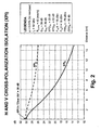
- the XPI is defined as the ratio, at the receiver, between the power received on one polarization and that received over the same polarization due to the transmission over the orthogonal channel.
- XPI H P w RX H ⁇ H P w RX V ⁇ H
- XPI V P w RX V ⁇ V P w RX H ⁇ V
- w RX (H ⁇ H) is the power transmitted on the H polarization and received on H, and so on for the other terms.
- the 'Required Margin for Rain' must be intended as the 'Required Margin' calculated for a given probability (for example the 0.01% of the overall time). If a more rainy region or/and a lower probability is considered, the 'Required Margin' will increase.
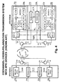
- the two stations A and B include a first transmission-and-reception section connected to the H-circulator and a second transmission-and-reception section connected to the V-circulator.
- Each H/V section includes a transmitter and a receiver.
- the H-section comprises a receiver REC-H-A, equipped with a XPIC device, and a transmitter TRANS-H-A;
- the V-section comprises a receiver REC-V-A, equipped with a XPIC device, and a transmitter TRANS-V-A.
- the H-section comprises a receiver REC-H-B, equipped with a XPIC device, and a transmitter TRANS-H-B
- the V-section comprises a receiver REC-V-B, equipped with a XPIC device, and a transmitter TRANS-V-B.
- the couple of transmitters are synchronised by a signal OLTX, and the couple of receivers by a signal OLRX, both acting on the respective local oscillators.
- D1a and D2a are indicated the baseband transmission signals of STATION-A, respectively horizontally or vertically polarized.
- D1b and D2b indicate the baseband transmission signals of STATION-B, respectively horizontally or vertically polarized.
- the signals D1a, D2a and D1b, D2b are the ones further indicated as reception signals of the destination stations B and A, respectively.
- the block diagram of STATION-B shows the detail of the two receivers REC-H-B and REC-V-B, including a front-end section FRT-H and FRT-V followed by a respective demodulator DEMOD-H and DEMOD-V.
- Each front-end FRT-H and FRT-V includes a Local Oscillator (LO) for the RF/IF conversion.
- LO Local Oscillator
- the two local oscillators are controlled by the synchronisation signal OLRX outputted by a carrier recovery circuit of the PLL (Phase-Locked Loop) type (not shown) driven by the RX input data.
- the description of the two receivers is similar, so that the only REC-H-B is considered.
- the demodulator DEMOD-H includes two IF/BB frequency conversion stages, a first one is connected to the front-end FRT-H and a second one is connected to the front-end FRT-V.
- the two IF/BB stages receive the two intermediate frequency signals, either the IF on the direct H path or the IF X coming from the orthogonal V path, and convert them to baseband BB for the successive processing.
- VCO Voltage Controlled Oscillator
- the VCO is controlled by a symbol synchronisation recovery circuit, not shown in fig.4 so as the A/D and D/A converters.
- the IF output of the direct IF/BB stage is connected to a first input of a digital adder.
- the IF x output of the transversal IF/BB stage is connected to the input of an XPIC device, which provides a correction signal (-) at the second input of the digital adder.
- the output signal of the digital adder reaches the input of a block ATDE (Adaptive Time Delay Equaliser) which outputs a time equalised and cross-polar interference-corrected signal D1a.
- ATDE Adaptive Time Delay Equaliser
- the operation of the XPIC device is controlled in a known manner by a block CTRL that receives both the orthogonally polarized signal D1a and D2a present at the output of STATION-B.
- the XPIC device is, for example, a T/2 spaced adaptive FIR filter that estimates the cross-polar interference for the aim of subtracting it from the useful signal.
- XPIC cross-polar Improvement Factor
- the XPIC device is the ideal countermeasure against the interference from orthogonal polarization. It is the only one possible when the modulation format employed in the CC system is more complex, for example, than 32TCM; because in this case the system is too sensible to the interference from the orthogonal polarization.
- an interfering signal characterized by a given value of C/I [dB]
- C/I [dB] is given by:
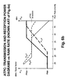
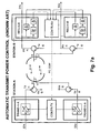
- the cochannel system of fig.4 is usually completed with the embodiment of an Automatic Transmission Power Control (ATPC), as the one depicted in fig.6a .
- ATC Automatic Transmission Power Control
- fig.6a the two independent loops to control the pair of relevant transmitters are shown for the only STATION-A.
- Each of the two transmitters TRANS-H-A and TRANS-V-A includes a variable RF power amplifier and a gain control circuit.
- the two gain control circuits are respectively indicated as CONTR-H-A and CONTR-V-A, respectively.
- PC_COM_H_A and PC_COM_V_A act upon the reception of respective power control signals PC_COM_H_A and PC_COM_V_A coming from dual control circuits CONTR-H-B and CONTR-V-B belonging to the corresponding receivers REC-H-B and REC-V-B inside STATION-B.
- the transmission of PC_COM_H_A and PC_COM_V_A signals can advantageously avail of two feedback radio channels.
- An envelope detector diode inside the two receivers REC-H-A and REC-V-A inside STATION-B is used to sense the attenuation of the reception signal RX on the respective H and V paths. The information about the attenuation is transferred to the control circuits CONTR-H-B and CONTR-V-B.
- These circuits calculate the incremental power steps, either positive or negative, and generate two power control commands PC_COM_H_A and PC_COM_V_A for the two transmitters TRANS-H-A and TRANS-V-A inside STATION-A.
- the two power control commands PC_COM_H_A and PC_COM_V_A are translated by the two circuits CONTR-H-A and CONTR-V-A into gain control voltages for the AGCs (Automatic Gain Control) of the two RF transmission power amplifiers.
- the ATPC functionality of fig.6a automatically controls in a closed-loop scheme the transmission power on the relevant H/V channel in order to counteract all the causes of attenuation typical of a line-of-sight radio link, for example, rain and multipath.
- a fast closed-loop power control is needed to compensate selective multipath fading, while the rain fading is a slower phenomenon prevalent over 10 GHz.
- the present invention is only involved with rain fading.
- the ATPC functionality allows for the same availability obtained by transmitting the maximum power but, at the same time, limiting the transmission power during Clear air conditions thus reducing the produced interference to other links and saving power.
- the cochannel system of fig.6a and more in general all the radio systems equipped with the ATPC, in clear air condition usually transmit at the minimum power P MIN , because the power received is strong enough.
- P TH ATPC a given threshold
- the ATPC loop instructs via the power control commands the relevant transmitter to increase the transmitted power in order to keep the received power as constant as possible and close to the given threshold (P TH ATPC ).
- the two transmission powers can be increased as far as they separately reach the maximum power P MAX .
- P MAX - P MIN the power received on the H polarisation
- the V polarisation decreases more rapidly as the rain increases.
- increasing the rain the result of the two independent ATPCs is that the power of the H transmitter is increased faster than the power of the V transmitter. This behaviour is highlighted by different slopes of the H/V curves. So we have to take into account that the ATPC introduces automatically a positive difference ⁇ P ATPC between the transmission powers P TX H and P TX V in order to optimally handles Clear air and initial rain conditions.
- the STATION-A includes an unique power control block CONTR-TX connected to the two variable RF power amplifiers of the two transmitters TRANS-H-A and TRANS-V-A.
- the CONTR-TX block receives a power control command PC_COM from a CONTR-RX power control block included in STATION-B.
- Each of the two receivers REC-H-B and REC-V-B includes: "a first level detector (the upper diode) for detecting the reception intensity of a microwave of the object frequency channel, and a second level detector (the lower diode preceded by a notch filter which stops the signal of the object frequency channel) for detecting the reception intensity of another frequency channel adjacent to the object frequency channel. All the level detectors forward their power measures to the common CONTR-RX block".
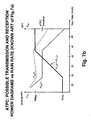
- the successive fig.7b attempts to illustrate the behaviour of the power control system of fig.7a , in particular of the CONTR-RX block.
- the power control system of fig.7a is fast enough for counteracting the Rayleigh fading, it also can be responsive for counteracting the rain fading if the case it needed.
- the two transmission powers P TX H and P TX V are equally increased of a ⁇ P linearly increasing with the rain rate.
- a corresponding ⁇ P consequently appears between the reception powers P RX V and P RX H during all the power control range and remains in the saturation region.
- the ⁇ P gap on the reception power is enough to consider non optimal the handling of rain attenuation, either inside or outside the control range.
- the equal increase of H and V transmission powers for preventing cross-polar interferences due to Rayleigh fading generates as a consequence an overpower of the V channel other than the one strictly needed to counteract the rain fading.
- overpower is costly, the major drawback is a considerable decreasing of the Cross Polar Isolation (XPI) and a worsening of the performance of the link with the rain attenuation.
- the H polarization will be always disadvantaged also in the presence of the XPIC device but, as the interference from orthogonal polarization is concerned, if the modulation format is not too complex (for example 32TCM or less) and the radio frequency band fall into the range for which the overall performance due to the radio propagation is governed from rain (above 10 GHz), it is possible to look for an alternative more convenient than XPIC device and without the drawbacks of the method disclosed in the NEC's patent. Furthermore, for more complex modulation formats less cumbersome XPIC devices are preferable or in alternative best performances with the same XPIC.
- the main object of the present invention is that to overcome the aforementioned drawbacks of the known art due to the rain attenuation and indicate an optimal transmission power setting method and system for a line-of-sight radio link employing cross-polarized cochannel signals.
- Further object of the invention is that to dynamically control the optimal power setting in a closed-loop ATPC.
- This operation permits mainly to improve the XPI H of the factor ⁇ P [dB] (see Eq.7), which is the parameter that measures the interference from orthogonal polarization (see fig.2 ).
- the XPI v will be consequently reduced of the same factor ⁇ P [dB], but for this parameter there is enough margin to do it.
- the optimum ⁇ P can be kept constant for all the transmission time (whether in 'clear air' or during rain conditions) or varied dynamically according to an embodiment of the invention addressed to radio systems with ATPC.
- the ATPC can be embodied for featuring the power setting either on the transmission or the reception side, indifferently.
- the ATPC of the present invention holds the optimum ⁇ P inside the power control saturation range of the horizontally polarized signal. (see fig.14 and fig.16 ).
- the ATPC of the present invention strongly differs from the ones disclosed in the NEC' s patent in which a ⁇ P between the H and V transmission powers is not implemented, so that an unfit ⁇ P appears between the reception signals.
- fig.10 a 'static' (without ATPC) power setting system in accordance with a preferred embodiment of the invention is depicted.
- the power setting system of fig.10 gives the best possible performance in terms of unavailability to a cochannel system without XPIC, although the use of the XPIC for high level modulations is possible and further improves the overall performances.
- STATION-A ( fig.4 ) including the two TRANS-H-A and TRANS-V-A transmitters and a functional block named CONTROL LOGIC is shown.
- the two transmitters include a variable-gain RF power amplifier and an envelope detector diode D-H and D-V, according to the H, V notation, for detecting the level of the relevant transmission signal.
- the control logic block receives an optimum ⁇ P value (expressed in dB) together with the voltages representing the two envelopes detected on the H and V channels, and calculates two control signals for regulating the gain of the two RF power amplifiers in order Lo keep constant, and equal to the optimum ⁇ P, the difference between the transmission powers (expressed in dB) on the H and V channels.
- the optimum 'static' ⁇ P is calculated in advance (off-line) during the planning of the link, and successively kept constant for all the transmission time.
- the limitation to the optimum ⁇ P value stated in Eq.16 takes into account rain and 'clear air' conditions.
- the value assigned to ⁇ P cannot be too large, otherwise the interference of the H channel on the V should become too strong.
- the power on the V channel must be ⁇ P dB always lower than that on the H channel, with that the XPI V on the V channel (defined as the C/I when the interfering signal is that on the H channel) is reduced consequently.
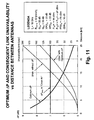
- ⁇ P the following maximum value for ⁇ P can be defined as a function of the two antenna characteristics and of the receiver threshold:
- ⁇ P OPT is higher than ⁇ P MAX , otherwise it is lower. This is not the rule; it depends from the data assumed for the radio link. For example if we consider a more rainy zone (with Rain Rate higher than 42 mm/h) the values of ⁇ P OPT will increase. In general, three cases are possible:
- ⁇ P OPT is set by the circuitry of fig.10 , the ratio s/(n+i) versus rain rate can be evaluated for the two polarisations.
- the curves in fig.12 calculated using the parameters indicated in the LEGENDA.
- Another preferred embodiment of the invention covers systems with ATPC; the aims of this functionality has been described in the introduction. Then, to fully exploit the advantages of the optimum ⁇ P even in ATPC systems, the parameters of the ATPC shall be set in the manner to obtain the following behaviour for a given distance:
- the most straightforward approach is to bound the maximum transmitted power of the V channel in the ATPC system to be ⁇ P OPT below the power of the H channel (thus preventing V channel to increase its power up to the maximum). Another way is to act in the receiver to control the received power of H and V channels to be the same. This second approach gives slightly different results but the performances are very similar.
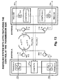
- the most straightforward approach correspond to a first variant of the invention embodied for ATPC, as shown in fig.13 , while the second approach corresponds to a second variant shown in fig.15 .
- the partial representation of STATION-A includes the two transmitters TRANS-H-A and TRANS-V-A and a sole control block named CONTR-TX.
- the two transmitters each includes a variable-gain RF power amplifier.
- the partial representation of STATION-B includes the two receivers REC-H-B and REC-V-B, each of them includes an envelope detector diode followed by a control block.
- the two diodes are labelled D-H and D-V, and the control blocks are named CONTR-RX-H and CONTR-RX-V (in accordance with the H, V notation), the latter generate two respective commands PW-COM-H and PW-COM-V which include the corrections sent to the CONTR-TX block inside STATION-A (via two feedback radio cannels) for controlling the power level of the H and V transmission signals.
- the two commands PW-COM-H and PW-COM-V are generated independently with each other, as in conventional ATPC, by comparing the detected envelopes with the ATPC threshold.
- the control block CONTR-TX receives the two commands PW-COM-H and PW-COM-V and the optimum value ⁇ P OPT (calculated in advance), filters the received corrections, and generates two control signals for regulating the AGCs of the two RF power amplifiers, in order to operate as the P TX H and P TX V curves versus rain rate indicated in fig.14 .
- the partial representation of STATION-A includes the two TRANS-H-A and TRANS-V-A transmitters.
- the two transmitters include a variable-gain RF power amplifier and a and a control block.
- the two control blocks are named CONTR-TX-H and CONTR-TX-V, accordingly.
- the partial representation of STATION-B includes the two receivers REC-H-B and REC-V-B and a sole control block named CONTR-RX.
- the two receivers each includes an envelope detector diode for sensing the power level of the reception signal.
- the two diodes are labelled D-H and D-V (in accordance with the H, V notation).
- the detected envelopes are sent to the control block CONTR-RX, that calculates in correspondence two power control commands PC_COM_H and PC_COM_V directed (via two feedback radio channels) to the control blocks CONTR-TX-H and CONTR-TX-V, respectively.
- the control block CONTR-RX calculates instant by instant the difference ⁇ P between each detected envelope.
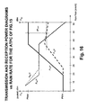
- the differences are filtered and translated into power control commands PC_COM_H and PC_COM_V suitable for equating the reception powers on the H and V channels, as indicated by the P RX H and P RX V curves versus rain rate of fig.16 .
- the two blocks CONTR-TX-H and CONTR-TX-V act on the AGCs of the two RF power amplifiers in accordance with the received power control commands, in order to obtain the P TX H and P TX V curves versus rain rate indicated in fig.16 . It is of course possible, though probably useless, to distribute the filtering function between transmitter and receiver.
- the two received powers P RX H and P RX V are very close to each other for all the values of the rain rate (the maximum difference can be evaluated as less than 0.5 dB). This also implicates equal interference conditions on the two H and V channels.
- the two transmission powers P TX H and P TX V versus rain rate for the ideal ATPC which have been calculated starting from the detected reception powers, are shown. Please note that the ideal condition would require that P MIN of V channel be lower than 8 dBm, thus requesting an ATPC range, larger than the actual one.
- the s/(n+i) ratio versus rain rate corresponding to ideal ATPC is shown; the ratio is the same for the two polarizations, of course.
- a possible schema very close to 'ideal ATPC' is the one of the second variant shown in fig.15 .
- the deviation from ideality visible in fig.15 is not relevant, because it occurs in low rain fading area where the s/(n+i) ratio is far from threshold, so that the non ideal behaviour has no consequences on the performance.
- the behaviour of the circuital embodiment of fig.15 is very close to the ideal at rain rates above 30 mm/h.
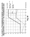
- Another possible implementation is the one of the first variant shown in fig.13 .
- the control block CONTR-TX operates on the H channel as usual and saturates the V channel at a maximum power ⁇ P OPT [dB] below the maximum power P MAX of the H channel. Therefore a non ideal behaviour is introduced as shown in fig.20 at rain rates above 35 mm/h. There is always the non ideal behaviour due to P MIN , as in the second variant, which is not particularly important in this context.
- the specified behaviour of the real transmission power P TX V is therefore defined as follows with respect to ideal behaviour:
Landscapes
- Engineering & Computer Science (AREA)
- Computer Networks & Wireless Communication (AREA)
- Signal Processing (AREA)
- Radio Transmission System (AREA)
- Transmitters (AREA)
- Near-Field Transmission Systems (AREA)
- Mobile Radio Communication Systems (AREA)
- Radio Relay Systems (AREA)
Claims (15)
- Sendeleistungs-Einstellverfahren für eine Kreuzpolarisations-Cokanal-Line-of-Sight-Funkstrecke, die Regendämpfung ausgesetzt ist, dadurch gekennzeichnet, dass ein optimaler positiver Differenzwert (ΔPOPT) zwischen den Logarithmen der Sendeleistungen der horizontal (H) und vertikal (V) polarisierten Signale eingestellt wird; wobei die optimale Differenz (ΔPOPT) berechnet wird, um über gleiche Wahrscheinlichkeit von Unverfügbarkeit der Strecke für beide kreuzpolarisierte Signale (H, V) bei gegebener Länge der Strecke, der Regenzone und der entsprechenden Schwelle für das Verhältnis von Signal zu Rauschen plus Störungen zu verfügen.
- Verfahren des vorherigen Anspruchs, dadurch gekennzeichnet, dass die optimale positive Differenz (ΔPOPT) auf kleiner oder gleich einem maximalen Differenzwert (ΔPMAX) begrenzt wird, der für eine Klarluftbedingung berechnet wird.
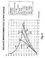
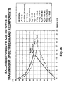
- Verfahren nach Anspruch 1 oder 2, dadurch gekennzeichnet, dass die gegebene Länge der Strecke eine maximale Länge (DMAX) ist, die berechnet wird durch Erzwingen von Gleichheit der Gleichgewichte zwischen der Fading-Reserve (FM) und der erforderlichen Reserve für Regen (RM) gegenüber der Länge der Strecke der horizontal und vertikal polarisierten Signale (H, V).
- Verfahren nach einem der vorhergehenden Ansprüche, dadurch gekennzeichnet, dass der optimale positive Differenzwert (ΔPOPT) im Voraus berechnet wird und für die gesamte Übertragungszeit gehalten wird.
- Verfahren nach Anspruch 1, dadurch gekennzeichnet, dass der optimale positive Differenzwert (ΔPOPT) in Verbindung mit einer Leistungsregelschleife eingestellt wird, die an beiden kreuzpolarisierten Übertragungssignalen (H, V) wirkt.
- Verfahren des vorherigen Anspruchs, dadurch gekennzeichnet, dass eine mit der maximal sendbaren Leistung (PMax) und Breite des Leistungsregelbereichs kompatible minimale Sendeleistung (PMin) für beide kreuzpolarisierte Signale (H, V) eingestellt wird.
- Verfahren nach Anspruch 5 oder 6, dadurch gekennzeichnet, dass der Leistungspegel des vertikal polarisierten Übertragungssignals (PTXV) konstant gehalten wird, wenn seine Summierung mit der im Voraus berechneten optimalen positiven Differenz (ΔPOPT) die maximale Leistung (PMAX) erreicht, die dem horizontal polarisierten Übertragungssignal erlaubt wird (PTXH).
- Verfahren nach Anspruch 5 oder 6, dadurch gekennzeichnet, dass der optimale positive Differenzwert (ΔPOPT) durch Gleichsetzen des Verhältnisses von Signal zu Rauschen plus Störungen der beiden kreuzpolarisierten Empfangssignale (H, V) erhalten wird.
- Sendeleistungs-Einstellsystem für eine Kreuzpolarisations-Cokanal-Line-of-Sight-Funkstrecke, die Regendämpfung ausgesetzt ist, dadurch gekennzeichnet, dass es Folgendes umfasst: Steuermittel (CONTROL LOGIC, CONTR-TX, CONTR-RX-H, CONTR-RX-V, CONTR-RX, CONTR-TX-H, CONTR-TX-V) zum Einstellen eines optimalen positiven Differenzwerts (ΔPOPT) zwischen den Logarithmen der Sendeleistung der horizontal (H) und vertikal (V) polarisierten Signale, um über gleiche Wahrscheinlichkeit von Unverfügbarkeit der Strecke für beide kreuzpolarisierte Signale (H, V) bei gegebener Länge der Strecke, der Regenzone und der entsprechenden Schwelle für das Verhältnis von Signal zu Rauschen plus Störungen zu verfügen.
- System des vorherigen Anspruchs, dadurch gekennzeichnet, dass die Steuermittel (CONTROL LOGIC) in der Sendestation (STATION-A) angeordnet werden, um die Maße der Sendeleistungspegel (PTXH, PTXV) der horizontal (H) und vertikal (V) polarisierten Signale an dem Ausgang der relevanten Detektionsmittel (D-H, D-V) zu empfangen, und ferner den Wert der optimalen positiven Differenz (ΔPOPT), die im Voraus berechnet wird, zu empfangen und entsprechend zwei Verstärkungsregelbefehle zu erzeugen, die zu den Sendern der kreuzpolarisierten Signale (TRANS-H-A, TRANS-V-A) geleitet werden, um die optimale Differenz (ΔPOPT) zu erzielen und sie für die gesamte Übertragungszeit konstant zu halten.
- System nach Anspruch 9, dadurch gekennzeichnet, dass die Steuermittel (CONTR-TX, CONTR-RX-H, CONTR-RX-V) in zwei Teile aufgeteilt sind, einen ersten (CONTR-RX-H, CONTR-RX-V), der in der Empfangsstation (STATION-B) angeordnet ist, und einen zweiten (CONTR-TX) in der Sendestation (STATION-A), um eine Leistungsregelschleife auszuführen, die einen gegebenen dynamischen Leistungsumfang aufweist:- wobei die ersten Steuermittel (CONTR-RX-H, CONTR-RX-V) dafür ausgelegt sind, die Maße der Empfangsleistungspegel (PRXH, PRXV) der horizontal (H) und vertikal (V) polarisierten Signale an dem Ausgang relevanter Detektionsmittel (D-H, D-V) zu empfangen und die Differenzen zwischen jedem Maß und einer Zwischenleistungsschwelle zu verfolgen, um relevante Korrekturen (PW-COM-H, PW-COM-V) an den Sendeleistungen zu erzeugen;- wobei die zweiten Steuermittel (CONTR-TX) dafür ausgelegt sind, den Leistungspegel der kreuzpolarisierten Übertragungssignale (PTXH, PTXV) auf den Empfang der Korrekturen (PW-COM-H, PW-COM-V) und den optimalen Wert der positiven Differenz (ΔPOPT), der im Voraus berechnet wird, hin dynamisch zu steuern.
- System nach Anspruch 11, dadurch gekennzeichnet, dass die zweiten Steuermittel (CONTR-TX) ferner dafür ausgelegt sind, den Leistungspegel des vertikal polarisierten Übertragungssignals (PTXV) aufrechtzuerhalten, wenn seine Summierung mit dem optimalen Wert der positiven Differenz (ΔPOPT) die maximale Leistung (PMAX) erreicht, die dem horizontal polarisierten Übertragungssignal erlaubt wird (PTXH) .
- System nach Anspruch 11 oder 12, dadurch gekennzeichnet, dass die zweiten Steuermittel (CONTR-TX) Filtermittel zur zeitlichen Mittelung der Korrekturen (PW-COM-H, PW-COM-V) umfassen.
- System nach Anspruch 9, dadurch gekennzeichnet, dass die Steuermittel (CONTR-RX, CONTR-TX-H, CONTR-TX-V) in zwei Teile aufgeteilt sind, einen ersten (CONTR-RX), der in der Empfangsstation (STATION-B) angeordnet ist, und einen zweiten (CONTR-TX-H, CONTR-TX-V) in der Sendestation (STATION-A), um eine Leistungsregelschleife auszuführen, die einen gegebenen dynamischen Leistungsumfang aufweist:- wobei die ersten Steuermittel (CONTR-RX) dafür ausgelegt sind, die Maße der Empfangsleistungspegel (PRXH, PRXV) der horizontal (H) und vertikal (V) polarisierten Signale am Ausgang der relevanten Detektionsmittel (D-H, D-V) zu empfangen und jeweilige Leistungsregelbefehle (PC-COM-H, PC-COM-V) zu erzeugen, die relevante Korrekturen an den entsprechenden Sendeleistungen (PTXH, PTXV) zum dynamischen Gleichsetzen der Empfangsleistungspegel (PRXH, PRXV) umfassen;- wobei die zweiten Steuermittel (CONTR-TX-H, CONTR-TX-V) dafür ausgelegt sind, an der Verstärkung der beiden Sender (TRANS-H-A, TRANS-V-A) der kreuzpolarisierten Signale (H, V) gemäß den Leistungsregelbefehlen (PC-COM-H, PC-COM-V) zu wirken.
- System nach Anspruch 13, dadurch gekennzeichnet, dass die ersten Steuermittel (CONTR-RX) Filtermittel zum zeitlichen Mitteln der Leistungsregelbefehle (PC-COM-H, PC-COM-V) umfassen.
Priority Applications (4)
| Application Number | Priority Date | Filing Date | Title |
|---|---|---|---|
| EP03425608A EP1517455B1 (de) | 2003-09-18 | 2003-09-18 | Sendeleistungsregelungsverfahren für orthogonal polarisierte Signale |
| ES03425608T ES2344783T3 (es) | 2003-09-18 | 2003-09-18 | Procedimiento de control de la potencia de transmision para señales de polarizacion ortogonal. |
| DE60333097T DE60333097D1 (de) | 2003-09-18 | 2003-09-18 | Sendeleistungsregelungsverfahren für orthogonal polarisierte Signale |
| AT03425608T ATE472200T1 (de) | 2003-09-18 | 2003-09-18 | Sendeleistungsregelungsverfahren für orthogonal polarisierte signale |
Applications Claiming Priority (1)
| Application Number | Priority Date | Filing Date | Title |
|---|---|---|---|
| EP03425608A EP1517455B1 (de) | 2003-09-18 | 2003-09-18 | Sendeleistungsregelungsverfahren für orthogonal polarisierte Signale |
Publications (2)
| Publication Number | Publication Date |
|---|---|
| EP1517455A1 EP1517455A1 (de) | 2005-03-23 |
| EP1517455B1 true EP1517455B1 (de) | 2010-06-23 |
Family
ID=34178699
Family Applications (1)
| Application Number | Title | Priority Date | Filing Date |
|---|---|---|---|
| EP03425608A Expired - Lifetime EP1517455B1 (de) | 2003-09-18 | 2003-09-18 | Sendeleistungsregelungsverfahren für orthogonal polarisierte Signale |
Country Status (4)
| Country | Link |
|---|---|
| EP (1) | EP1517455B1 (de) |
| AT (1) | ATE472200T1 (de) |
| DE (1) | DE60333097D1 (de) |
| ES (1) | ES2344783T3 (de) |
Families Citing this family (4)
| Publication number | Priority date | Publication date | Assignee | Title |
|---|---|---|---|---|
| EP2795975B1 (de) * | 2011-12-22 | 2015-12-16 | Telefonaktiebolaget LM Ericsson (PUBL) | Automatische sendeleistungssteuerung in xpic-konfiguration für drahtlose anwendungen |
| EP3024290B1 (de) | 2013-08-20 | 2018-05-23 | Huawei Technologies Co., Ltd. | Verfahren zur sendeleistungsregelung in einem mehrkanalsystem, empfangsende und übertragungsende |
| WO2020124502A1 (zh) * | 2018-12-20 | 2020-06-25 | Oppo广东移动通信有限公司 | 一种功率分配方法、终端设备及存储介质 |
| US12512877B1 (en) | 2025-07-02 | 2025-12-30 | Imam Mohammad Ibn Saud Islamic University | System and method for mitigating rain-induced crosstalk in wireless communications |
Family Cites Families (1)
| Publication number | Priority date | Publication date | Assignee | Title |
|---|---|---|---|---|
| JP2882147B2 (ja) * | 1991-11-27 | 1999-04-12 | 日本電気株式会社 | 送信電力制御方式 |
-
2003
- 2003-09-18 AT AT03425608T patent/ATE472200T1/de not_active IP Right Cessation
- 2003-09-18 EP EP03425608A patent/EP1517455B1/de not_active Expired - Lifetime
- 2003-09-18 ES ES03425608T patent/ES2344783T3/es not_active Expired - Lifetime
- 2003-09-18 DE DE60333097T patent/DE60333097D1/de not_active Expired - Lifetime
Also Published As
| Publication number | Publication date |
|---|---|
| DE60333097D1 (de) | 2010-08-05 |
| ATE472200T1 (de) | 2010-07-15 |
| ES2344783T3 (es) | 2010-09-07 |
| EP1517455A1 (de) | 2005-03-23 |
Similar Documents
| Publication | Publication Date | Title |
|---|---|---|
| CA1215745A (en) | Transmitter power control circuit | |
| US5566165A (en) | Transmission power control method and a communication system using the same | |
| EP0548939B1 (de) | System zur Steuerung der Sendeleistung mit Gewährleistung einer konstanten Signalqualität in einem Mobilkommunikationsnetzwerk | |
| US5794129A (en) | Mobile communication system and base station for use therein | |
| US5839056A (en) | Method and apparatus for controlling transmission power of a radio transmitter | |
| US7920889B2 (en) | Transmitting apparatus, receiving apparatus and transmission power control method | |
| US20020068540A1 (en) | Communication receiver having reduced dynamic range by reducing the fixed range of the amplifier and increasing the variable gain via a gain control circuit | |
| US8050702B2 (en) | Mobile station and transmission power control method in mobile station | |
| US20110081935A1 (en) | Lte-a system and uplink power control method thereof | |
| RU2422995C2 (ru) | Снижение тока потребления в цепях с rx разнесением | |
| JP2008530957A (ja) | 移動局の通信状態におけるアンテナ調整システムおよび方法 | |
| WO1999021291A1 (en) | Power output control system for rf communications system | |
| MXPA04002906A (es) | Metodo y aparato para control de potencia de circuito externo de enlace de regreso multicanal. | |
| US8755292B2 (en) | Apparatus and method for controlling uplink transmission power in a communication system | |
| EP1517455B1 (de) | Sendeleistungsregelungsverfahren für orthogonal polarisierte Signale | |
| US20020001336A1 (en) | Spread spectrum communication system and method therefor | |
| US9432948B2 (en) | Automatic transmit power control in XPIC configuration for wireless applications | |
| US7379747B2 (en) | Method for controlling output power of handheld terminal in mobile communication system | |
| US4769825A (en) | Communications transmission system for electromagnetic waves | |
| Saghaei et al. | Variable step closed-loop power control in cellular wireless CDMA systems under multipath fading | |
| US20100240409A1 (en) | Wireless communication system, wireless base station, wireless terminal station, and transmission power control method using the same | |
| EP1116343B1 (de) | Gerät und verfahren zur leistungsregelung eines kommunikationsgerätes | |
| US7158490B1 (en) | Apparatus, and associated method, for effectuating power control of a communication device | |
| Sampietro et al. | Cochannel systems: optimum link length with polarisation driven power control for systems working at high frequencies and without copolar canceller | |
| Villier et al. | On the application of uplink optimum combining to base station reception |
Legal Events
| Date | Code | Title | Description |
|---|---|---|---|
| PUAI | Public reference made under article 153(3) epc to a published international application that has entered the european phase |
Free format text: ORIGINAL CODE: 0009012 |
|
| AK | Designated contracting states |
Kind code of ref document: A1 Designated state(s): AT BE BG CH CY CZ DE DK EE ES FI FR GB GR HU IE IT LI LU MC NL PT RO SE SI SK TR |
|
| AX | Request for extension of the european patent |
Extension state: AL LT LV MK |
|
| 17P | Request for examination filed |
Effective date: 20050922 |
|
| AKX | Designation fees paid |
Designated state(s): AT BE BG CH CY CZ DE DK EE ES FI FR GB GR HU IE IT LI LU MC NL PT RO SE SI SK TR |
|
| RAP1 | Party data changed (applicant data changed or rights of an application transferred) |
Owner name: SIEMENS S.P.A. |
|
| RAP1 | Party data changed (applicant data changed or rights of an application transferred) |
Owner name: NOKIA SIEMENS NETWORKS S.P.A. |
|
| GRAP | Despatch of communication of intention to grant a patent |
Free format text: ORIGINAL CODE: EPIDOSNIGR1 |
|
| GRAS | Grant fee paid |
Free format text: ORIGINAL CODE: EPIDOSNIGR3 |
|
| GRAA | (expected) grant |
Free format text: ORIGINAL CODE: 0009210 |
|
| AK | Designated contracting states |
Kind code of ref document: B1 Designated state(s): AT BE BG CH CY CZ DE DK EE ES FI FR GB GR HU IE IT LI LU MC NL PT RO SE SI SK TR |
|
| REG | Reference to a national code |
Ref country code: CH Ref legal event code: EP |
|
| REG | Reference to a national code |
Ref country code: IE Ref legal event code: FG4D |
|
| REF | Corresponds to: |
Ref document number: 60333097 Country of ref document: DE Date of ref document: 20100805 Kind code of ref document: P |
|
| REG | Reference to a national code |
Ref country code: ES Ref legal event code: FG2A Ref document number: 2344783 Country of ref document: ES Kind code of ref document: T3 |
|
| REG | Reference to a national code |
Ref country code: NL Ref legal event code: VDEP Effective date: 20100623 |
|
| PG25 | Lapsed in a contracting state [announced via postgrant information from national office to epo] |
Ref country code: SE Free format text: LAPSE BECAUSE OF FAILURE TO SUBMIT A TRANSLATION OF THE DESCRIPTION OR TO PAY THE FEE WITHIN THE PRESCRIBED TIME-LIMIT Effective date: 20100623 |
|
| PG25 | Lapsed in a contracting state [announced via postgrant information from national office to epo] |
Ref country code: SI Free format text: LAPSE BECAUSE OF FAILURE TO SUBMIT A TRANSLATION OF THE DESCRIPTION OR TO PAY THE FEE WITHIN THE PRESCRIBED TIME-LIMIT Effective date: 20100623 Ref country code: FI Free format text: LAPSE BECAUSE OF FAILURE TO SUBMIT A TRANSLATION OF THE DESCRIPTION OR TO PAY THE FEE WITHIN THE PRESCRIBED TIME-LIMIT Effective date: 20100623 Ref country code: AT Free format text: LAPSE BECAUSE OF FAILURE TO SUBMIT A TRANSLATION OF THE DESCRIPTION OR TO PAY THE FEE WITHIN THE PRESCRIBED TIME-LIMIT Effective date: 20100623 |
|
| PG25 | Lapsed in a contracting state [announced via postgrant information from national office to epo] |
Ref country code: GR Free format text: LAPSE BECAUSE OF FAILURE TO SUBMIT A TRANSLATION OF THE DESCRIPTION OR TO PAY THE FEE WITHIN THE PRESCRIBED TIME-LIMIT Effective date: 20100924 |
|
| PG25 | Lapsed in a contracting state [announced via postgrant information from national office to epo] |
Ref country code: EE Free format text: LAPSE BECAUSE OF FAILURE TO SUBMIT A TRANSLATION OF THE DESCRIPTION OR TO PAY THE FEE WITHIN THE PRESCRIBED TIME-LIMIT Effective date: 20100623 Ref country code: NL Free format text: LAPSE BECAUSE OF FAILURE TO SUBMIT A TRANSLATION OF THE DESCRIPTION OR TO PAY THE FEE WITHIN THE PRESCRIBED TIME-LIMIT Effective date: 20100623 |
|
| PG25 | Lapsed in a contracting state [announced via postgrant information from national office to epo] |
Ref country code: CY Free format text: LAPSE BECAUSE OF FAILURE TO SUBMIT A TRANSLATION OF THE DESCRIPTION OR TO PAY THE FEE WITHIN THE PRESCRIBED TIME-LIMIT Effective date: 20100623 Ref country code: BE Free format text: LAPSE BECAUSE OF FAILURE TO SUBMIT A TRANSLATION OF THE DESCRIPTION OR TO PAY THE FEE WITHIN THE PRESCRIBED TIME-LIMIT Effective date: 20100623 Ref country code: SK Free format text: LAPSE BECAUSE OF FAILURE TO SUBMIT A TRANSLATION OF THE DESCRIPTION OR TO PAY THE FEE WITHIN THE PRESCRIBED TIME-LIMIT Effective date: 20100623 Ref country code: RO Free format text: LAPSE BECAUSE OF FAILURE TO SUBMIT A TRANSLATION OF THE DESCRIPTION OR TO PAY THE FEE WITHIN THE PRESCRIBED TIME-LIMIT Effective date: 20100623 Ref country code: PT Free format text: LAPSE BECAUSE OF FAILURE TO SUBMIT A TRANSLATION OF THE DESCRIPTION OR TO PAY THE FEE WITHIN THE PRESCRIBED TIME-LIMIT Effective date: 20101025 Ref country code: CZ Free format text: LAPSE BECAUSE OF FAILURE TO SUBMIT A TRANSLATION OF THE DESCRIPTION OR TO PAY THE FEE WITHIN THE PRESCRIBED TIME-LIMIT Effective date: 20100623 |
|
| PG25 | Lapsed in a contracting state [announced via postgrant information from national office to epo] |
Ref country code: MC Free format text: LAPSE BECAUSE OF NON-PAYMENT OF DUE FEES Effective date: 20100930 Ref country code: DK Free format text: LAPSE BECAUSE OF FAILURE TO SUBMIT A TRANSLATION OF THE DESCRIPTION OR TO PAY THE FEE WITHIN THE PRESCRIBED TIME-LIMIT Effective date: 20100623 |
|
| PLBE | No opposition filed within time limit |
Free format text: ORIGINAL CODE: 0009261 |
|
| REG | Reference to a national code |
Ref country code: CH Ref legal event code: PL |
|
| STAA | Information on the status of an ep patent application or granted ep patent |
Free format text: STATUS: NO OPPOSITION FILED WITHIN TIME LIMIT |
|
| 26N | No opposition filed |
Effective date: 20110324 |
|
| REG | Reference to a national code |
Ref country code: DE Ref legal event code: R097 Ref document number: 60333097 Country of ref document: DE Effective date: 20110323 |
|
| PG25 | Lapsed in a contracting state [announced via postgrant information from national office to epo] |
Ref country code: CH Free format text: LAPSE BECAUSE OF NON-PAYMENT OF DUE FEES Effective date: 20100930 Ref country code: IE Free format text: LAPSE BECAUSE OF NON-PAYMENT OF DUE FEES Effective date: 20100918 Ref country code: LI Free format text: LAPSE BECAUSE OF NON-PAYMENT OF DUE FEES Effective date: 20100930 |
|
| REG | Reference to a national code |
Ref country code: GB Ref legal event code: 732E Free format text: REGISTERED BETWEEN 20120719 AND 20120725 |
|
| REG | Reference to a national code |
Ref country code: DE Ref legal event code: R081 Ref document number: 60333097 Country of ref document: DE Owner name: DRAGONWAVE S.A R.L., LU Free format text: FORMER OWNER: NOKIA SIEMENS NETWORKS S.P.A., CASSINA DE' PECCHI, MILANO, IT Effective date: 20120731 Ref country code: DE Ref legal event code: R081 Ref document number: 60333097 Country of ref document: DE Owner name: NOKIA SIEMENS NETWORKS ITALIA S.P.A., IT Free format text: FORMER OWNER: NOKIA SIEMENS NETWORKS S.P.A., CASSINA DE' PECCHI, IT Effective date: 20120731 Ref country code: DE Ref legal event code: R081 Ref document number: 60333097 Country of ref document: DE Owner name: NOKIA SIEMENS NETWORKS ITALIA S.P.A., IT Free format text: FORMER OWNER: NOKIA SIEMENS NETWORKS S.P.A., CASSINA DE' PECCHI, MILANO, IT Effective date: 20120731 |
|
| PG25 | Lapsed in a contracting state [announced via postgrant information from national office to epo] |
Ref country code: LU Free format text: LAPSE BECAUSE OF NON-PAYMENT OF DUE FEES Effective date: 20100918 Ref country code: BG Free format text: LAPSE BECAUSE OF FAILURE TO SUBMIT A TRANSLATION OF THE DESCRIPTION OR TO PAY THE FEE WITHIN THE PRESCRIBED TIME-LIMIT Effective date: 20100623 Ref country code: HU Free format text: LAPSE BECAUSE OF FAILURE TO SUBMIT A TRANSLATION OF THE DESCRIPTION OR TO PAY THE FEE WITHIN THE PRESCRIBED TIME-LIMIT Effective date: 20101224 |
|
| REG | Reference to a national code |
Ref country code: ES Ref legal event code: PC2A Owner name: NOKIA SIEMENS NETWORKS ITALIA S.P.A. Effective date: 20120919 |
|
| PG25 | Lapsed in a contracting state [announced via postgrant information from national office to epo] |
Ref country code: TR Free format text: LAPSE BECAUSE OF FAILURE TO SUBMIT A TRANSLATION OF THE DESCRIPTION OR TO PAY THE FEE WITHIN THE PRESCRIBED TIME-LIMIT Effective date: 20100623 |
|
| REG | Reference to a national code |
Ref country code: FR Ref legal event code: CA Effective date: 20130426 Ref country code: FR Ref legal event code: CD Owner name: NOKIA SIEMENS NETWORKS ITALIA S.P.A., IT Effective date: 20130426 |
|
| REG | Reference to a national code |
Ref country code: FR Ref legal event code: TP Owner name: NOKIA SIEMENS NETWORKS ITALIA S.P.A., IT Effective date: 20130607 |
|
| PG25 | Lapsed in a contracting state [announced via postgrant information from national office to epo] |
Ref country code: BG Free format text: LAPSE BECAUSE OF FAILURE TO SUBMIT A TRANSLATION OF THE DESCRIPTION OR TO PAY THE FEE WITHIN THE PRESCRIBED TIME-LIMIT Effective date: 20100923 |
|
| PGFP | Annual fee paid to national office [announced via postgrant information from national office to epo] |
Ref country code: FR Payment date: 20131010 Year of fee payment: 11 |
|
| PGFP | Annual fee paid to national office [announced via postgrant information from national office to epo] |
Ref country code: ES Payment date: 20131029 Year of fee payment: 11 |
|
| REG | Reference to a national code |
Ref country code: FR Ref legal event code: ST Effective date: 20150529 |
|
| PG25 | Lapsed in a contracting state [announced via postgrant information from national office to epo] |
Ref country code: FR Free format text: LAPSE BECAUSE OF NON-PAYMENT OF DUE FEES Effective date: 20140930 |
|
| PG25 | Lapsed in a contracting state [announced via postgrant information from national office to epo] |
Ref country code: ES Free format text: LAPSE BECAUSE OF NON-PAYMENT OF DUE FEES Effective date: 20140919 |
|
| REG | Reference to a national code |
Ref country code: DE Ref legal event code: R081 Ref document number: 60333097 Country of ref document: DE Owner name: DRAGONWAVE S.A R.L., LU Free format text: FORMER OWNER: NOKIA SIEMENS NETWORKS ITALIA S.P.A., CASSINA DE PECCHI, IT |
|
| PGFP | Annual fee paid to national office [announced via postgrant information from national office to epo] |
Ref country code: DE Payment date: 20170928 Year of fee payment: 15 Ref country code: GB Payment date: 20170921 Year of fee payment: 15 Ref country code: IT Payment date: 20170926 Year of fee payment: 15 |
|
| REG | Reference to a national code |
Ref country code: DE Ref legal event code: R119 Ref document number: 60333097 Country of ref document: DE |
|
| GBPC | Gb: european patent ceased through non-payment of renewal fee |
Effective date: 20180918 |
|
| PG25 | Lapsed in a contracting state [announced via postgrant information from national office to epo] |
Ref country code: IT Free format text: LAPSE BECAUSE OF NON-PAYMENT OF DUE FEES Effective date: 20180918 Ref country code: DE Free format text: LAPSE BECAUSE OF NON-PAYMENT OF DUE FEES Effective date: 20190402 |
|
| PG25 | Lapsed in a contracting state [announced via postgrant information from national office to epo] |
Ref country code: GB Free format text: LAPSE BECAUSE OF NON-PAYMENT OF DUE FEES Effective date: 20180918 |