EP1517388A1 - Verfahren zur Herstellung von Bipolarplatten für Brennstoffzellen- oder Elektrolyseur-Stapel, sowie Bipolarplatte - Google Patents
Verfahren zur Herstellung von Bipolarplatten für Brennstoffzellen- oder Elektrolyseur-Stapel, sowie Bipolarplatte Download PDFInfo
- Publication number
- EP1517388A1 EP1517388A1 EP04018244A EP04018244A EP1517388A1 EP 1517388 A1 EP1517388 A1 EP 1517388A1 EP 04018244 A EP04018244 A EP 04018244A EP 04018244 A EP04018244 A EP 04018244A EP 1517388 A1 EP1517388 A1 EP 1517388A1
- Authority
- EP
- European Patent Office
- Prior art keywords
- bipolar
- plastic
- electrode plate
- strips
- electrode
- Prior art date
- Legal status (The legal status is an assumption and is not a legal conclusion. Google has not performed a legal analysis and makes no representation as to the accuracy of the status listed.)
- Granted
Links
- 239000000446 fuel Substances 0.000 title claims abstract description 36
- 238000004519 manufacturing process Methods 0.000 title claims description 16
- 239000004033 plastic Substances 0.000 claims abstract description 52
- 238000000034 method Methods 0.000 claims abstract description 49
- 238000004080 punching Methods 0.000 claims abstract description 21
- 239000000463 material Substances 0.000 claims abstract description 18
- 238000005260 corrosion Methods 0.000 claims abstract description 9
- 230000007797 corrosion Effects 0.000 claims abstract description 9
- 229910052751 metal Inorganic materials 0.000 claims description 50
- 239000002184 metal Substances 0.000 claims description 50
- 238000002347 injection Methods 0.000 claims description 33
- 239000007924 injection Substances 0.000 claims description 33
- 239000007789 gas Substances 0.000 claims description 31
- 238000009792 diffusion process Methods 0.000 claims description 25
- 239000012528 membrane Substances 0.000 claims description 20
- 239000000376 reactant Substances 0.000 claims description 12
- UFHFLCQGNIYNRP-UHFFFAOYSA-N Hydrogen Chemical compound [H][H] UFHFLCQGNIYNRP-UHFFFAOYSA-N 0.000 claims description 5
- 238000004381 surface treatment Methods 0.000 claims description 5
- 239000004734 Polyphenylene sulfide Substances 0.000 claims description 4
- 229920000069 polyphenylene sulfide Polymers 0.000 claims description 4
- 229910001220 stainless steel Inorganic materials 0.000 claims description 4
- 239000010935 stainless steel Substances 0.000 claims description 4
- 238000009826 distribution Methods 0.000 claims description 3
- RYGMFSIKBFXOCR-UHFFFAOYSA-N Copper Chemical compound [Cu] RYGMFSIKBFXOCR-UHFFFAOYSA-N 0.000 claims description 2
- 229910052802 copper Inorganic materials 0.000 claims description 2
- 239000010949 copper Substances 0.000 claims description 2
- 239000007788 liquid Substances 0.000 claims 1
- 239000012429 reaction media Substances 0.000 claims 1
- 239000000126 substance Substances 0.000 claims 1
- 238000001746 injection moulding Methods 0.000 abstract description 6
- 239000004020 conductor Substances 0.000 description 10
- OKKJLVBELUTLKV-UHFFFAOYSA-N Methanol Chemical compound OC OKKJLVBELUTLKV-UHFFFAOYSA-N 0.000 description 9
- 239000001257 hydrogen Substances 0.000 description 8
- 229910052739 hydrogen Inorganic materials 0.000 description 8
- QVGXLLKOCUKJST-UHFFFAOYSA-N atomic oxygen Chemical compound [O] QVGXLLKOCUKJST-UHFFFAOYSA-N 0.000 description 7
- 239000001301 oxygen Substances 0.000 description 7
- 229910052760 oxygen Inorganic materials 0.000 description 7
- 239000002826 coolant Substances 0.000 description 5
- 150000002431 hydrogen Chemical class 0.000 description 4
- 239000003153 chemical reaction reagent Substances 0.000 description 3
- 238000001816 cooling Methods 0.000 description 3
- 239000000203 mixture Substances 0.000 description 3
- 238000002360 preparation method Methods 0.000 description 3
- 238000003825 pressing Methods 0.000 description 3
- 238000007789 sealing Methods 0.000 description 3
- 238000005507 spraying Methods 0.000 description 3
- OKTJSMMVPCPJKN-UHFFFAOYSA-N Carbon Chemical compound [C] OKTJSMMVPCPJKN-UHFFFAOYSA-N 0.000 description 2
- VGGSQFUCUMXWEO-UHFFFAOYSA-N Ethene Chemical compound C=C VGGSQFUCUMXWEO-UHFFFAOYSA-N 0.000 description 2
- LYCAIKOWRPUZTN-UHFFFAOYSA-N Ethylene glycol Chemical compound OCCO LYCAIKOWRPUZTN-UHFFFAOYSA-N 0.000 description 2
- 239000002131 composite material Substances 0.000 description 2
- 229920001971 elastomer Polymers 0.000 description 2
- 230000005611 electricity Effects 0.000 description 2
- PCHJSUWPFVWCPO-UHFFFAOYSA-N gold Chemical group [Au] PCHJSUWPFVWCPO-UHFFFAOYSA-N 0.000 description 2
- 239000010931 gold Substances 0.000 description 2
- 229910052737 gold Inorganic materials 0.000 description 2
- 229910002804 graphite Inorganic materials 0.000 description 2
- 239000010439 graphite Substances 0.000 description 2
- 238000010438 heat treatment Methods 0.000 description 2
- 239000007800 oxidant agent Substances 0.000 description 2
- 230000001590 oxidative effect Effects 0.000 description 2
- 229920000642 polymer Polymers 0.000 description 2
- 239000007921 spray Substances 0.000 description 2
- 229920002725 thermoplastic elastomer Polymers 0.000 description 2
- 238000011282 treatment Methods 0.000 description 2
- 239000002699 waste material Substances 0.000 description 2
- 239000005977 Ethylene Substances 0.000 description 1
- ATJFFYVFTNAWJD-UHFFFAOYSA-N Tin Chemical compound [Sn] ATJFFYVFTNAWJD-UHFFFAOYSA-N 0.000 description 1
- 239000000654 additive Substances 0.000 description 1
- 230000009286 beneficial effect Effects 0.000 description 1
- 230000015572 biosynthetic process Effects 0.000 description 1
- 239000012295 chemical reaction liquid Substances 0.000 description 1
- 239000011248 coating agent Substances 0.000 description 1
- 238000000576 coating method Methods 0.000 description 1
- 230000001427 coherent effect Effects 0.000 description 1
- 150000001875 compounds Chemical class 0.000 description 1
- 238000010276 construction Methods 0.000 description 1
- 239000000806 elastomer Substances 0.000 description 1
- 238000003487 electrochemical reaction Methods 0.000 description 1
- 238000005538 encapsulation Methods 0.000 description 1
- 238000005516 engineering process Methods 0.000 description 1
- 238000001125 extrusion Methods 0.000 description 1
- 230000017525 heat dissipation Effects 0.000 description 1
- WGCNASOHLSPBMP-UHFFFAOYSA-N hydroxyacetaldehyde Natural products OCC=O WGCNASOHLSPBMP-UHFFFAOYSA-N 0.000 description 1
- 150000002739 metals Chemical class 0.000 description 1
- BASFCYQUMIYNBI-UHFFFAOYSA-N platinum Chemical compound [Pt] BASFCYQUMIYNBI-UHFFFAOYSA-N 0.000 description 1
- 238000012805 post-processing Methods 0.000 description 1
- 239000012495 reaction gas Substances 0.000 description 1
- 238000000926 separation method Methods 0.000 description 1
- 125000006850 spacer group Chemical group 0.000 description 1
- 229920001897 terpolymer Polymers 0.000 description 1
- 229910052723 transition metal Inorganic materials 0.000 description 1
- 150000003624 transition metals Chemical class 0.000 description 1
- XLYOFNOQVPJJNP-UHFFFAOYSA-N water Substances O XLYOFNOQVPJJNP-UHFFFAOYSA-N 0.000 description 1
Images


Classifications
-
- B—PERFORMING OPERATIONS; TRANSPORTING
- B29—WORKING OF PLASTICS; WORKING OF SUBSTANCES IN A PLASTIC STATE IN GENERAL
- B29C—SHAPING OR JOINING OF PLASTICS; SHAPING OF MATERIAL IN A PLASTIC STATE, NOT OTHERWISE PROVIDED FOR; AFTER-TREATMENT OF THE SHAPED PRODUCTS, e.g. REPAIRING
- B29C45/00—Injection moulding, i.e. forcing the required volume of moulding material through a nozzle into a closed mould; Apparatus therefor
- B29C45/14—Injection moulding, i.e. forcing the required volume of moulding material through a nozzle into a closed mould; Apparatus therefor incorporating preformed parts or layers, e.g. injection moulding around inserts or for coating articles
- B29C45/14065—Positioning or centering articles in the mould
-
- H—ELECTRICITY
- H01—ELECTRIC ELEMENTS
- H01M—PROCESSES OR MEANS, e.g. BATTERIES, FOR THE DIRECT CONVERSION OF CHEMICAL ENERGY INTO ELECTRICAL ENERGY
- H01M8/00—Fuel cells; Manufacture thereof
- H01M8/02—Details
- H01M8/0202—Collectors; Separators, e.g. bipolar separators; Interconnectors
- H01M8/0204—Non-porous and characterised by the material
- H01M8/0206—Metals or alloys
- H01M8/0208—Alloys
- H01M8/021—Alloys based on iron
-
- H—ELECTRICITY
- H01—ELECTRIC ELEMENTS
- H01M—PROCESSES OR MEANS, e.g. BATTERIES, FOR THE DIRECT CONVERSION OF CHEMICAL ENERGY INTO ELECTRICAL ENERGY
- H01M8/00—Fuel cells; Manufacture thereof
- H01M8/02—Details
- H01M8/0202—Collectors; Separators, e.g. bipolar separators; Interconnectors
- H01M8/0204—Non-porous and characterised by the material
- H01M8/0223—Composites
-
- H—ELECTRICITY
- H01—ELECTRIC ELEMENTS
- H01M—PROCESSES OR MEANS, e.g. BATTERIES, FOR THE DIRECT CONVERSION OF CHEMICAL ENERGY INTO ELECTRICAL ENERGY
- H01M8/00—Fuel cells; Manufacture thereof
- H01M8/02—Details
- H01M8/0202—Collectors; Separators, e.g. bipolar separators; Interconnectors
- H01M8/0247—Collectors; Separators, e.g. bipolar separators; Interconnectors characterised by the form
-
- H—ELECTRICITY
- H01—ELECTRIC ELEMENTS
- H01M—PROCESSES OR MEANS, e.g. BATTERIES, FOR THE DIRECT CONVERSION OF CHEMICAL ENERGY INTO ELECTRICAL ENERGY
- H01M8/00—Fuel cells; Manufacture thereof
- H01M8/02—Details
- H01M8/0202—Collectors; Separators, e.g. bipolar separators; Interconnectors
- H01M8/0258—Collectors; Separators, e.g. bipolar separators; Interconnectors characterised by the configuration of channels, e.g. by the flow field of the reactant or coolant
-
- H—ELECTRICITY
- H01—ELECTRIC ELEMENTS
- H01M—PROCESSES OR MEANS, e.g. BATTERIES, FOR THE DIRECT CONVERSION OF CHEMICAL ENERGY INTO ELECTRICAL ENERGY
- H01M8/00—Fuel cells; Manufacture thereof
- H01M8/02—Details
- H01M8/0271—Sealing or supporting means around electrodes, matrices or membranes
- H01M8/0276—Sealing means characterised by their form
-
- H—ELECTRICITY
- H01—ELECTRIC ELEMENTS
- H01M—PROCESSES OR MEANS, e.g. BATTERIES, FOR THE DIRECT CONVERSION OF CHEMICAL ENERGY INTO ELECTRICAL ENERGY
- H01M8/00—Fuel cells; Manufacture thereof
- H01M8/24—Grouping of fuel cells, e.g. stacking of fuel cells
- H01M8/2404—Processes or apparatus for grouping fuel cells
-
- H—ELECTRICITY
- H01—ELECTRIC ELEMENTS
- H01M—PROCESSES OR MEANS, e.g. BATTERIES, FOR THE DIRECT CONVERSION OF CHEMICAL ENERGY INTO ELECTRICAL ENERGY
- H01M8/00—Fuel cells; Manufacture thereof
- H01M8/24—Grouping of fuel cells, e.g. stacking of fuel cells
- H01M8/241—Grouping of fuel cells, e.g. stacking of fuel cells with solid or matrix-supported electrolytes
- H01M8/242—Grouping of fuel cells, e.g. stacking of fuel cells with solid or matrix-supported electrolytes comprising framed electrodes or intermediary frame-like gaskets
-
- B—PERFORMING OPERATIONS; TRANSPORTING
- B29—WORKING OF PLASTICS; WORKING OF SUBSTANCES IN A PLASTIC STATE IN GENERAL
- B29C—SHAPING OR JOINING OF PLASTICS; SHAPING OF MATERIAL IN A PLASTIC STATE, NOT OTHERWISE PROVIDED FOR; AFTER-TREATMENT OF THE SHAPED PRODUCTS, e.g. REPAIRING
- B29C45/00—Injection moulding, i.e. forcing the required volume of moulding material through a nozzle into a closed mould; Apparatus therefor
- B29C45/17—Component parts, details or accessories; Auxiliary operations
- B29C45/46—Means for plasticising or homogenising the moulding material or forcing it into the mould
- B29C45/56—Means for plasticising or homogenising the moulding material or forcing it into the mould using mould parts movable during or after injection, e.g. injection-compression moulding
-
- B—PERFORMING OPERATIONS; TRANSPORTING
- B29—WORKING OF PLASTICS; WORKING OF SUBSTANCES IN A PLASTIC STATE IN GENERAL
- B29L—INDEXING SCHEME ASSOCIATED WITH SUBCLASS B29C, RELATING TO PARTICULAR ARTICLES
- B29L2031/00—Other particular articles
- B29L2031/34—Electrical apparatus, e.g. sparking plugs or parts thereof
- B29L2031/3468—Batteries, accumulators or fuel cells
-
- H—ELECTRICITY
- H01—ELECTRIC ELEMENTS
- H01M—PROCESSES OR MEANS, e.g. BATTERIES, FOR THE DIRECT CONVERSION OF CHEMICAL ENERGY INTO ELECTRICAL ENERGY
- H01M8/00—Fuel cells; Manufacture thereof
- H01M8/02—Details
- H01M8/0202—Collectors; Separators, e.g. bipolar separators; Interconnectors
- H01M8/0204—Non-porous and characterised by the material
- H01M8/0206—Metals or alloys
-
- H—ELECTRICITY
- H01—ELECTRIC ELEMENTS
- H01M—PROCESSES OR MEANS, e.g. BATTERIES, FOR THE DIRECT CONVERSION OF CHEMICAL ENERGY INTO ELECTRICAL ENERGY
- H01M8/00—Fuel cells; Manufacture thereof
- H01M8/02—Details
- H01M8/0202—Collectors; Separators, e.g. bipolar separators; Interconnectors
- H01M8/0204—Non-porous and characterised by the material
- H01M8/0221—Organic resins; Organic polymers
-
- Y—GENERAL TAGGING OF NEW TECHNOLOGICAL DEVELOPMENTS; GENERAL TAGGING OF CROSS-SECTIONAL TECHNOLOGIES SPANNING OVER SEVERAL SECTIONS OF THE IPC; TECHNICAL SUBJECTS COVERED BY FORMER USPC CROSS-REFERENCE ART COLLECTIONS [XRACs] AND DIGESTS
- Y02—TECHNOLOGIES OR APPLICATIONS FOR MITIGATION OR ADAPTATION AGAINST CLIMATE CHANGE
- Y02E—REDUCTION OF GREENHOUSE GAS [GHG] EMISSIONS, RELATED TO ENERGY GENERATION, TRANSMISSION OR DISTRIBUTION
- Y02E60/00—Enabling technologies; Technologies with a potential or indirect contribution to GHG emissions mitigation
- Y02E60/30—Hydrogen technology
- Y02E60/50—Fuel cells
-
- Y—GENERAL TAGGING OF NEW TECHNOLOGICAL DEVELOPMENTS; GENERAL TAGGING OF CROSS-SECTIONAL TECHNOLOGIES SPANNING OVER SEVERAL SECTIONS OF THE IPC; TECHNICAL SUBJECTS COVERED BY FORMER USPC CROSS-REFERENCE ART COLLECTIONS [XRACs] AND DIGESTS
- Y02—TECHNOLOGIES OR APPLICATIONS FOR MITIGATION OR ADAPTATION AGAINST CLIMATE CHANGE
- Y02P—CLIMATE CHANGE MITIGATION TECHNOLOGIES IN THE PRODUCTION OR PROCESSING OF GOODS
- Y02P70/00—Climate change mitigation technologies in the production process for final industrial or consumer products
- Y02P70/50—Manufacturing or production processes characterised by the final manufactured product
Definitions
- the invention relates to a process for the preparation of bipolar or electrode plates for fuel cells or electrolyzer stack, a method of manufacture a stack of bipolar or electrode plates as well a bipolar or electrode plate.
- Bipolar or electrode plates for fuel cell stacks be used to generate electricity and heat or for Electrolyzer stack for generating hydrogen and oxygen used. Because of the basically same structure is the following only from a fuel cell Be speech. It is equally an electrolyzer stack meant.
- a major impediment to greater use of fuel cells is the elaborate and complicated production of bipolar plates constructed Fuel cell stack.
- bipolar plates are currently being used made of metal or graphite.
- the openings and channels for the introduction and distribution of the reagents and the coolant are by costly Process produced.
- the prior art also includes pressing methods for Production of structured bipolar plates with subsequent Post processing.
- the prior art also includes bipolar plates, the are made only of sheet metal.
- the sealing is done with gaskets or molded gaskets.
- the invention underlying technical problem It is a process for the preparation of bipolar or Electrode plates for fuel cells or electrolyzer stacks, a method of making a stack of bipolar or electrode plates as well as a bipolar or Specify electrode plate, the extremely low in the Manufacturing are and in addition in spatially small dimensions can be produced.
- bipolar or electrode plates for Fuel cells or electrolyzer stack the bipolar or Electrode plate at least one punching tape and / or at least a board comprising a sheet material a conductive and corrosion-resistant metal is punched, it is possible in the area of the channels (Flow-Field) the required strips without waste with high Precision to produce from the sheet material. there the contact surfaces become the anodes or cathodes alternately to both sides from the original one Layer moved.
- the at least a punching tape and / or the at least one board at least partially molded with plastic.
- the plastic extrusion takes place in such a way that with the plastic between the punched tracks channels for carrying be formed by reactants.
- the metal strips are only partially encapsulated, such that the metal strips in the arrangement of the Bipolar or electrode plate in direct contact with a gas diffusion layer of a membrane can be arranged.
- the strip material is in a first step cut advantageous strip-shaped. Subsequently the strips are pushed out of a central position, and then the injection process is performed.
- the Strip during the punching process only partially cut in and / or connecting webs are formed, so that the strip material with the strips a coherent Structure results.
- This structure can after the punching process and before the injection process, for example be subjected to a surface treatment. It is here possible, for example, a partial or full-surface Gilding the surface to make contact with the fuel cell to achieve higher performance.
- the stripes in shifted their final position and partially overmoulded there, leaving them in the plastic, at the same time the channels forms for the reactants, a fixed position.
- the strips are either in the injection mold by the injection pressure to the top and bottom of the Pressing tool pressed or it is also possible a corresponding movement of the injection mold inserts during to carry out the injection process.
- the first Step on pressing the metal strips to the spray room delimiting surfaces of the injection mold inserts, which are formed comb-like, are made.
- the particular advantage of the method according to the invention lies in the fact that the electrode plate as a finished plate with pre-formed or pre-formed channels for guiding the reactants is trained.
- bipolar or electrode plates can be in a simple way, make a stack by adding to Stack the interconnected plates by each 180 ° bends are stacked on top of each other. Between the plates become at least one gas diffusion layer carrying diaphragm arranged.
- the produced plates punched sheets or sinkers plastic encapsulated
- the gas diffusion layer for example, um about 40% be squeezed.
- the invention draws characterized by the fact that the electrode plates very precise can be produced, that is with an accuracy better than 5/100 millimeters. This is it again possible to apply the required pressure very evenly.
- This pressure has to be reached relatively precisely. is the pressure is too low, the contact resistance is too high. If the pressure is too high, no gases can pass through the gas diffusion layer diffuse, giving you a throttling receives.
- 2K technique a plastic frame with seal
- the fuel cell may also be used in a heat exchanger system, for example, a hot water tank one Heating a house to be arranged.
- the cooling medium of the heat exchanger system is thereby warmed up immediately, because in the fuel cell the energy is about 50% is converted into electricity and 50% to heat. excess Heat can be dissipated in this way advantageous become.
- air or an electrically nonconductive cooling medium for example Glycol.
- a dissipation of heat is in this way also with other applications, for example over one Fan possible.
- bipolar or electrode plates Depending on the type of folding of the bipolar or electrode plates is it possible to use the bipolar or electrode plates in the stack in electrical series and / or parallel connection to arrange.
- a stack by juxtaposing constructed of the same sections, wherein a portion of a Electrode plate distribution channels and connections for the Reagent and Membrane Electrode Unit (MEA) having.
- the membrane-electrode assembly of a first section forms the gas-tight and electrically insulating, however proton-conductive boundary of the second section.
- the membrane-electrode assembly of the second section forms the gas-tight and electrically insulating, however proton-conductive boundary of the third section and so on.
- Electrode stack End plates arranged between which the individual to each other lined up sections with their seals clamped are.
- the end plates advantageously have connections for the Supply and removal of the reactants.
- the bipolar or electrode plate according to the invention is characterized by the fact that it has at least one punched tape and / or at least one circuit board, the from strips of stamped strip material of a conductive and corrosion resistant material.
- a conductive and corrosion resistant material According to one preferred embodiment is stainless steel or copper with a corrosion protection layer used.
- stainless steel this material can be used, for example to be gilded. It is also possible to have one Use stainless steel that is not gold plated and also in no other way is surface-coated.
- the combination according to the invention of the metal with the plastic is particularly advantageous.
- the metal strips are partially encapsulated with plastic, whereby by the Plastic channels are formed for the reactants.
- the punching bands or sinkers are so with the plastic overmoulded that they are directly attached to a gas diffusion layer
- the membrane can be arranged adjacent.
- the formation of the plastic channels is advantageously chosen so that the gas is not directly with the metal plates comes into contact.
- the metal plates are either on the gas diffusion layer or are encapsulated in plastic. By making the channels completely plastic are sealed or to the open side limited by the membrane with the gas diffusion layers no short circuit can occur.
- a high temperature plastic is used.
- PPS polyphenylene sulfide
- a high-temperature plastic for example, permanent temperatures from 180 ° C to 260 ° C, is an advantageous application the fuel cell a heating system.
- the metal strips as surface treated metal strips educated.
- the metal strips are gold plated.
- the surface treatment can be in the form of, for example be carried out a galvanic coating. These is advantageously carried out after the punching process. Thereby, that the strips are still connected after the punching process, One gets the advantage that all stripes are contiguous surface treated in one operation can be, thereby reducing the cost of manufacturing in turn significantly reduce the fuel cell.
- metal conductors By punching the metal conductors it is possible make them very narrow (up to about one millimeter), so that very small, yet powerful fuel cells for small devices, such as laptops, cameras, Camcorder or even for stationary applications, for example, camping, RVs and emergency generators (UPS) can be made.
- small devices such as laptops, cameras, Camcorder or even for stationary applications, for example, camping, RVs and emergency generators (UPS) can be made.
- UPS emergency generators
- the channels formed by the plastic have the advantage that they are completely smooth. This is another significant advantage over the stand of the technique.
- One single plate pair with one between the plates Membrane represents a so-called basic element. These basic elements can be connected in parallel. The means that the pairs are each individually arranged in the stack. Each pair of plates is over a trace, the obtained in the preparation of the plates as a compound stays connected.
- the parallel connection is advantageous for smaller cells. In this case, the proportion of the pairs is larger. As a result, the fuel cell reaches a higher current.
- the series connection is advantageous for larger Cells applied. Here you get a higher voltage.
- the punching tape can according to the invention as a continuous strand be made.
- the strand can be separated where it is is required. This means that the single pairs are separated can be. For example, for a primitive for a parallel connection, a group of four is separated. The outer pairs are folded, and between them becomes a membrane arranged with gas diffusion layers. hereby you get a pair, which forms a basic element.
- the strand is galvanized, it is advantageous to separate this strand at about 1.20 meters, since this is an advantageous length for a galvanic treatment is. Without a galvanic treatment is an endless production possible, so that only at the final assembly of the Strand is separated where it is needed.
- Two stacks made up of a series of electrodes can, for example, be connected in parallel be connected by connecting the two same poles become. This means that the convolution causes the series and parallel connection as well as the combination in the simplest Way is feasible.
- the current is within a plate directly from the upper to the lower tracks guided.
- the externally molded gasket causes that the cell is gas-tight to the outside. Equally Of course, it is also tight inside.
- the frame is advantageous with gasket (2K technology) molded.
- gasket (2K technology) molded.
- the Possibility to use a gasket as gasket is advantageous.
- the seal is formed only during the second injection process. During the first spraying process, the two parts of a Pair, that is, the boards of a couple separately molded.
- the seal just pressed to the degree as the spacers of the Plastic frame allow it. So you get a defined Squeezing the seal, leaving the seal is not exposed to excessive pressure and thereby does not flow away. Due to the defined pressure, the Seal a corresponding longevity. It is according to The invention thus provides a height reference for the seal.
- a position reference may be provided be.
- the position reference is via molded projections, the molded into neighboring plates recesses after the Assemble assembly, achieved.
- a plastic is used, the one has certain adhesion to the metal.
- Plastic has certain additives for this purpose. This is the Increased tightness, so that the reagents are not at Transition metal / plastic can escape.
- Adhesion of the plastic to the metal is also achieved that in the outer area with protruding metal plates of the Plastic does not stand out from the metal plates.
- the manufacturing method of the present invention in an inline process, that is in a manufacturing process, in which all work steps are automated and time and place run directly behind each other, off Band material punched, embossed and optionally bent.
- the resulting punched strips are beneficial Leave lengths in strips, followed by further operations, as a possible surface treatment, a Encasing the punching tapes with plastic and spraying go through the seal with thermoplastic elastomer.
- connection of the electrode plates with each other by corresponding webs is as an electrical conductor between two cells and / or to dissipate the heat generated used.
- the metal-plastic composite of bipolar or electrode plates can also be designed so that the Sheet metal is led to the outside and by electrochemical Reaction generated heat via a coolant, for example Air, is discharged (active and / or passive cooling).
- a coolant for example Air
- the electrode plates can after the injection process Needed by separation points as well as electrical series connection combined as well as parallel connection become.
- the bipolar plates are connected in series and / or parallel connection of the membrane-electrode assembly / gas diffusion layer mounted to a stack (stack).
- the interconnected electrode plates are during assembly with the membrane-electrode assembly / gas diffusion layer folded onto each other to form a stack. As a result, no interconnection by connector is necessary. This is the state of the art Problem of contact corrosion avoided.
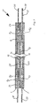
- Figs. 1 and 2 show bipolar or electrode plates (1, 2, 3, 4).
- the electrode plate (1) has metal strips (5 to 9) on, originally from a sheet metal have been punched. In the tin were the metal strips (7, 5, 8, 6, 9) arranged side by side. through a plastic (10) are channels (11, 12, 13) for the Reaction gas or the reaction liquid (not shown here) educated. Between the electrode plate (1) and the electrode plate (2) is a membrane (14) having gas diffusion layers (15, 16) arranged.
- the electrode plates (1, 2) come up with a certain contact pressure the gas diffusion layers (15, 16) pressed.
- Electrode plate based on how the leadership of the reactants in the Channels takes place.
- the channels of Plate (1) that is in the channels (11, 12, 13), for example Hydrogen led while in the channels of the Plate (2) is guided oxygen, it is a Electrode plate.
- a cooling surface (17) is additionally shown.
- Fig. 3 shows an injection mold (18) with inserts (19) in a base and inserts (20) in a top.
- the metal strips (5, 6) are of the lower insert (19) of the injection molding tool (18) to the upper Insert (20) of the injection mold (18) pressed, alike the metal strips (7, 8, 9) are separated from the upper one Insert (20) of the injection mold (18) to the lower Insert (19) pressed.
- the metal strips (5, 6) in turn arranged in the injection mold (18).
- the injection mold (18) is in the embodiment shown in FIG the final position.
- the metal strips (5 to 9) are low Distance to the upper part (20) and the lower part (19) of the injection tool (18) arranged in this.
- the Injection pressure By the Injection pressure, the metal strips (5, 6) to the top (20) and the metal strips (7, 8, 9) to the lower part (19) of the injection mold (18) pressed, so that in turn the electrode plate (1) shown in Fig. 4 is formed becomes.
- Fig. 6 shows a fuel cell (21) with two electrode plates (1, 2).
- the electrode plate (1) has the metal strips (6, 8), which serve as conductor tracks.
- the electrode plate (2) has the conductor tracks (22, 23).
- a plastic seal (24) is molded in the edge region of the fuel cell (21) .
- oxygen (O 2 ) is passed, while through the channels (25) of the electrode plate (2) hydrogen (H 2 ) is passed.
- the gas diffusion layers (15, 16) are arranged with the diaphragm (14) between them.
- the conductor track (23) is encapsulated with plastic (26), which simultaneously forms the channel (25).
- the fuel cell (27) is shown with the electrode plates (1, 2), in turn, the conductor tracks (6, 8, 22, 23). Between the electrode plates (1, 2), the gas diffusion layers (15, 16) are arranged with the diaphragm (14) between them. In the fuel cell (27) shown in Fig. 7 channels (28, 29) are formed. Hydrogen (H 2 ) is passed through channel (28) while oxygen (O 2 ) is passed through channel (29).
- the fuel cell (27) has a plastic seal (24). Protruding metal plates (30) are used for heat dissipation into a non-conductive cooling medium (not shown).
- Fig. 8 is a series circuit of electrode plates shown.
- the electrode plates (1, 2) form a pair as well as the electrode plates (3, 4).
- Conductor tracks for example, contact surfaces (5, 7) in Fig. 2 are electrically isolated from each other.
- You have, however an electrical connection to the next electrode plate of the same electrode pair (1, 2) for example Contact surface (5) with contact surface (23) and contact surface (7) with contact surface (22) in Fig. 2).
- a gas diffusion layer arranged with membrane (32).
- Fig. 9 shows a parallel connection with the electrode plates (1, 2, 3, 4) with the interposed therebetween Gas diffusion layers with membranes (32).
- the two interconnects for example Contact surfaces (5, 7) of FIG. 2) electrically connected.
- the electrode plate pairs (1, 3) are electrically connected to each other connected via the continuous sheet metal strand (31), and the electrode plate pairs (2, 4) are electrically over the continuous sheet metal strand (31) (shown on the right in FIG. 9) connected with each other.
Landscapes
- Chemical & Material Sciences (AREA)
- Engineering & Computer Science (AREA)
- Manufacturing & Machinery (AREA)
- Chemical Kinetics & Catalysis (AREA)
- Sustainable Energy (AREA)
- Sustainable Development (AREA)
- Life Sciences & Earth Sciences (AREA)
- Electrochemistry (AREA)
- General Chemical & Material Sciences (AREA)
- Mechanical Engineering (AREA)
- Composite Materials (AREA)
- Fuel Cell (AREA)
- Electrolytic Production Of Non-Metals, Compounds, Apparatuses Therefor (AREA)
Abstract
Description
- Bei der Bipolarplatte sind der Brennstoff und das Oxidationsmittel durch Kunststoffwände getrennt,
- bei der Elektrodenplatte ist in jeder Einzelzelle zwischen zwei Membran-Elektroden-Einheiten nur ein Medium, nämlich Brennstoff oder Oxidationsmittel vorhanden.
- Fig. 1
- einen Längsschnitt durch einen Stapel von Bipolar- oder Elektrodenplatten;
- Fig. 2
- eine Einzelheit der Fig. 1;
- Fig. 3
- ein Spritzwerkzeug mit in dem Spritzwerkzeug angeordneten Metallstreifen vor dem Spritzvorgang im Querschnitt;
- Fig. 4
- das Spritzwerkzeug gemäß Fig. 3 nach dem Spritzvorgang;
- Fig. 5
- ein Spritzwerkzeug im Querschnitt gemäß einem geänderten Spritzverfahren;
- Fig. 6
- eine Brennstoffzelle mit zwei Elektrodenplatten im Längsschnitt;
- Fig. 7
- eine Brennstoffzelle mit zwei Bipolarplatten im Längsschnitt;
- Fig. 8
- eine Reihenschaltung von Elektrodenplatten;
- Fig. 9
- eine Parallelschaltung von Elektrodenplatten.
- 1 bis 4
- Elektrodenplatten
- 5 bis 9
- Metallstreifen
- 10
- Kunststoff
- 11 bis 13
- Kanäle
- 14
- Membran
- 15, 16
- Gasdiffusionsschichten
- 17
- Kühlfläche
- 18
- Spritzwerkzeug
- 19
- Unterteil von (18)
- 20
- Oberteil von (18)
- 21
- Brennstoffzelle
- 22
- Leiterbahn
- 23
- Leiterbahn
- 24
- Kunststoffdichtung
- 25
- Kanal
- 26
- Kunststoff
- 27
- Brennstoffzelle
- 28
- Kanal
- 29
- Kanal
- 30
- Metallplatten
- 31
- Verbindung Leiterbahnen
- 32
- Gasdiffusionsschicht und Membran
- A
- Pfeil
Claims (22)
- Verfahren zur Herstellung von Bipolar- oder Elektrodenplatten für Brennstoffzellen- oder Elektrolyseur-Stapel,
dadurch gekennzeichnet, dass die Bipolar- oder Elektrodenplatte wenigstens ein Stanzband und/oder wenigstens eine Platine aufweist, die aus einem flächigen Material eines leitfähigen und korrosionsbeständigen Metalles gestanzt wird mit den Verfahrensschritten:das flächige Material wird streifenförmig im Stanzverfahren eingeschnitten,die Streifen werden aus einer Mittellage herausgeschoben,es wird ein Spritzvorgang durchgeführt, derart, dass die Streifen durch Kunststoff gehalten werden. - Verfahren nach Anspruch 1, dadurch gekennzeichnet, dass das wenigstens eine Stanzband und/oder die wenigstens eine Platine mit Kunststoff umspritzt werden, derart, dass mit dem Kunststoff Kanäle für die Durchführung von Reaktionsmitteln ausgebildet werden.
- Verfahren nach einem der vorhergehenden Ansprüche, dadurch gekennzeichnet, dass die Streifen während des Stanzvorganges lediglich teilweise eingeschnitten und/oder Verbindungsstege ausgebildet werden.
- Verfahren nach einem der vorhergehenden Ansprüche, dadurch gekennzeichnet, dass die Streifen während des Spritzvorganges in ihre Endposition verschoben und teilweise umspritzt werden.
- Verfahren nach einem der vorhergehenden Ansprüche, dadurch gekennzeichnet, dass die Streifen durch den Spritzdruck oder durch bewegliche Einsätze (19, 20) des Spritzwerkzeuges während des Spritzvorganges in ihre Endposition gebracht werden.
- Verfahren nach einem der vorhergehenden Ansprüche, dadurch gekennzeichnet, dass in einem Arbeitsbereich der gestanzten Platinen oder Stanzbänder Kanäle zur Führung der Reaktionsmittel vor- oder fertiggeformt werden.
- Verfahren nach einem der vorhergehenden Ansprüche, dadurch gekennzeichnet, dass nach dem Stanzvorgang und vor dem Spritzvorgang eine Oberflächenbehandlung der Platinen oder Stanzbänder durchgeführt wird.
- Verfahren zur Herstellung eines Stapels von Bipolar- oder Elektrodenplatten nach einem der vorhergehenden Ansprüche, dadurch gekennzeichnet, dass zwischen den Platinen und/oder Stanzbändern wenigstens eine Gasdiffusionsschichten tragende Membran angeordnet wird.
- Verfahren nach einem der vorhergehenden Ansprüche, dadurch gekennzeichnet, dass der Verlauf der Kanäle in einem Flow-Field zwischen gegenüberliegenden Plattenebenen parallel angeordnet wird, so dass jeweils zwei sich gegenüberliegende oder kreuzweise geführte, aus dem flächigen Material ausgebildete und mit Kunststoff teilweise umspritzte Metallstreifen mit Druck auf beiden Seiten der die Gasdiffusionsschicht tragenden Membran anliegend angeordnet werden.
- Verfahren nach Anspruch 9, dadurch gekennzeichnet, dass ein Kunststoffrahmen mit Dichtung an die Stanzbänder und/oder Platinen angespritzt wird.
- Verfahren nach einem der Ansprüche 8 bis 10, dadurch gekennzeichnet, dass die Bipolar- oder Elektrodenplatten in dem Stapel in Reihen- und/oder Parallelschaltung angeordnet werden.
- Verfahren nach einem der Ansprüche 8 bis 11, dadurch gekennzeichnet, dass der Stapel durch Aneinanderreihen gleicher Abschnitte aufgebaut wird, wobei ein Abschnitt einer Elektrodenplatte Verteilerkanäle sowie Anschlüsse für die Reaktionsmittel und eine Membran-Elektroden-Einheit (MEA) aufweist, wobei die Membran-Elektroden-Einheit des n-ten Abschnittes die gasdichte und elektrisch isolierende, jedoch protonenleitfähige Begrenzung des (n+1)ten Abschnittes und die Membran-Elektroden-Einheit des (n+1)ten Abschnittes die gasdichte und elektrisch isolierende protonenleitfähige Begrenzung zum (n+2)ten Abschnitt bildet (n = ganze Zahl).
- Verfahren nach einem der Ansprüche 8 bis 11, dadurch gekennzeichnet, dass an beiden Enden des Elektrodenstapels Endplatten angeordnet werden, zwischen denen die einzelnen aneinander gereihten Abschnitte mit ihren Dichtungen eingespannt sind, und die Anschlüsse für das Zu- und Abführen der Reaktionsmittel aufweisen.
- Bipolar- oder Elektrodenplatte, dadurch gekennzeichnet, dass die Bipolar- oder Elektrodenplatte wenigstens ein Stanzband und/oder wenigstens eine Platine mit Streifen aus gestanztem flächigen Material eines leitfähigen und korrosionsbeständigen Metalles aufweist, und dass das wenigstens eine Stanzband oder die wenigstens eine Platine wenigstens teilweise mit Kunststoff umspritzt ausgebildet ist, wobei durch den Kunststoff Kanäle für Reaktionsmittel ausgebildet sind.
- Bipolar- oder Elektrodenplatte nach Anspruch 14, dadurch gekennzeichnet, dass das wenigstens eine Stanzband und/oder die wenigstens eine Platine aus Edelstahl oder Kupfer mit einer Korrosionsschutzschicht gebildet sind.
- Bipolar- oder Elektrodenplatte nach einem der Ansprüche 14 oder 15, dadurch gekennzeichnet, dass die gestanzten Stanzbänder und/oder Platinen Öffnungen zur Durchführung der Reaktionsmittel aufweisen.
- Bipolar- oder Elektrodenplatte nach einem der Ansprüche 14 bis 16, dadurch gekennzeichnet, dass die Metallstreifen als oberflächenbehandelte Metallstreifen ausgebildet sind.
- Bipolar- oder Elektrodenplatte nach einem der Ansprüche 14 bis 17, dadurch gekennzeichnet, dass die Metallstreifen gegen die Reaktionsmittel führenden Kunststoffkanäle isoliert ausgebildet sind.
- Bipolar- oder Elektrodenplatte nach einem der Ansprüche 14 bis 18, dadurch gekennzeichnet, dass als Kunststoff Polyphenylensulfid (PPS) verwendet wird.
- Bipolar- oder Elektrodenplatte nach einem der Ansprüche 14 bis 19, dadurch gekennzeichnet, dass für den Brennstoffzelleneinsatz mit Wasserstoffgas oder verschiedenen geeigneten flüssigen oder gasförmigen Stoffen entsprechende Anschlüsse, Verbindungen und Querschnitte vorgesehen sind.
- Bipolar- oder Elektrodenplatte nach einem der Ansprüche 14 bis 20, dadurch gekennzeichnet, dass Anschlüsse, Verbindungen und Querschnitte für den Einsatz als Elektrolyseur ausgelegt sind.
- Bipolar- oder Elektrodenplatte nach einem der Ansprüche 14 bis 21, dadurch gekennzeichnet, dass ein Hochtemperaturkunststoff vorgesehen ist.
Priority Applications (1)
| Application Number | Priority Date | Filing Date | Title |
|---|---|---|---|
| US10/953,616 US20050058878A1 (en) | 2003-09-17 | 2004-09-16 | Method for the production of bipolar plates or electrode plates for fuel cells or electrolyzer stacks, method for the production of a stack of bipolar plates or electrode plates, as well as a bipolar plate or electrode plate |
Applications Claiming Priority (2)
| Application Number | Priority Date | Filing Date | Title |
|---|---|---|---|
| DE10343267 | 2003-09-17 | ||
| DE10343267 | 2003-09-17 |
Publications (2)
| Publication Number | Publication Date |
|---|---|
| EP1517388A1 true EP1517388A1 (de) | 2005-03-23 |
| EP1517388B1 EP1517388B1 (de) | 2006-12-27 |
Family
ID=34177816
Family Applications (1)
| Application Number | Title | Priority Date | Filing Date |
|---|---|---|---|
| EP04018244A Expired - Lifetime EP1517388B1 (de) | 2003-09-17 | 2004-08-02 | Verfahren zur Herstellung von Bipolarplatten für Brennstoffzellen- oder Elektrolyseur-Stapel, sowie Bipolarplatte |
Country Status (5)
| Country | Link |
|---|---|
| US (1) | US20050058878A1 (de) |
| EP (1) | EP1517388B1 (de) |
| AT (1) | ATE349776T1 (de) |
| DE (1) | DE502004002423D1 (de) |
| ES (1) | ES2276197T3 (de) |
Cited By (5)
| Publication number | Priority date | Publication date | Assignee | Title |
|---|---|---|---|---|
| EP1755187A2 (de) | 2005-08-04 | 2007-02-21 | Hüttenberger Produktionstechnik Martin GmbH | Bipolarplatte oder Elektrodenplatte für Brennstoffzellen oder Elektrolyseur-Stapel sowie ein Verfahren zur Herstellung einer Bipolarplatte oder Elektrodenplatte für Brennstoffzellen oder Elektrolyseur-Stapel |
| DE102012111229A1 (de) * | 2012-11-21 | 2014-05-22 | Eisenhuth Gmbh & Co. Kg | Bipolarplatte für einen PEM-Stapelreaktor |
| DE102007025828B4 (de) * | 2007-06-02 | 2014-09-18 | Michael Martin | Verfahren zur Herstellung von Bipolar- oder Elektrodenplatten für Brennstoffzellen- oder Elektrolyseur-Stapel sowie Verfahren zur Herstellung eines Stapels von Bipolar- oder Elektrodenplatten sowie Bipolar- oder Elektrodenplatte |
| DE102022101106A1 (de) | 2022-01-18 | 2023-07-20 | Pöppelmann Holding GmbH & Co. KG | Elektrolysezelle und Elektrolyseur |
| DE102024118528A1 (de) * | 2024-07-01 | 2026-01-08 | Fraunhofer-Gesellschaft zur Förderung der angewandten Forschung eingetragener Verein | Verfahren und Produktionsvorrichtung zur Herstellung und Bearbeitung von strukturierten Platten und Stapelanordnung von strukturierten Platten |
Families Citing this family (13)
| Publication number | Priority date | Publication date | Assignee | Title |
|---|---|---|---|---|
| US20100216037A1 (en) * | 2006-12-26 | 2010-08-26 | The University Of Akron | Carbon-filled polymer composite bipolar plates for proton exchange membrane fuel cells |
| US9657400B2 (en) * | 2008-06-10 | 2017-05-23 | General Electric Company | Electrolyzer assembly method and system |
| DE102009016635A1 (de) | 2009-04-08 | 2010-10-14 | Elcomax Gmbh | Bipolarplatte für Brennstoff- oder Elektrolysezellen |
| GB2478154B (en) * | 2010-02-26 | 2016-02-24 | Intelligent Energy Ltd | Laminated fuel cell assembly |
| KR20120105331A (ko) * | 2011-03-15 | 2012-09-25 | 현대자동차주식회사 | 내부식성이 향상된 연료전지 스택 |
| US20130034801A1 (en) * | 2011-08-05 | 2013-02-07 | EnerFuel, Inc, | Bipolar plate assembly having an adjustment member |
| DE102013215605A1 (de) * | 2013-08-07 | 2015-02-12 | Bayerische Motoren Werke Aktiengesellschaft | Verfahren zur Herstellung einer Brennstoffzelle und eines Brennstoffzellensystems |
| DE102015111336A1 (de) * | 2015-07-13 | 2017-01-19 | CONTTEK Holding GmbH | Beschichtung von Stanzteilen mithilfe von Plasma-Beschichtungsverfahren |
| DE102018220464A1 (de) * | 2018-11-28 | 2020-05-28 | Robert Bosch Gmbh | Verteilerstruktur für Brennstoffzelle und Elektrolyseur |
| DE102020212744A1 (de) * | 2020-10-08 | 2022-04-14 | Robert Bosch Gesellschaft mit beschränkter Haftung | Zellstapel und dessen Herstellung |
| DE102020216095A1 (de) * | 2020-12-17 | 2022-06-23 | Robert Bosch Gesellschaft mit beschränkter Haftung | Bipolarplatte, elektrochemische Zelle und Verfahren zum Herstellen einer elektrochemischen Zelle |
| JP2025536080A (ja) * | 2022-11-28 | 2025-10-30 | エルジー・ケム・リミテッド | 電気分解装置 |
| CN118492203A (zh) * | 2024-04-10 | 2024-08-16 | 东北大学 | 高温合金双极板的成形方法及系统 |
Citations (5)
| Publication number | Priority date | Publication date | Assignee | Title |
|---|---|---|---|---|
| US6071635A (en) * | 1998-04-03 | 2000-06-06 | Plug Power, L.L.C. | Easily-formable fuel cell assembly fluid flow plate having conductivity and increased non-conductive material |
| US6096450A (en) * | 1998-02-11 | 2000-08-01 | Plug Power Inc. | Fuel cell assembly fluid flow plate having conductive fibers and rigidizing material therein |
| EP1035608A2 (de) * | 1999-02-09 | 2000-09-13 | Nisshinbo Industries, Inc. | Separator für Brennstoffzellen und Festelektrolytbrennstoffzellen mit diesem Separator |
| FR2810795A1 (fr) * | 2000-06-27 | 2001-12-28 | Technicatome | Plaque bipolaire a deux plaques metalliques pour pile a combustible et son procede de fabrication |
| DE10112394A1 (de) * | 2001-03-13 | 2002-10-02 | Ticona Gmbh | Leitfähige Kunststofformmasse, ihre Verwendung und daraus hergestellte Formkörper |
Family Cites Families (7)
| Publication number | Priority date | Publication date | Assignee | Title |
|---|---|---|---|---|
| US5114807A (en) * | 1990-04-30 | 1992-05-19 | California Institute Of Technology | Lightweight bipolar storage battery |
| US7098163B2 (en) * | 1998-08-27 | 2006-08-29 | Cabot Corporation | Method of producing membrane electrode assemblies for use in proton exchange membrane and direct methanol fuel cells |
| DE19910487C1 (de) * | 1999-03-10 | 2000-06-15 | Freudenberg Carl Fa | Verfahren und Werkzeug zur Herstellung von Bipolarplatten |
| US6322919B1 (en) * | 1999-08-16 | 2001-11-27 | Alliedsignal Inc. | Fuel cell and bipolar plate for use with same |
| JP3400415B2 (ja) * | 2000-07-25 | 2003-04-28 | 本田技研工業株式会社 | 燃料電池のシール構造 |
| US6677071B2 (en) * | 2001-02-15 | 2004-01-13 | Asia Pacific Fuel Cell Technologies, Ltd. | Bipolar plate for a fuel cell |
| US6864004B2 (en) * | 2003-04-03 | 2005-03-08 | The Regents Of The University Of California | Direct methanol fuel cell stack |
-
2004
- 2004-08-02 DE DE502004002423T patent/DE502004002423D1/de not_active Expired - Lifetime
- 2004-08-02 EP EP04018244A patent/EP1517388B1/de not_active Expired - Lifetime
- 2004-08-02 AT AT04018244T patent/ATE349776T1/de active
- 2004-08-02 ES ES04018244T patent/ES2276197T3/es not_active Expired - Lifetime
- 2004-09-16 US US10/953,616 patent/US20050058878A1/en not_active Abandoned
Patent Citations (5)
| Publication number | Priority date | Publication date | Assignee | Title |
|---|---|---|---|---|
| US6096450A (en) * | 1998-02-11 | 2000-08-01 | Plug Power Inc. | Fuel cell assembly fluid flow plate having conductive fibers and rigidizing material therein |
| US6071635A (en) * | 1998-04-03 | 2000-06-06 | Plug Power, L.L.C. | Easily-formable fuel cell assembly fluid flow plate having conductivity and increased non-conductive material |
| EP1035608A2 (de) * | 1999-02-09 | 2000-09-13 | Nisshinbo Industries, Inc. | Separator für Brennstoffzellen und Festelektrolytbrennstoffzellen mit diesem Separator |
| FR2810795A1 (fr) * | 2000-06-27 | 2001-12-28 | Technicatome | Plaque bipolaire a deux plaques metalliques pour pile a combustible et son procede de fabrication |
| DE10112394A1 (de) * | 2001-03-13 | 2002-10-02 | Ticona Gmbh | Leitfähige Kunststofformmasse, ihre Verwendung und daraus hergestellte Formkörper |
Cited By (7)
| Publication number | Priority date | Publication date | Assignee | Title |
|---|---|---|---|---|
| EP1755187A2 (de) | 2005-08-04 | 2007-02-21 | Hüttenberger Produktionstechnik Martin GmbH | Bipolarplatte oder Elektrodenplatte für Brennstoffzellen oder Elektrolyseur-Stapel sowie ein Verfahren zur Herstellung einer Bipolarplatte oder Elektrodenplatte für Brennstoffzellen oder Elektrolyseur-Stapel |
| EP1755187A3 (de) * | 2005-08-04 | 2009-01-21 | Hüttenberger Produktionstechnik Martin GmbH | Bipolarplatte oder Elektrodenplatte für Brennstoffzellen oder Elektrolyseur-Stapel sowie ein Verfahren zur Herstellung einer Bipolarplatte oder Elektrodenplatte für Brennstoffzellen oder Elektrolyseur-Stapel |
| DE102007025828B4 (de) * | 2007-06-02 | 2014-09-18 | Michael Martin | Verfahren zur Herstellung von Bipolar- oder Elektrodenplatten für Brennstoffzellen- oder Elektrolyseur-Stapel sowie Verfahren zur Herstellung eines Stapels von Bipolar- oder Elektrodenplatten sowie Bipolar- oder Elektrodenplatte |
| DE102012111229A1 (de) * | 2012-11-21 | 2014-05-22 | Eisenhuth Gmbh & Co. Kg | Bipolarplatte für einen PEM-Stapelreaktor |
| DE102012111229B4 (de) | 2012-11-21 | 2019-06-13 | Eisenhuth Gmbh & Co. Kg | Bipolarplatte für einen PEM-Stapelreaktor und PEM-Stapelreaktor |
| DE102022101106A1 (de) | 2022-01-18 | 2023-07-20 | Pöppelmann Holding GmbH & Co. KG | Elektrolysezelle und Elektrolyseur |
| DE102024118528A1 (de) * | 2024-07-01 | 2026-01-08 | Fraunhofer-Gesellschaft zur Förderung der angewandten Forschung eingetragener Verein | Verfahren und Produktionsvorrichtung zur Herstellung und Bearbeitung von strukturierten Platten und Stapelanordnung von strukturierten Platten |
Also Published As
| Publication number | Publication date |
|---|---|
| US20050058878A1 (en) | 2005-03-17 |
| ATE349776T1 (de) | 2007-01-15 |
| DE502004002423D1 (de) | 2007-02-08 |
| EP1517388B1 (de) | 2006-12-27 |
| ES2276197T3 (es) | 2007-06-16 |
Similar Documents
| Publication | Publication Date | Title |
|---|---|---|
| EP1517388B1 (de) | Verfahren zur Herstellung von Bipolarplatten für Brennstoffzellen- oder Elektrolyseur-Stapel, sowie Bipolarplatte | |
| DE102009006413B4 (de) | Bipolarplatte mit einer Wulstdichtung sowie Brennstoffzelle mit solch einer Bipolarplatte | |
| DE10226962B4 (de) | Brennstoffzelle | |
| EP2912711B1 (de) | Membran-elektroden-anordnung sowie brennstoffzelle mit einer solchen | |
| DE102004041670B4 (de) | Brennstoffzelle | |
| DE10225210B4 (de) | Dichtungsstruktur einer Brennstoffzelle | |
| EP2912712B1 (de) | Membran-elektroden-anordnung, brennstoffzelle mit einer solchen und kraftfahrzeug mit der brennstoffzelle | |
| DE10109654A1 (de) | Brennstoffzelle | |
| DE10340215A1 (de) | Polymerelektrolytmembran-Brennstoffzelle und bipolare Platte | |
| DE102009016635A1 (de) | Bipolarplatte für Brennstoff- oder Elektrolysezellen | |
| DE202014007977U1 (de) | Elektrochemisches System | |
| DE102017201644A1 (de) | Verfahren zur herstellung eines brennstoffzellenstapels und verfahren zur herstellung eines metallseparators für eine brennstoffzelle | |
| DE102005056341B4 (de) | Brennstoffzelle | |
| DE102012111229B4 (de) | Bipolarplatte für einen PEM-Stapelreaktor und PEM-Stapelreaktor | |
| EP1653538A1 (de) | Kühlplattenmodul mit integralem Dichtungselement für einen Brennstoffzellenstack | |
| DE10158771A1 (de) | Brennstoffzellensystem | |
| WO2015120933A1 (de) | Bipolarplatte, brennstoffzelle und kraftfahrzeug sowie verfahren zur herstellung der bipolarplatte | |
| DE102007025828B4 (de) | Verfahren zur Herstellung von Bipolar- oder Elektrodenplatten für Brennstoffzellen- oder Elektrolyseur-Stapel sowie Verfahren zur Herstellung eines Stapels von Bipolar- oder Elektrodenplatten sowie Bipolar- oder Elektrodenplatte | |
| DE1596016A1 (de) | Zusammengesetzte Hohlelektrode fuer Brennstoffzellen und durch Zusammenbau solcher Elektroden hergestellte Brennstoffzellen | |
| DE10226388A1 (de) | Separator für Brennstoffzelle | |
| DE102005037345A1 (de) | Bipolarplatte für Brennstoffzellen oder Elektrolyseur-Stapel sowie ein Verfahren zur Herstellung einer Bipolarplatte für Brennstoffzellen oder Elektrolyseur-Stapel | |
| DE60306916T2 (de) | Elektrochemischer generator mit einer bipolarplatte, welche eine vielzahl von der verteilung der gase dienenden löchern aufweist | |
| DE102006056468A1 (de) | Bipolarplatte, insbesondere für einen Brennstoffzellenstapel eines Fahrzeugs | |
| DE60303459T2 (de) | Elektrochemischer membrangenerator | |
| EP1796196A2 (de) | Bipolarplatte, insbesondere für einen Brennstoffzellenstapel eines Fahrzeugs |
Legal Events
| Date | Code | Title | Description |
|---|---|---|---|
| PUAI | Public reference made under article 153(3) epc to a published international application that has entered the european phase |
Free format text: ORIGINAL CODE: 0009012 |
|
| AK | Designated contracting states |
Kind code of ref document: A1 Designated state(s): AT BE BG CH CY CZ DE DK EE ES FI FR GB GR HU IE IT LI LU MC NL PL PT RO SE SI SK TR |
|
| AX | Request for extension of the european patent |
Extension state: AL HR LT LV MK |
|
| 17P | Request for examination filed |
Effective date: 20050621 |
|
| AKX | Designation fees paid |
Designated state(s): AT BE BG CH CY CZ DE DK EE ES FI FR GB GR HU IE IT LI LU MC NL PL PT RO SE SI SK TR |
|
| GRAP | Despatch of communication of intention to grant a patent |
Free format text: ORIGINAL CODE: EPIDOSNIGR1 |
|
| GRAS | Grant fee paid |
Free format text: ORIGINAL CODE: EPIDOSNIGR3 |
|
| GRAA | (expected) grant |
Free format text: ORIGINAL CODE: 0009210 |
|
| AK | Designated contracting states |
Kind code of ref document: B1 Designated state(s): AT BE BG CH CY CZ DE DK EE ES FI FR GB GR HU IE IT LI LU MC NL PL PT RO SE SI SK TR |
|
| PG25 | Lapsed in a contracting state [announced via postgrant information from national office to epo] |
Ref country code: DK Free format text: LAPSE BECAUSE OF FAILURE TO SUBMIT A TRANSLATION OF THE DESCRIPTION OR TO PAY THE FEE WITHIN THE PRESCRIBED TIME-LIMIT Effective date: 20061227 Ref country code: PL Free format text: LAPSE BECAUSE OF FAILURE TO SUBMIT A TRANSLATION OF THE DESCRIPTION OR TO PAY THE FEE WITHIN THE PRESCRIBED TIME-LIMIT Effective date: 20061227 Ref country code: FI Free format text: LAPSE BECAUSE OF FAILURE TO SUBMIT A TRANSLATION OF THE DESCRIPTION OR TO PAY THE FEE WITHIN THE PRESCRIBED TIME-LIMIT Effective date: 20061227 Ref country code: SI Free format text: LAPSE BECAUSE OF FAILURE TO SUBMIT A TRANSLATION OF THE DESCRIPTION OR TO PAY THE FEE WITHIN THE PRESCRIBED TIME-LIMIT Effective date: 20061227 Ref country code: RO Free format text: LAPSE BECAUSE OF FAILURE TO SUBMIT A TRANSLATION OF THE DESCRIPTION OR TO PAY THE FEE WITHIN THE PRESCRIBED TIME-LIMIT Effective date: 20061227 Ref country code: CZ Free format text: LAPSE BECAUSE OF FAILURE TO SUBMIT A TRANSLATION OF THE DESCRIPTION OR TO PAY THE FEE WITHIN THE PRESCRIBED TIME-LIMIT Effective date: 20061227 Ref country code: SK Free format text: LAPSE BECAUSE OF FAILURE TO SUBMIT A TRANSLATION OF THE DESCRIPTION OR TO PAY THE FEE WITHIN THE PRESCRIBED TIME-LIMIT Effective date: 20061227 Ref country code: IE Free format text: LAPSE BECAUSE OF FAILURE TO SUBMIT A TRANSLATION OF THE DESCRIPTION OR TO PAY THE FEE WITHIN THE PRESCRIBED TIME-LIMIT Effective date: 20061227 |
|
| REG | Reference to a national code |
Ref country code: GB Ref legal event code: FG4D Free format text: NOT ENGLISH |
|
| REG | Reference to a national code |
Ref country code: IE Ref legal event code: FG4D Free format text: LANGUAGE OF EP DOCUMENT: GERMAN |
|
| REF | Corresponds to: |
Ref document number: 502004002423 Country of ref document: DE Date of ref document: 20070208 Kind code of ref document: P |
|
| REG | Reference to a national code |
Ref country code: GR Ref legal event code: EP Ref document number: 20070400162 Country of ref document: GR |
|
| PG25 | Lapsed in a contracting state [announced via postgrant information from national office to epo] |
Ref country code: BG Free format text: LAPSE BECAUSE OF FAILURE TO SUBMIT A TRANSLATION OF THE DESCRIPTION OR TO PAY THE FEE WITHIN THE PRESCRIBED TIME-LIMIT Effective date: 20070327 Ref country code: SE Free format text: LAPSE BECAUSE OF FAILURE TO SUBMIT A TRANSLATION OF THE DESCRIPTION OR TO PAY THE FEE WITHIN THE PRESCRIBED TIME-LIMIT Effective date: 20070327 |
|
| GBT | Gb: translation of ep patent filed (gb section 77(6)(a)/1977) |
Effective date: 20070319 |
|
| PG25 | Lapsed in a contracting state [announced via postgrant information from national office to epo] |
Ref country code: PT Free format text: LAPSE BECAUSE OF FAILURE TO SUBMIT A TRANSLATION OF THE DESCRIPTION OR TO PAY THE FEE WITHIN THE PRESCRIBED TIME-LIMIT Effective date: 20070528 |
|
| REG | Reference to a national code |
Ref country code: ES Ref legal event code: FG2A Ref document number: 2276197 Country of ref document: ES Kind code of ref document: T3 |
|
| ET | Fr: translation filed | ||
| PLBE | No opposition filed within time limit |
Free format text: ORIGINAL CODE: 0009261 |
|
| STAA | Information on the status of an ep patent application or granted ep patent |
Free format text: STATUS: NO OPPOSITION FILED WITHIN TIME LIMIT |
|
| 26N | No opposition filed |
Effective date: 20070928 |
|
| BERE | Be: lapsed |
Owner name: HUTTENBERGER PRODUKTIONSTECHNIK MARTIN G.M.B.H. Effective date: 20070831 |
|
| PG25 | Lapsed in a contracting state [announced via postgrant information from national office to epo] |
Ref country code: MC Free format text: LAPSE BECAUSE OF NON-PAYMENT OF DUE FEES Effective date: 20070831 |
|
| PG25 | Lapsed in a contracting state [announced via postgrant information from national office to epo] |
Ref country code: BE Free format text: LAPSE BECAUSE OF NON-PAYMENT OF DUE FEES Effective date: 20070831 |
|
| PG25 | Lapsed in a contracting state [announced via postgrant information from national office to epo] |
Ref country code: EE Free format text: LAPSE BECAUSE OF FAILURE TO SUBMIT A TRANSLATION OF THE DESCRIPTION OR TO PAY THE FEE WITHIN THE PRESCRIBED TIME-LIMIT Effective date: 20061227 |
|
| PG25 | Lapsed in a contracting state [announced via postgrant information from national office to epo] |
Ref country code: LU Free format text: LAPSE BECAUSE OF NON-PAYMENT OF DUE FEES Effective date: 20070802 Ref country code: CY Free format text: LAPSE BECAUSE OF FAILURE TO SUBMIT A TRANSLATION OF THE DESCRIPTION OR TO PAY THE FEE WITHIN THE PRESCRIBED TIME-LIMIT Effective date: 20061227 |
|
| PG25 | Lapsed in a contracting state [announced via postgrant information from national office to epo] |
Ref country code: TR Free format text: LAPSE BECAUSE OF FAILURE TO SUBMIT A TRANSLATION OF THE DESCRIPTION OR TO PAY THE FEE WITHIN THE PRESCRIBED TIME-LIMIT Effective date: 20061227 Ref country code: HU Free format text: LAPSE BECAUSE OF FAILURE TO SUBMIT A TRANSLATION OF THE DESCRIPTION OR TO PAY THE FEE WITHIN THE PRESCRIBED TIME-LIMIT Effective date: 20070628 |
|
| REG | Reference to a national code |
Ref country code: CH Ref legal event code: PFA Owner name: HUETTENBERGER PRODUKTIONSTECHNIK MARTIN GMBH Free format text: HUETTENBERGER PRODUKTIONSTECHNIK MARTIN GMBH#AM WINGERT 12#35428 LANGGOENS (DE) -TRANSFER TO- HUETTENBERGER PRODUKTIONSTECHNIK MARTIN GMBH#AM WINGERT 12#35428 LANGGOENS (DE) |
|
| PGFP | Annual fee paid to national office [announced via postgrant information from national office to epo] |
Ref country code: GR Payment date: 20140827 Year of fee payment: 11 Ref country code: DE Payment date: 20140718 Year of fee payment: 11 Ref country code: CH Payment date: 20140820 Year of fee payment: 11 Ref country code: NL Payment date: 20140820 Year of fee payment: 11 |
|
| PGFP | Annual fee paid to national office [announced via postgrant information from national office to epo] |
Ref country code: FR Payment date: 20140821 Year of fee payment: 11 Ref country code: GB Payment date: 20140820 Year of fee payment: 11 Ref country code: ES Payment date: 20140826 Year of fee payment: 11 Ref country code: AT Payment date: 20140813 Year of fee payment: 11 |
|
| PGFP | Annual fee paid to national office [announced via postgrant information from national office to epo] |
Ref country code: IT Payment date: 20140827 Year of fee payment: 11 |
|
| REG | Reference to a national code |
Ref country code: DE Ref legal event code: R119 Ref document number: 502004002423 Country of ref document: DE |
|
| REG | Reference to a national code |
Ref country code: CH Ref legal event code: PL |
|
| REG | Reference to a national code |
Ref country code: AT Ref legal event code: MM01 Ref document number: 349776 Country of ref document: AT Kind code of ref document: T Effective date: 20150802 |
|
| GBPC | Gb: european patent ceased through non-payment of renewal fee |
Effective date: 20150802 |
|
| PG25 | Lapsed in a contracting state [announced via postgrant information from national office to epo] |
Ref country code: IT Free format text: LAPSE BECAUSE OF NON-PAYMENT OF DUE FEES Effective date: 20150802 Ref country code: CH Free format text: LAPSE BECAUSE OF NON-PAYMENT OF DUE FEES Effective date: 20150831 Ref country code: LI Free format text: LAPSE BECAUSE OF NON-PAYMENT OF DUE FEES Effective date: 20150831 |
|
| REG | Reference to a national code |
Ref country code: NL Ref legal event code: MM Effective date: 20150901 |
|
| PG25 | Lapsed in a contracting state [announced via postgrant information from national office to epo] |
Ref country code: GR Free format text: LAPSE BECAUSE OF NON-PAYMENT OF DUE FEES Effective date: 20160303 Ref country code: AT Free format text: LAPSE BECAUSE OF NON-PAYMENT OF DUE FEES Effective date: 20150802 |
|
| REG | Reference to a national code |
Ref country code: FR Ref legal event code: ST Effective date: 20160429 |
|
| REG | Reference to a national code |
Ref country code: GR Ref legal event code: ML Ref document number: 20070400162 Country of ref document: GR Effective date: 20160303 |
|
| PG25 | Lapsed in a contracting state [announced via postgrant information from national office to epo] |
Ref country code: NL Free format text: LAPSE BECAUSE OF NON-PAYMENT OF DUE FEES Effective date: 20150901 |
|
| PG25 | Lapsed in a contracting state [announced via postgrant information from national office to epo] |
Ref country code: GB Free format text: LAPSE BECAUSE OF NON-PAYMENT OF DUE FEES Effective date: 20150802 Ref country code: DE Free format text: LAPSE BECAUSE OF NON-PAYMENT OF DUE FEES Effective date: 20160301 |
|
| PG25 | Lapsed in a contracting state [announced via postgrant information from national office to epo] |
Ref country code: FR Free format text: LAPSE BECAUSE OF NON-PAYMENT OF DUE FEES Effective date: 20150831 |
|
| REG | Reference to a national code |
Ref country code: ES Ref legal event code: FD2A Effective date: 20160927 |
|
| PG25 | Lapsed in a contracting state [announced via postgrant information from national office to epo] |
Ref country code: ES Free format text: LAPSE BECAUSE OF NON-PAYMENT OF DUE FEES Effective date: 20150803 |