EP1517221A2 - Ensemnle électronique comportant un boítier avec une partie pivotable - Google Patents
Ensemnle électronique comportant un boítier avec une partie pivotable Download PDFInfo
- Publication number
- EP1517221A2 EP1517221A2 EP04255460A EP04255460A EP1517221A2 EP 1517221 A2 EP1517221 A2 EP 1517221A2 EP 04255460 A EP04255460 A EP 04255460A EP 04255460 A EP04255460 A EP 04255460A EP 1517221 A2 EP1517221 A2 EP 1517221A2
- Authority
- EP
- European Patent Office
- Prior art keywords
- housing
- electronic assembly
- recited
- component
- rotated
- Prior art date
- Legal status (The legal status is an assumption and is not a legal conclusion. Google has not performed a legal analysis and makes no representation as to the accuracy of the status listed.)
- Granted
Links
Images



Classifications
-
- G—PHYSICS
- G06—COMPUTING OR CALCULATING; COUNTING
- G06F—ELECTRIC DIGITAL DATA PROCESSING
- G06F1/00—Details not covered by groups G06F3/00 - G06F13/00 and G06F21/00
- G06F1/16—Constructional details or arrangements
- G06F1/18—Packaging or power distribution
- G06F1/183—Internal mounting support structures, e.g. for supporting printed circuit boards
- G06F1/184—Mounting of motherboards
-
- G—PHYSICS
- G06—COMPUTING OR CALCULATING; COUNTING
- G06F—ELECTRIC DIGITAL DATA PROCESSING
- G06F1/00—Details not covered by groups G06F3/00 - G06F13/00 and G06F21/00
- G06F1/16—Constructional details or arrangements
- G06F1/18—Packaging or power distribution
- G06F1/183—Internal mounting support structures, e.g. for supporting printed circuit boards
- G06F1/187—Mounting of fixed or removable disk drives
Definitions
- This invention relates to computer system components and, more particularly, to electronic assembly housings.
- Many computer systems include components or electronic assemblies that include a housing or enclosure. During system maintenance, a given component may be serviced by removing one or more covers.
- a failing component may be serviced either with little effort or in some cases, great difficulty.
- individual internal components such as a memory module or processor, for example, within a failing component enclosure may need to be serviced or replaced.
- many internal components are difficult to access and even more difficult to remove. This may be true even in some high reliability, accessibility and serviceability (RAS) systems.
- RAS accessibility and serviceability
- working internal components may be damaged in an effort to remove or access other non-working internal components.
- An aspect of the invention provides an electronic assembly comprising: a housing including a first portion having a surface forming an outer wall of said housing, wherein said first portion of said housing is rotatably attached to a remaining portion of said housing; a component mounted on said first portion of said housing; and at least one additional component mounted on said remaining portion of said housing; wherein when said first portion of said housing is rotated into a closed position, said component and said at least one additional component are positioned adjacent to each other; and wherein when said first portion of said housing is rotated into an open position, said component and said at least one additional component are moved away from each other to allow access to said at least one additional component.
- Another aspect of the invention provides an old computer system comprising: an equipment rack; one or more electronic assemblies each configured to mount within said equipment rack, wherein each of said one or more electronic assemblies includes: a housing including a first portion having a surface forming an outer wall of said housing, wherein said first portion of said housing is rotatably attached to a remaining portion of said housing; a component mounted on said first portion of said housing; and at least one additional component mounted on said remaining portion of said housing; wherein when said first portion of said housing is rotated into a closed position, said component and said at least one additional component are positioned adjacent to each other; and wherein when said first portion of said housing is rotated into an open position, said component and said at least one additional component are moved away from each other to allow access to said at least one additional component.
- the electronic assembly includes a housing including a first portion and a remaining portion.
- the first portion includes a surface forming an outer wall of the housing.
- the electronic assembly also includes a component such as a compact disk read only memory (CD ROM) drive, for example, that may be mounted on the first portion of the housing.
- CD ROM compact disk read only memory
- at least one additional component such as a motherboard, for example, may be mounted on the remaining portion of the housing.
- the first portion of the housing is rotatably attached to the remaining portion of the housing. When the first portion of the housing is rotated into a closed position, the component and the additional component are positioned adjacent to each other. However, when the first portion of the housing is rotated into an open position, the component and the additional component are moved away from each other to allow access to the additional component.
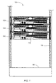
- Computer system 10 includes a system cabinet 100 which houses an equipment rack 110.
- Equipment rack 110 is configured to receive a plurality of electronic assemblies such as rack-mountable components 150A-150C. It is noted that in various other embodiments, system cabinet 100 may be optional. In such embodiments, equipment rack 110 may be a freestanding unit. It is noted that components having a reference number followed by a letter may be referenced by the reference number alone, where appropriate, for simplicity.
- computer system 10 may be a server system.
- a portion of rack-mountable components 150A-C may be configured as individual server units.
- computer system 10 may be any type of computer system.
- each of rack mountable components 150A-C may include a housing (not shown in FIG. 1) that provides a full or partial enclosure and mounting surfaces for various internal components.
- one or more of rack-mountable components 150 may include internal components (not shown in FIG.
- a motherboard such as a motherboard that may include one or more processors, one or more hard disk drives, a compact disk (CD) and or a digital video disk (DVD) drive and one or more conventional input/output (I/O) buses such as a peripheral component interconnect (PCI) bus, for example.
- processors such as a central processing unit (CPU)
- CD compact disk
- DVD digital video disk
- I/O input/output
- PCI peripheral component interconnect
- a given rack-mountable component 150 may be slidably mounted within the equipment rack 110.
- equipment rack 110 may include a backplane (not shown) configured to proved electrical connections to each rack-mountable component 150 when it is inserted into its shelf.
- appropriate cabling (not shown) may be used to interconnect rack-mountable components 150.
- the rack-mountable component 150 may be slid out of equipment rack 110.
- a top panel (not shown in FIG. 1) of the rack-mountable component 150 may be removed and stowed.
- a portion of the housing which includes a surface 175C that forms an outer wall of the rack-mountable component 150C, may be unfastened and rotated out of the way to provide access to internal components such as the motherboard, for example.
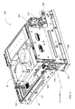
- FIG. 2 a perspective view drawing of one embodiment of the computer system of FIG. 1 is shown. Components corresponding to those shown in FIG. 1-FIG. 3 are numbered identically for clarity and simplicity.
- Rack-mountable component 150C is slidably extended out from equipment rack 110. In this position, slide mount 225 is shown attached to one side of rack-mountable component 150C. An additional slide mount (not shown) may also be attached to the right side of rack-mountable component 150C. Further, in the illustrated embodiment, the housing of rack-mountable component 150C includes a top panel 235.
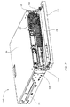
- FIG. 3 a perspective view drawing of one embodiment of a rack-mountable component with its top panel removed is shown.
- Rack-mountable component 150 includes a housing 325 and various internal components.
- Housing 325 includes a rotating portion 325B that includes surface 175 and a remaining portion 325A. It is noted that rotating portion 325B is shown in the closed or non-rotated position.
- housing 325 may be a metallic material that may provide a rigid, ruggedized enclosure that may also provide electromagnetic interference (EMI) protection. However, it is contemplated that in other embodiments, housing 325 may be made from non-metallic materials.
- EMI electromagnetic interference
- an air duct 350 and a motherboard 375 are mounted to remaining portion 325A.
- surface 175C which forms the front outer wall of housing 325, also includes a bezel 310.
- bezel 310 includes a plurality of air inlet holes 311 that may allow cooling air to pass though bezel 310 and into housing 325 during operation.
- bezel 310 may be made from plastic or other non-metallic materials.
- the rotating portion 325B may also have internal components mounted to it.
- a CD ROM drive access door 380 is shown in FIG. 3.
- a CD ROM drive is mounted to the rotating portion 325B.
- rotating portion 325B when the rotating portion 325B is in the closed position, the internal components (e.g., CD ROM drive) that are mounted to the rotating portion 325B are adjacent to the components mounted to the remaining portion 325A of housing 325. In this closed position, rotating portion 325B may partially or completely obscure the components (e.g., motherboard 375 and air duct 350) mounted to remaining portion 325A and the internal components (e.g., CD ROM drive) that are mounted to the rotating portion 325B; thereby making it difficult or impossible to access any of the internal components.
- the internal components e.g., CD ROM drive
- FIG. 4 a perspective view drawing of the rack-mountable component of FIG. 3 is shown. Components corresponding to those shown in FIG. 1-FIG. 3 are numbered identically for clarity and simplicity.
- top panel 235 (not shown in FIG. 4) of rack-mountable component 150 is removed and rotating portion 325B is partially rotated. It is noted that as rotating portion 325B is rotated away from remaining portion 325A, the internal components (e.g., motherboard 375 and air duct 350) mounted to remaining portion 325A and the internal components (e.g., CD ROM drive 485) that are mounted to the rotating portion 325B are becoming accessible.
- the internal components e.g., motherboard 375 and air duct 350
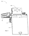
- FIG. 5 another perspective view drawing of the rack-mountable component of FIG. 3 is shown. Components corresponding to those shown in FIG. 1-FIG. 4 are numbered identically for clarity and simplicity.
- top panel 235 (not shown in FIG. 5) rack-mountable component 150 is removed and the rotatable portion 325B is fully rotated to an open position.
- rotatable portion 325B is rotatably attached to remaining portion 325A by a hinge 510A and a hinge 510B.
- other types of mechanisms may be used to rotatably attach rotatable portion 325B to remaining portion 325A.
- hinge 510 causes rotatable portion 325B to rotate about an axis of rotation that allows rotatable portion 325B to rotate down substantially 90 degrees.
- a the hinging mechanism may be attached to allow rotatable portion 325B to be rotated up substantially 90 degrees.
- the hinging mechanism (not shown) may be attached such that the axis of rotation may allow rotatable portion 325B to be rotated right or left substantially 90 degrees. It is noted that in other embodiments, it is contemplated that when in an open position, rotatable portion 325B may rotate to angles other than 90 degrees.
- rack-mountable component 150 includes a fastening mechanism 590 that secures rotatable portion 325B to remaining portion 325A when rotatable portion 325B is in the closed position.
- Fastening mechanism 590 includes a pair of quarter-turn fasteners 590B and 590D that mate with a respective pair of quarter-turn receivers 590A and 590C. It is noted that in other embodiments, other types of fasteners may be used.
- FIG. 6 a top view drawing of the rack-mountable component of FIG. 3 is shown. Components corresponding to those shown in FIG. 1-FIG. 5 are numbered identically for clarity and simplicity.
- top panel 235 (not shown in FIG. 6) of rack-mountable component 150 is removed and rotatable portion 325B is fully rotated to the open position allowing access and visibility to the various internal components.
- rotatable portion 325B may also include other components such as hard disk drives 685A and 685B and a card reader unit 695.
- rack-mountable component 150 includes an air-moving device 610 that includes a pair of blower fans and a pair of corresponding output ports designated 620A and 620B.
- air moving 610 device may include one or more a blower fans.
- air duct 350 includes an air intake port designated 650.
- output ports 620A and 620B line up with and mate to air intake port 650.
- air-moving device 610 draws cooling air through both the air intake holes 311 in bezel 310 and the air intake holes 612 located in front surface 175 and forces the cooling air into air duct 350 through air intake port 650.
- This flow of cooling air is designed to cool one or more processors (not shown) that may be mounted to motherboard 375 and positioned under air duct 350.
- air duct 350 may be removed to allow access to the processors.
- FIG. 7 another perspective view drawing of the rack-mountable component of FIG. 3 is shown. Components corresponding to those shown in FIG. 1-FIG. 6 are numbered identically for clarity and simplicity.
- bezel 310 is rotated into an open position.
- bezel 310 includes a removable air filter 710 that is positioned between air intake holes 311 and air intake holes 612 located in front surface 175. Rotating bezel 310 to the open position may allow access to air filter 710.
- bezel 310 is rotatably attached to rotatable portion 325B using a pair of hinge mechanisms designated 750A and 750B. Although it is contemplated that in other embodiments, different mechanisms may be used to rotatably attach bezel 310 to rotatable portion 325B.
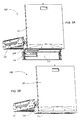
- FIG. 9A and FIG. 9B perspective view drawings of the rack-mountable component of FIG. 3 are shown. Components corresponding to those shown in FIG. 1-FIG. 7 are numbered identically for clarity and simplicity.
- top panel 235 of housing 325 is removed, rotatable portion 325B is rotated into an open position, bezel 310 is rotated into an open position and the top panel is stowed in a down position.
- top panel 235 is stowed using a pin and slot mechanism 890.
- top panel 235 of housing 325 is removed, rotatable portion 325B is rotated into an open position, bezel 310 is rotated into an open position and the top panel is stowed in an up position using the pin and slot stowing mechanism.
- top panel 235 of housing 325 is removed, rotatable portion 325B is rotated into an open position, bezel 310 is rotated into a closed position and the top panel is stowed in an up position using the pin and slot stowing mechanism.
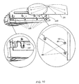
- Top panel 235 includes several stowage pins 890.
- Each stowage pin 890 includes a cylindrical body 891 with a flanged end 892.
- Stowage pins 890 are configured to slidably inset into respective stowage slots 1050 positioned on rotatable portion 325B.
- Each stowage slot 1050 is tapered and includes a lip 1051 configured to capture flanged end 892 of each stowage pin 890.
- lip 1051 holds flange end 892 from pulling out and gravity tends to keep top panel 235 in place.
- any electronic assembly including a stand-alone computer system or module may include the features described above in conjunction with the descriptions of FIG. 1-10.
- any electronic assembly may include a housing having a rotatable portion and a remaining portion, where, in an open position, the rotatable portion may provide access to internal components that are usually obscured in a closed position.
Landscapes
- Engineering & Computer Science (AREA)
- Theoretical Computer Science (AREA)
- Computer Hardware Design (AREA)
- Power Engineering (AREA)
- Human Computer Interaction (AREA)
- Physics & Mathematics (AREA)
- General Engineering & Computer Science (AREA)
- General Physics & Mathematics (AREA)
- Cooling Or The Like Of Electrical Apparatus (AREA)
- Casings For Electric Apparatus (AREA)
Applications Claiming Priority (2)
| Application Number | Priority Date | Filing Date | Title |
|---|---|---|---|
| US668083 | 2003-09-22 | ||
| US10/668,083 US7042721B2 (en) | 2003-09-22 | 2003-09-22 | Electronic assembly including a housing having a rotatable portion |
Publications (3)
| Publication Number | Publication Date |
|---|---|
| EP1517221A2 true EP1517221A2 (fr) | 2005-03-23 |
| EP1517221A3 EP1517221A3 (fr) | 2009-02-25 |
| EP1517221B1 EP1517221B1 (fr) | 2013-10-23 |
Family
ID=34194800
Family Applications (1)
| Application Number | Title | Priority Date | Filing Date |
|---|---|---|---|
| EP04255460.0A Expired - Lifetime EP1517221B1 (fr) | 2003-09-22 | 2004-09-09 | Ensemnle électronique comportant un boîtier avec une partie pivotable |
Country Status (2)
| Country | Link |
|---|---|
| US (1) | US7042721B2 (fr) |
| EP (1) | EP1517221B1 (fr) |
Cited By (1)
| Publication number | Priority date | Publication date | Assignee | Title |
|---|---|---|---|---|
| DE102006040258B3 (de) * | 2006-08-20 | 2007-12-20 | Schäfer Gehäusesysteme GmbH | Gehäusechassis für ein informationsverarbeitendes Gerät mit schwenkbaren Aufnahmeelementen für Funktionseinheiten |
Families Citing this family (27)
| Publication number | Priority date | Publication date | Assignee | Title |
|---|---|---|---|---|
| US6714925B1 (en) * | 1999-05-01 | 2004-03-30 | Barnhill Technologies, Llc | System for identifying patterns in biological data using a distributed network |
| TWM265664U (en) * | 2003-07-28 | 2005-05-21 | Compucity Technology Co Ltd | Rotary structure in the accommodation slot of computer frame |
| KR100968456B1 (ko) * | 2003-09-29 | 2010-07-07 | 삼성전자주식회사 | 컴퓨터 |
| US7079392B2 (en) * | 2003-11-26 | 2006-07-18 | International Business Machines Corporation | Slim-line mounting mechanism for electronic packaging |
| CN2694341Y (zh) * | 2004-03-25 | 2005-04-20 | 鸿富锦精密工业(深圳)有限公司 | 面板旋转装置组合 |
| JP4105121B2 (ja) * | 2004-05-14 | 2008-06-25 | 富士通株式会社 | 電子機器の筐体構造、及びディスクアレイ装置 |
| CN2750629Y (zh) * | 2004-11-26 | 2006-01-04 | 鸿富锦精密工业(深圳)有限公司 | 电子装置壳体 |
| TW200725230A (en) * | 2005-12-28 | 2007-07-01 | Inventec Corp | Method and device for connecting several types of fans |
| US7934607B2 (en) * | 2007-03-20 | 2011-05-03 | Dell Products L.P. | Universal rack mount mechanism |
| CN102232169A (zh) * | 2008-10-03 | 2011-11-02 | 麦克莱恩中西部公司 | 带有节能器和过滤器组件的空气调节设备 |
| US8621884B2 (en) * | 2008-11-12 | 2014-01-07 | Hoffman Enclosures, Inc. | AC unit with economizer and sliding damper assembly |
| CN201628920U (zh) * | 2010-02-05 | 2010-11-10 | 鸿富锦精密工业(深圳)有限公司 | 电子装置壳体 |
| CN102221855B (zh) * | 2010-04-13 | 2013-06-12 | 纬创资通股份有限公司 | 硬盘支架 |
| CN102244995A (zh) * | 2010-05-11 | 2011-11-16 | 鸿富锦精密工业(深圳)有限公司 | 电子装置壳体 |
| GB201107860D0 (en) * | 2011-05-11 | 2011-06-22 | Manda Ion | Rack module |
| US10039204B2 (en) * | 2012-11-07 | 2018-07-31 | Dell Products L.P. | Chassis drawer for modular information handling resources |
| CN103853281A (zh) * | 2012-12-04 | 2014-06-11 | 鸿富锦精密工业(深圳)有限公司 | 机柜式服务器及其服务器模组 |
| US9635776B2 (en) * | 2014-04-25 | 2017-04-25 | Hong Fu Jin Precision Industry (Shenzhen) Co., Ltd. | Cabinet |
| TWI512438B (zh) * | 2014-09-12 | 2015-12-11 | Quanta Comp Inc | 伺服器裝置 |
| US9491884B2 (en) * | 2015-01-15 | 2016-11-08 | Aic Inc. | Server cabinet drawer structure |
| CN107193337B (zh) * | 2016-03-15 | 2020-08-07 | 伊姆西Ip控股有限责任公司 | 机架式服务器 |
| TWI625090B (zh) * | 2016-05-30 | 2018-05-21 | 仁寶電腦工業股份有限公司 | 機箱結構 |
| US20170353014A1 (en) * | 2016-06-07 | 2017-12-07 | Belden Canada Inc. | Rackmount case for the accommodation of optical equipment |
| US11071228B2 (en) * | 2018-09-26 | 2021-07-20 | Apple Inc. | Computing workstation with accessible in a rack environment |
| US11632873B1 (en) * | 2021-10-11 | 2023-04-18 | Dell Products L.P. | Multipurpose chassis front trim piece |
| US11985784B2 (en) | 2021-10-27 | 2024-05-14 | Dell Products L.P. | Server information handling system security bezel with integrated filter compartment |
| US12213264B2 (en) | 2021-10-27 | 2025-01-28 | Dell Products L.P. | Server information handling system security bezel |
Citations (2)
| Publication number | Priority date | Publication date | Assignee | Title |
|---|---|---|---|---|
| US1966033A (en) | 1931-10-16 | 1934-07-10 | Helferich Burckhardt | Production of glucosides |
| US20020093785A1 (en) | 2001-01-17 | 2002-07-18 | Chi William T. | Server bezel |
Family Cites Families (21)
| Publication number | Priority date | Publication date | Assignee | Title |
|---|---|---|---|---|
| US5051868A (en) * | 1990-07-25 | 1991-09-24 | Sun Microsystems, Inc. | Computer construction |
| US5351176A (en) * | 1992-12-31 | 1994-09-27 | North Atlantic Industries, Inc. | Panel for a computer including a hinged door with integral display |
| US5398161A (en) * | 1993-07-23 | 1995-03-14 | Excel, Inc. | Telecommunications switch chassis having housing with front and rear compartments divided by interior partition and removable cover over rear compartment |
| US5495389A (en) * | 1993-10-08 | 1996-02-27 | International Business Machines Corporation | Personal computer with configurational flexibility and service features |
| US5774337A (en) * | 1995-05-01 | 1998-06-30 | Apple Computer, Inc. | Appliance having EMI shielding |
| US5784251A (en) * | 1995-05-01 | 1998-07-21 | Apple Computer, Inc. | Appliance chassis having hingedly mounted section |
| US5561893A (en) * | 1995-05-01 | 1996-10-08 | Apple Computer, Inc. | Method of forming a hinge structure |
| US5701231A (en) * | 1996-05-03 | 1997-12-23 | Citicorp Development Center, Inc. | Personal computer enclosure with peripheral device mounting system |
| US5786995A (en) * | 1996-11-14 | 1998-07-28 | Teledyne Industries, Inc. | Avionics system having access through hinged display and control panel |
| US5973918A (en) * | 1997-06-16 | 1999-10-26 | Compaq Computer Corporation | Aligned pivoting power supply tray and guided input/output tray for connection of the power supply and input/output to the computer motherboard |
| GB2328528A (en) * | 1997-08-21 | 1999-02-24 | Chu Ping Chun | Computer housing has mother board mounted on a rotatable back plate |
| JP2001085860A (ja) * | 1999-09-10 | 2001-03-30 | Fujitsu Ltd | 電子機器の筐体構造 |
| US6111754A (en) * | 1999-12-23 | 2000-08-29 | Hewlett-Packard Company | Circuit board mounting assembly and method |
| US6392875B1 (en) * | 2000-12-28 | 2002-05-21 | Gateway, Inc. | Hinged mounting for multiple storage drives |
| US6535391B2 (en) * | 2001-04-26 | 2003-03-18 | International Business Machines Corporation | Cage assembly for front service access and method of use |
| US6700776B2 (en) * | 2001-05-17 | 2004-03-02 | Samsung Electronics Co., Ltd. | Computer |
| US6665178B2 (en) * | 2001-06-20 | 2003-12-16 | Dell Products L.P. | Desktop computer chassis with folding cover |
| GB2390745A (en) * | 2002-07-12 | 2004-01-14 | Portwell Inc | Computer housing |
| US6788542B2 (en) * | 2002-08-12 | 2004-09-07 | Sun Microsystems, Inc. | Hinged cover for rack-mountable module |
| TW587737U (en) * | 2003-01-30 | 2004-05-11 | Micro Star Int Co Ltd | Electronic device with an angle-adjustable display panel |
| US6922336B2 (en) * | 2003-04-11 | 2005-07-26 | Hewlett-Packard Development Company, L.P. | Pivoted field replaceable unit apparatus and method |
-
2003
- 2003-09-22 US US10/668,083 patent/US7042721B2/en not_active Expired - Lifetime
-
2004
- 2004-09-09 EP EP04255460.0A patent/EP1517221B1/fr not_active Expired - Lifetime
Patent Citations (2)
| Publication number | Priority date | Publication date | Assignee | Title |
|---|---|---|---|---|
| US1966033A (en) | 1931-10-16 | 1934-07-10 | Helferich Burckhardt | Production of glucosides |
| US20020093785A1 (en) | 2001-01-17 | 2002-07-18 | Chi William T. | Server bezel |
Cited By (1)
| Publication number | Priority date | Publication date | Assignee | Title |
|---|---|---|---|---|
| DE102006040258B3 (de) * | 2006-08-20 | 2007-12-20 | Schäfer Gehäusesysteme GmbH | Gehäusechassis für ein informationsverarbeitendes Gerät mit schwenkbaren Aufnahmeelementen für Funktionseinheiten |
Also Published As
| Publication number | Publication date |
|---|---|
| US7042721B2 (en) | 2006-05-09 |
| US20050063156A1 (en) | 2005-03-24 |
| EP1517221A3 (fr) | 2009-02-25 |
| EP1517221B1 (fr) | 2013-10-23 |
Similar Documents
| Publication | Publication Date | Title |
|---|---|---|
| EP1517221B1 (fr) | Ensemnle électronique comportant un boîtier avec une partie pivotable | |
| US6437980B1 (en) | Low profile high density rack mountable enclosure with superior cooling and highly accessible re-configurable components | |
| US6035356A (en) | Cross-platform computer architecture and components thereof | |
| US6297950B1 (en) | Filter assembly for a memory storage device cooler | |
| EP0896697B1 (fr) | Coffret d'ordinateur personnel avec systeme d'installation de dispositifs peripheriques | |
| US6567271B2 (en) | Circuit board interconnection and fan-mounting assembly for convective cooling | |
| US5886639A (en) | Memory storage device housing and cooling device | |
| US7558056B2 (en) | Disk array device | |
| US7453707B2 (en) | Tool-less, translating hard drive bay | |
| US20080151491A1 (en) | Systems and methods for cooling rack mounted electronics enclosures | |
| US6052281A (en) | Computer chassis with airflow control mechanisms | |
| US20010010619A1 (en) | Computer chassis assembly with a single center pluggable midplane board | |
| JP2006520961A (ja) | コンピュータシステムの移動可能なモジュールおよび使用方法 | |
| US6781827B2 (en) | Structure for mounting computer drive devices, pivotable between operating and service positions, and latchable in the service position | |
| US5959841A (en) | Modular computer chassis with extractor device mounted to the housing | |
| US6507487B1 (en) | Removable structures for mounting computer drive devices, pivotable between operating and service positions | |
| JP2001350543A (ja) | 容易にアクセス可能なマザーボードを備えてなるコンピュータ | |
| CN111788872A (zh) | 具有正交结构卡和线卡的分布式核心交换 | |
| US12058833B2 (en) | Computing system having a pivotable front panel | |
| US20080212290A1 (en) | Rotatable component support assembly for an electronics enclosure | |
| JP2001350544A (ja) | モジュール式着脱可能媒体ドライブを備えてなるコンピュータ | |
| CN110825187B (zh) | 一种风冷vpx插件机箱 | |
| CN110865693B (zh) | 风扇网罩连接器与冷却系统总成 | |
| JP5655658B2 (ja) | 半導体記録メディア記録及び/又は再生装置 | |
| US6833994B2 (en) | Electronics assembly |
Legal Events
| Date | Code | Title | Description |
|---|---|---|---|
| PUAI | Public reference made under article 153(3) epc to a published international application that has entered the european phase |
Free format text: ORIGINAL CODE: 0009012 |
|
| AK | Designated contracting states |
Kind code of ref document: A2 Designated state(s): AT BE BG CH CY CZ DE DK EE ES FI FR GB GR HU IE IT LI LU MC NL PL PT RO SE SI SK TR |
|
| AX | Request for extension of the european patent |
Extension state: AL HR LT LV MK |
|
| PUAL | Search report despatched |
Free format text: ORIGINAL CODE: 0009013 |
|
| AK | Designated contracting states |
Kind code of ref document: A3 Designated state(s): AT BE BG CH CY CZ DE DK EE ES FI FR GB GR HU IE IT LI LU MC NL PL PT RO SE SI SK TR |
|
| AX | Request for extension of the european patent |
Extension state: AL HR LT LV MK |
|
| 17P | Request for examination filed |
Effective date: 20090812 |
|
| AKX | Designation fees paid |
Designated state(s): DE FR GB |
|
| RAP1 | Party data changed (applicant data changed or rights of an application transferred) |
Owner name: ORACLE AMERICA, INC. |
|
| 17Q | First examination report despatched |
Effective date: 20110606 |
|
| GRAP | Despatch of communication of intention to grant a patent |
Free format text: ORIGINAL CODE: EPIDOSNIGR1 |
|
| GRAP | Despatch of communication of intention to grant a patent |
Free format text: ORIGINAL CODE: EPIDOSNIGR1 |
|
| INTG | Intention to grant announced |
Effective date: 20130424 |
|
| GRAS | Grant fee paid |
Free format text: ORIGINAL CODE: EPIDOSNIGR3 |
|
| GRAA | (expected) grant |
Free format text: ORIGINAL CODE: 0009210 |
|
| AK | Designated contracting states |
Kind code of ref document: B1 Designated state(s): DE FR GB |
|
| REG | Reference to a national code |
Ref country code: GB Ref legal event code: FG4D |
|
| REG | Reference to a national code |
Ref country code: DE Ref legal event code: R096 Ref document number: 602004043625 Country of ref document: DE Effective date: 20131212 |
|
| REG | Reference to a national code |
Ref country code: DE Ref legal event code: R097 Ref document number: 602004043625 Country of ref document: DE |
|
| PLBE | No opposition filed within time limit |
Free format text: ORIGINAL CODE: 0009261 |
|
| STAA | Information on the status of an ep patent application or granted ep patent |
Free format text: STATUS: NO OPPOSITION FILED WITHIN TIME LIMIT |
|
| 26N | No opposition filed |
Effective date: 20140724 |
|
| REG | Reference to a national code |
Ref country code: DE Ref legal event code: R097 Ref document number: 602004043625 Country of ref document: DE Effective date: 20140724 |
|
| REG | Reference to a national code |
Ref country code: FR Ref legal event code: ST Effective date: 20150529 |
|
| PG25 | Lapsed in a contracting state [announced via postgrant information from national office to epo] |
Ref country code: FR Free format text: LAPSE BECAUSE OF NON-PAYMENT OF DUE FEES Effective date: 20140930 |
|
| REG | Reference to a national code |
Ref country code: DE Ref legal event code: R082 Ref document number: 602004043625 Country of ref document: DE Representative=s name: D YOUNG & CO LLP, DE |
|
| P01 | Opt-out of the competence of the unified patent court (upc) registered |
Effective date: 20230522 |
|
| PGFP | Annual fee paid to national office [announced via postgrant information from national office to epo] |
Ref country code: GB Payment date: 20230803 Year of fee payment: 20 |
|
| PGFP | Annual fee paid to national office [announced via postgrant information from national office to epo] |
Ref country code: DE Payment date: 20230802 Year of fee payment: 20 |
|
| REG | Reference to a national code |
Ref country code: DE Ref legal event code: R071 Ref document number: 602004043625 Country of ref document: DE |
|
| REG | Reference to a national code |
Ref country code: GB Ref legal event code: PE20 Expiry date: 20240908 |
|
| PG25 | Lapsed in a contracting state [announced via postgrant information from national office to epo] |
Ref country code: GB Free format text: LAPSE BECAUSE OF EXPIRATION OF PROTECTION Effective date: 20240908 |
|
| PG25 | Lapsed in a contracting state [announced via postgrant information from national office to epo] |
Ref country code: GB Free format text: LAPSE BECAUSE OF EXPIRATION OF PROTECTION Effective date: 20240908 |