EP1517006B1 - Gasturbine mit Bürstendichtung - Google Patents
Gasturbine mit Bürstendichtung Download PDFInfo
- Publication number
- EP1517006B1 EP1517006B1 EP04292229.4A EP04292229A EP1517006B1 EP 1517006 B1 EP1517006 B1 EP 1517006B1 EP 04292229 A EP04292229 A EP 04292229A EP 1517006 B1 EP1517006 B1 EP 1517006B1
- Authority
- EP
- European Patent Office
- Prior art keywords
- upstream
- brush seal
- fastened
- external casing
- annular structure
- Prior art date
- Legal status (The legal status is an assumption and is not a legal conclusion. Google has not performed a legal analysis and makes no representation as to the accuracy of the status listed.)
- Expired - Lifetime
Links
Images


Classifications
-
- F—MECHANICAL ENGINEERING; LIGHTING; HEATING; WEAPONS; BLASTING
- F01—MACHINES OR ENGINES IN GENERAL; ENGINE PLANTS IN GENERAL; STEAM ENGINES
- F01D—NON-POSITIVE DISPLACEMENT MACHINES OR ENGINES, e.g. STEAM TURBINES
- F01D11/00—Preventing or minimising internal leakage of working-fluid, e.g. between stages
- F01D11/005—Sealing means between non relatively rotating elements
-
- F—MECHANICAL ENGINEERING; LIGHTING; HEATING; WEAPONS; BLASTING
- F02—COMBUSTION ENGINES; HOT-GAS OR COMBUSTION-PRODUCT ENGINE PLANTS
- F02K—JET-PROPULSION PLANTS
- F02K1/00—Plants characterised by the form or arrangement of the jet pipe or nozzle; Jet pipes or nozzles peculiar thereto
- F02K1/78—Other construction of jet pipes
- F02K1/80—Couplings or connections
-
- F—MECHANICAL ENGINEERING; LIGHTING; HEATING; WEAPONS; BLASTING
- F01—MACHINES OR ENGINES IN GENERAL; ENGINE PLANTS IN GENERAL; STEAM ENGINES
- F01D—NON-POSITIVE DISPLACEMENT MACHINES OR ENGINES, e.g. STEAM TURBINES
- F01D25/00—Component parts, details, or accessories, not provided for in, or of interest apart from, other groups
- F01D25/24—Casings; Casing parts, e.g. diaphragms, casing fastenings
- F01D25/246—Fastening of diaphragms or stator-rings
-
- F—MECHANICAL ENGINEERING; LIGHTING; HEATING; WEAPONS; BLASTING
- F02—COMBUSTION ENGINES; HOT-GAS OR COMBUSTION-PRODUCT ENGINE PLANTS
- F02C—GAS-TURBINE PLANTS; AIR INTAKES FOR JET-PROPULSION PLANTS; CONTROLLING FUEL SUPPLY IN AIR-BREATHING JET-PROPULSION PLANTS
- F02C7/00—Features, components parts, details or accessories, not provided for in, or of interest apart form groups F02C1/00 - F02C6/00; Air intakes for jet-propulsion plants
- F02C7/28—Arrangement of seals
-
- F—MECHANICAL ENGINEERING; LIGHTING; HEATING; WEAPONS; BLASTING
- F02—COMBUSTION ENGINES; HOT-GAS OR COMBUSTION-PRODUCT ENGINE PLANTS
- F02K—JET-PROPULSION PLANTS
- F02K1/00—Plants characterised by the form or arrangement of the jet pipe or nozzle; Jet pipes or nozzles peculiar thereto
-
- F—MECHANICAL ENGINEERING; LIGHTING; HEATING; WEAPONS; BLASTING
- F05—INDEXING SCHEMES RELATING TO ENGINES OR PUMPS IN VARIOUS SUBCLASSES OF CLASSES F01-F04
- F05D—INDEXING SCHEME FOR ASPECTS RELATING TO NON-POSITIVE-DISPLACEMENT MACHINES OR ENGINES, GAS-TURBINES OR JET-PROPULSION PLANTS
- F05D2240/00—Components
- F05D2240/10—Stators
- F05D2240/11—Shroud seal segments
-
- F—MECHANICAL ENGINEERING; LIGHTING; HEATING; WEAPONS; BLASTING
- F05—INDEXING SCHEMES RELATING TO ENGINES OR PUMPS IN VARIOUS SUBCLASSES OF CLASSES F01-F04
- F05D—INDEXING SCHEME FOR ASPECTS RELATING TO NON-POSITIVE-DISPLACEMENT MACHINES OR ENGINES, GAS-TURBINES OR JET-PROPULSION PLANTS
- F05D2240/00—Components
- F05D2240/10—Stators
- F05D2240/12—Fluid guiding means, e.g. vanes
-
- F—MECHANICAL ENGINEERING; LIGHTING; HEATING; WEAPONS; BLASTING
- F05—INDEXING SCHEMES RELATING TO ENGINES OR PUMPS IN VARIOUS SUBCLASSES OF CLASSES F01-F04
- F05D—INDEXING SCHEME FOR ASPECTS RELATING TO NON-POSITIVE-DISPLACEMENT MACHINES OR ENGINES, GAS-TURBINES OR JET-PROPULSION PLANTS
- F05D2240/00—Components
- F05D2240/55—Seals
- F05D2240/56—Brush seals
Definitions
- the invention relates to a turbojet comprising upstream downstream, upstream and downstream being defined by the flow direction of the primary flow, a high pressure compressor, a diffuser grid and a combustion chamber, said high pressure compressor having an outer ferrule radially delimiting the vein of said primary flow and connected to an annular structure which extends radially outwards, said diffuser grille having in the axial extension of said outer compressor shell an outer casing; connected to a conical leg oriented towards the rear and delimiting upstream the bottom of said combustion chamber, said leg being itself connected to a casing outer shell which extends upstream and is fixed to said annular structure by fixing means, said jamb, said outer casing shell and said annular structure defining a cavity around said diffuser grid; r, air intake orifices being formed in said leg to communicate the bottom of the chamber with said cavity, said outer shell of the housing being equipped with outlets of the withdrawn air, and sealing means being provided between said annular structure and said outer diffuser gate casing for isolating said cavity from the vein of
- the air intake necessary for the cabin of the aircraft equipped with at least one turbojet engine is performed at the bottom of the combustion chamber in an area where it least disturbs the overall efficiency of the engine.
- the sampling takes place through the holes of the jamb, which allows easy implantation of the outlets of the air taken. This provision imposes a relative seal between the vein of the high-pressure compressor and the cavity located above the diffuser grid.
- the current technology adopted to ensure the seal between the compressor and the outer casing of the grid is of the seal type and counter-joint supported by springs. This technology allows a sufficiently wide movement between the two parts.
- FIG. 1 shows the last stage of a high-pressure compressor 1 of a turbojet having, upstream to downstream in the direction of the primary flow F1, a ring of stationary blades 2 which extend radially inwards from an outer casing 3, followed by a ring of moving blades 4 mounted on the periphery of a compressor wheel 5 and extending outwards to an outer ring 6 of compressor delimiting radially with the casing external 3 the vein of the primary flow, this outer ferrule 6 being connected to an annular structure 7, having a V-shaped section in the plane containing the axis of the turbojet, and extending radially outwards and which is fixed to the housing external motor by bolting.
- a diffuser grille 10 Downstream of the compressor 1 is provided a diffuser grille 10 which receives compressed air from the compressor 1 and delivers it to a combustion chamber 11.
- the grille 10 has a housing in the axial extension of the outer shell 6 of the compressor 1.
- external 12 connected to a conical leg 13 facing the rear of the turbojet engine, this leg 13 defines the upstream wall of the bottom of the combustion chamber 11 and is connected in its radially outer region to an outer ring 14 of housing which s' extends upstream, and which has an upstream flange 15 for fixing by bolting of the assembly constituted by the combustion chamber and the diffuser on a radially outer flange 16 of the annular structure 7.
- a cavity 20, surrounding the diffuser grid 10 is thus defined axially by the annular structure 7 and the jamb 13, radially outwardly by the outer ring 14 of the casing and radially inwardly by the downstream portion 6a of the ferrule external compressor 6 and the upstream portion 12a of the outer casing 12, a gap 21 separating these two portions.
- the leg 13 has orifices 22 for bleeding air at the bottom of the chamber and the outer casing ring 14 is equipped with outlets 23 to provide a flow of air for aeration of the cabin of the aircraft or for the cooling of other elements of the turbojet engine.
- this downstream portion 12a has on its periphery a groove 32 delimited by two flanges, referenced 33a upstream and 33b downstream, which comprise holes for fastening rivets 34.
- the lamellae 30 and the counterjoints 31 are held in position. bearing on the downstream face of the upstream flange 33a by springs 35, and are retained by the rivets 34.
- the springs 35 are also retained by the rivets 34.
- the radially inner portion of the annular structure 7 has an annular spoiler 40 which extends axially in the cavity 20 and whose end is above the upstream flange 33a in the absence of axial displacement between the outer shell 6 of the compressor 1 and the outer casing 12 of the diffuser, as shown on the figure 2 .
- the springs 35 press on the seals in the annular zone separating the spoiler 40 from the upstream flange 33a.
- the air pressure is slightly higher in the cavity 20 with respect to the pressure in the vein at the gap 21.
- the seals on the spoiler side 40 and on the upstream flange side 33a have convex surfaces.
- the combined efforts of the springs 35 and the pressure deviation on the two faces of the seals 30 apply the lamellae 30, which are flat, to these surfaces in the configuration shown in FIG. figure 2 , which ensures the seal.
- the support between the slats 30 and the spoiler 40 leaves a set of leakage, especially when the spoiler 40 passes over the groove 32, as shown on the Figures 4 and 5 .
- the lamellae 30 deviate from the spoiler and only the difference in pressure between the two faces which is weak can prevent the creation of this spacing. There then occurs a clearance clearance 41 between the lamellae and the end of the spoiler 40.
- the double arrows shown on the figure 2 indicate the relative axial and radial displacements between the downstream end of the outer shell 6 of the compressor and the upstream end of the outer casing 12 of the diffuser grid 10.
- this seal carried by the outer casing 12 allows the assembly of the combustion chamber and diffuser assembly, on the compressor by relative axial displacement of said assembly relative to the compressor, and then by bolting the flanges. external 15 and 16.
- the object of the invention is to provide a turbojet engine, as mentioned in the introduction, in which it ensures the seal between the air intake cavity to the cabin and the primary flow stream in the compressor whatever the relative position between the outer shell of the compressor and the outer casing of the diffuser grille.
- a turbojet engine is defined according to the features of claim 1.
- the invention achieves its goal by the fact that the sealing means are constituted by a brush seal attached to the periphery of the upstream portion of the outer casing of the diffuser grille, said seal having bristles which extend radially towards the outside and which bear on the inner surface of a cylindrical sleeve integral with the annular structure and surrounding said brush seal.
- the seal is achieved by the density of the bristles and by their flexibility that allows them to come to rest optimally on the sleeve regardless of the relative position between the sleeve and the outer casing.
- the brush seal can be sectorized or not. It can be fixed on the outer casing in several ways.
- the upstream portion of the outer casing has a groove at its periphery, and the seal is fixed in the groove by fixing means.
- the brush seal is fixed by fixing means in the peripheral groove of a ring of U-shaped section, and said ring is fixed by welding to the periphery of the upstream portion of the outer casing of the diffuser grid.
- the brush seal has in its radially inner region a metal ring, and said ring is fixed by welding to the periphery of the upstream portion of said outer casing.
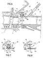
- FIGS 6 to 8 show a sealing device 50 of the brush seal type disposed between the radially inner portion 7a of the annular structure 7, substantially parallel to the leg 13, and the upstream portion 12a of the outer casing of the grille 10 of the diffuser.
- parts or elements identical to those of Figures 1 to 5 bear the same references.
- the figure 6 shows a first embodiment of the invention.
- the upstream portion 12a of the outer casing 12 has at its periphery an upstream flange 33a and a downstream flange 33b defining between them a groove 32, in which is fixed by means of rivets 34, the radially inner portion 51 or body of a joint with brushes, from which the bristles 52 extend outwards.
- the body 51 can be made either in the form of sectors or in the form of a split ring, and its width is a function of the width of the bristle. groove 32 so that after the establishment of the rivets 34, the seal is provided at the throat 32
- the spoiler 40 of the state of the art illustrated on the Figures 1 to 5 here is lying downstream. It is thus in the form of a sleeve 53 whose inner surface 54 is cylindrical.
- the flanges 33a and 33b and the brush seal 50 are disposed inside the sleeve 53.
- the length of the bristles is calculated in such a way that their free ends always bear against the surface 54.
- the flexibility and density of the bristles 52 ensure a perfect seal even regardless of the difference in air pressure between the two faces of the seal 50, and whatever the relative axial and radial displacement between the upstream portion 12a of the casing 12 and the sleeve 53.
- the figure 7 shows a second embodiment of the invention.
- the body 51 of the brush seal 50 is fixed in the peripheral groove 32 of a ring 60 of U section, this ring 60 has wings 33a and 33b defining the groove 32, and the body 51 is fixed by rivets 34.
- This ring 60 equipped with the seal 50 is then attached to the periphery of the upstream portion 12a of the outer casing 12 by welding.
- the ring 60 and the seal 50 can obviously be sectored.
- the figure 8 shows a third embodiment of the invention which differs from that of the figure 7 in that the brush seal 50, sectored or not, has in its radially inner region a metal ring 70 which can be fixed by welding to the periphery of the upstream portion 12a of the outer casing 12 of the diffuser grid.
Landscapes
- Engineering & Computer Science (AREA)
- Mechanical Engineering (AREA)
- General Engineering & Computer Science (AREA)
- Chemical & Material Sciences (AREA)
- Combustion & Propulsion (AREA)
- Structures Of Non-Positive Displacement Pumps (AREA)
- Gasket Seals (AREA)
Claims (4)
- Turbostrahltriebwerk, das von stromauf nach stromab, wobei stromauf und stromab durch die Zirkulationsrichtung des Primärstroms definiert sind, einen Hochdruckverdichter (1), ein Diffusorgitter (10) und eine Brennkammer umfasst, wobei der Hochdruckverdichter einen Außenring (6) umfasst, der den Kanal des Primärstroms radial begrenzt und an eine ringförmige Struktur (7) angeschlossen ist, die sich radial nach außen erstreckt, wobei das Diffusorgitter in der axialen Verlängerung des Verdichteraußenrings (6) ein Außengehäuse (12) umfasst, das mit einer konischen Stütze (13) verbunden ist, die nach hinten gerichtet ist und stromauf den Boden der Brennkammer begrenzt, wobei die Stütze ihrerseits mit einem Gehäuseaußenring (14) verbunden ist, der sich in stromaufwärtige Richtung erstreckt und durch Befestigungsmittel an der ringförmigen Struktur (7) befestigt ist, wobei die Stütze, der Gehäuseaußenring und die ringförmige Struktur einen Hohlraum (20) um das Diffusorgitter (10) herum definieren, wobei Öffnungen (22) zur Luftentnahme in der Stütze (13) ausgebildet sind, um den Kammerboden mit dem Hohlraum (20) in Verbindung zu bringen, wobei der Gehäuseaußenring mit Luftentnahmeöffnungen (23) ausgestattet ist und wobei Dichtungsmittel zwischen der ringförmigen Struktur (7) und dem Diffusorgitter-Außengehäuse (12) vorgesehen sind, um den Hohlraum (20) von dem Kanal des Primärstroms zu isolieren,
dadurch gekennzeichnet, dass die Dichtungsmittel durch eine Bürstendichtung (50), die am Umfang des stromaufwärtigen Teils (12a) des Außengehäuses (12) des Diffusorgitters befestigt ist, gebildet sind, wobei die Dichtung (50) Borsten (52) umfasst, die sich radial nach außen erstrecken und die an der Innenfläche (54) einer zylindrischen Manschette (53), welche mit der ringförmigen Struktur (7) fest verbunden ist und die Bürstendichtung (50) umgibt, in Anlage sind. - Turbostrahltriebwerk nach Anspruch 1, dadurch gekennzeichnet, dass der stromaufwärtige Teil (12a) des Außengehäuses (12) an seinem Umfang eine Nut (32) aufweist und die Bürstendichtung (50) in der Nut (32) durch Befestigungsmittel (34) befestigt ist.
- Turbostrahltriebwerk nach Anspruch 1, dadurch gekennzeichnet, dass die Bürstendichtung (50) durch Befestigungsmittel (34) in der Umfangsnut (32) eines Rings (60) mit U-förmigem Querschnitt befestigt ist und der Ring an dem Umfang des stromaufwärtigen Teils (12a) des Außengehäuses festgeschweißt ist.
- Turbostrahltriebwerk nach Anspruch 1, dadurch gekennzeichnet, dass die Bürstendichtung (50) in ihrem radial inneren Bereich einen Metallring (70) aufweist und der Ring (70) an dem Umfang des stromaufwärtigen Teils (12a) des Außengehäuses (12) festgeschweißt ist.
Applications Claiming Priority (2)
| Application Number | Priority Date | Filing Date | Title |
|---|---|---|---|
| FR0311021A FR2860040B1 (fr) | 2003-09-19 | 2003-09-19 | Realisation de l'etancheite dans un turboreacteur pour le prelevement cabine par un joint a brosse |
| FR0311021 | 2003-09-19 |
Publications (2)
| Publication Number | Publication Date |
|---|---|
| EP1517006A1 EP1517006A1 (de) | 2005-03-23 |
| EP1517006B1 true EP1517006B1 (de) | 2015-07-29 |
Family
ID=34178924
Family Applications (1)
| Application Number | Title | Priority Date | Filing Date |
|---|---|---|---|
| EP04292229.4A Expired - Lifetime EP1517006B1 (de) | 2003-09-19 | 2004-09-17 | Gasturbine mit Bürstendichtung |
Country Status (6)
| Country | Link |
|---|---|
| US (1) | US20050102994A1 (de) |
| EP (1) | EP1517006B1 (de) |
| KR (1) | KR20050028785A (de) |
| CN (1) | CN100419236C (de) |
| FR (1) | FR2860040B1 (de) |
| RU (1) | RU2355894C2 (de) |
Families Citing this family (15)
| Publication number | Priority date | Publication date | Assignee | Title |
|---|---|---|---|---|
| FR2860039B1 (fr) * | 2003-09-19 | 2005-11-25 | Snecma Moteurs | Realisation de l'etancheite dans un turboreacteur pour le prelevement cabine par joints double sens a lamelles |
| FR2875851B1 (fr) * | 2004-09-28 | 2006-12-29 | Snecma Moteurs Sa | Dispositif d'etancheite dispose entre un compresseur haute-pression et un diffuseur de turbomachine |
| EP1965029A1 (de) * | 2007-03-02 | 2008-09-03 | Siemens Aktiengesellschaft | Statische Abdichtung Einlaufgehäuse zu Diffusor mittels Bürstendichtung für Heissgasexpander |
| US20080296846A1 (en) * | 2007-05-29 | 2008-12-04 | Eaton Corporation | Static outside diameter brush seal assembly |
| FR2918144B1 (fr) | 2007-06-29 | 2009-11-06 | Snecma Sa | Joint a brosse dynamique. |
| FR2957976B1 (fr) * | 2010-03-26 | 2013-04-12 | Snecma | Dispositif d'etancheite pour une enceinte d'huile d'un turboreacteur |
| CN102581486B (zh) * | 2012-02-06 | 2014-08-20 | 江苏透平密封高科技有限公司 | 刷式密封激光渗透打点焊接方法 |
| US20140144158A1 (en) * | 2012-11-29 | 2014-05-29 | General Electric Company | Turbomachine component including a seal member |
| US9752607B2 (en) * | 2013-03-13 | 2017-09-05 | Rolls-Royce North American Technologies, Inc. | Retention pin and method of forming |
| CN105716114B (zh) * | 2014-12-04 | 2018-05-08 | 中国航空工业集团公司沈阳发动机设计研究所 | 一种可拆换的矩形扩压器 |
| GB2537825A (en) * | 2015-04-22 | 2016-11-02 | Francis Mitchell Martin | Universal seal |
| US11428241B2 (en) * | 2016-04-22 | 2022-08-30 | Raytheon Technologies Corporation | System for an improved stator assembly |
| CN106226056A (zh) * | 2016-08-12 | 2016-12-14 | 中国航空工业集团公司沈阳发动机设计研究所 | 一种扩压器 |
| US11174786B2 (en) | 2016-11-15 | 2021-11-16 | General Electric Company | Monolithic superstructure for load path optimization |
| FR3061740B1 (fr) * | 2017-01-11 | 2019-08-09 | Safran Aircraft Engines | Redresseur a tenue vibratoire renforcee |
Family Cites Families (11)
| Publication number | Priority date | Publication date | Assignee | Title |
|---|---|---|---|---|
| US3777489A (en) * | 1972-06-01 | 1973-12-11 | Gen Electric | Combustor casing and concentric air bleed structure |
| CA1221034A (en) * | 1985-06-28 | 1987-04-28 | Pratt & Whitney Canada Inc. | Impeller shroud |
| FR2616889B1 (fr) * | 1987-06-18 | 1992-07-31 | Snecma | Carter de chambre de combustion de turboreacteur comportant des orifices de prelevement d'air |
| US5181728A (en) * | 1991-09-23 | 1993-01-26 | General Electric Company | Trenched brush seal |
| US5265412A (en) * | 1992-07-28 | 1993-11-30 | General Electric Company | Self-accommodating brush seal for gas turbine combustor |
| US5400586A (en) * | 1992-07-28 | 1995-03-28 | General Electric Co. | Self-accommodating brush seal for gas turbine combustor |
| FR2694962B1 (fr) * | 1992-08-19 | 1994-10-21 | Snecma | Turboréacteur dont la chambre de combustion est protégée contre les effets d'une ingestion massive d'eau. |
| US6131911A (en) * | 1992-11-19 | 2000-10-17 | General Electric Co. | Brush seals and combined labyrinth and brush seals for rotary machines |
| RU2171403C1 (ru) * | 1999-12-21 | 2001-07-27 | Открытое акционерное общество "Авиадвигатель" | Компрессор газотурбинного двигателя |
| US6540231B1 (en) * | 2000-02-29 | 2003-04-01 | General Electric Company | Surface following brush seal |
| US6382632B1 (en) * | 2001-02-21 | 2002-05-07 | General Electric Company | Repositionable brush seal for turbomachinery |
-
2003
- 2003-09-19 FR FR0311021A patent/FR2860040B1/fr not_active Expired - Fee Related
-
2004
- 2004-09-08 KR KR1020040071515A patent/KR20050028785A/ko not_active Ceased
- 2004-09-13 US US10/938,571 patent/US20050102994A1/en not_active Abandoned
- 2004-09-15 CN CNB2004100791998A patent/CN100419236C/zh not_active Expired - Fee Related
- 2004-09-17 RU RU2004127896/06A patent/RU2355894C2/ru not_active IP Right Cessation
- 2004-09-17 EP EP04292229.4A patent/EP1517006B1/de not_active Expired - Lifetime
Also Published As
| Publication number | Publication date |
|---|---|
| US20050102994A1 (en) | 2005-05-19 |
| RU2004127896A (ru) | 2006-02-20 |
| EP1517006A1 (de) | 2005-03-23 |
| RU2355894C2 (ru) | 2009-05-20 |
| FR2860040B1 (fr) | 2006-02-10 |
| KR20050028785A (ko) | 2005-03-23 |
| FR2860040A1 (fr) | 2005-03-25 |
| CN1598272A (zh) | 2005-03-23 |
| CN100419236C (zh) | 2008-09-17 |
Similar Documents
| Publication | Publication Date | Title |
|---|---|---|
| EP1517005B1 (de) | Gasturbine mit einem Abdichtdelement mit Lamellenstruktur | |
| EP1517006B1 (de) | Gasturbine mit Bürstendichtung | |
| EP2009333B1 (de) | Dynamische Bürstendichtung | |
| EP2060750B1 (de) | Turbinen- oder Kompressorstufe, insbesondere eines Turbotriebwerks | |
| CA2739208C (fr) | Etancheite entre une chambre de combustion et un distributeur de turbine dans une turbomachine | |
| EP1515004B1 (de) | Dichtung vom Kolbenringtyp für den Verdichter einer Gasturbine | |
| EP4240956B1 (de) | Anordnung für eine turbomaschine | |
| EP2582920B1 (de) | Leitschaufelsegment für einen verdichter einer turbomaschine | |
| FR3018548A1 (fr) | Turboreacteur a conduit de decharge | |
| EP1519009B1 (de) | Turbomaschine mit Luftentnahme für die Kabine über ein Kugelgelenkrohr | |
| FR2971022A1 (fr) | Etage redresseur de compresseur pour une turbomachine | |
| FR2919345A1 (fr) | Anneau pour une roue de turbine de turbomachine. | |
| FR2923528A1 (fr) | Etage de turbine ou de compresseur d'un turboreacteur | |
| FR2896548A1 (fr) | Ensemble de redresseurs fixes sectorise pour un compresseur de turbomachine | |
| EP4544155B1 (de) | Beschaufelte anordnung für turbomaschine, turbine für turbomaschine und turbomaschine | |
| WO2020115383A1 (fr) | Dispositif ameliore d'etancheite a l'air destine a etre interpose entre un element de carter de turbomachine d'aeronef a double flux, et un element de nacelle | |
| EP4121637A1 (de) | Turbomaschinenrotoranordnung mit einem ringförmigen klemmteil | |
| FR3116305A1 (fr) | Arbre de liaison d’un corps haute pression d’une turbomachine | |
| FR3120895A1 (fr) | Dispositif de joint d’etancheite a labyrinthe | |
| FR3107725A1 (fr) | Ensemble pour stator de turbomachine d’aéronef, à étanchéité renforcée entre une virole externe et une couronne aubagée de stator entourée par cette virole | |
| EP4409113B1 (de) | Hochdruck-gasturbine für eine turbomaschine und turbomaschine | |
| FR3115819A1 (fr) | Ensemble de stator de turbomachine d’aéronef, comprenant une structure externe formée de deux tronçons annulaires entourant une couronne aubagée de stator | |
| WO2020207909A1 (fr) | Dispositif ameliore d'attache d'aubes dans une turbine contrarotative |
Legal Events
| Date | Code | Title | Description |
|---|---|---|---|
| PUAI | Public reference made under article 153(3) epc to a published international application that has entered the european phase |
Free format text: ORIGINAL CODE: 0009012 |
|
| 17P | Request for examination filed |
Effective date: 20040924 |
|
| AK | Designated contracting states |
Kind code of ref document: A1 Designated state(s): AT BE BG CH CY CZ DE DK EE ES FI FR GB GR HU IE IT LI LU MC NL PL PT RO SE SI SK TR |
|
| AX | Request for extension of the european patent |
Extension state: AL HR LT LV MK |
|
| RAP1 | Party data changed (applicant data changed or rights of an application transferred) |
Owner name: SNECMA |
|
| AKX | Designation fees paid |
Designated state(s): DE FR GB SE |
|
| GRAP | Despatch of communication of intention to grant a patent |
Free format text: ORIGINAL CODE: EPIDOSNIGR1 |
|
| INTG | Intention to grant announced |
Effective date: 20150212 |
|
| GRAS | Grant fee paid |
Free format text: ORIGINAL CODE: EPIDOSNIGR3 |
|
| GRAA | (expected) grant |
Free format text: ORIGINAL CODE: 0009210 |
|
| AK | Designated contracting states |
Kind code of ref document: B1 Designated state(s): DE FR GB SE |
|
| REG | Reference to a national code |
Ref country code: GB Ref legal event code: FG4D Free format text: NOT ENGLISH |
|
| REG | Reference to a national code |
Ref country code: DE Ref legal event code: R096 Ref document number: 602004047563 Country of ref document: DE |
|
| REG | Reference to a national code |
Ref country code: FR Ref legal event code: PLFP Year of fee payment: 12 |
|
| REG | Reference to a national code |
Ref country code: SE Ref legal event code: TRGR |
|
| REG | Reference to a national code |
Ref country code: DE Ref legal event code: R097 Ref document number: 602004047563 Country of ref document: DE |
|
| PLBE | No opposition filed within time limit |
Free format text: ORIGINAL CODE: 0009261 |
|
| STAA | Information on the status of an ep patent application or granted ep patent |
Free format text: STATUS: NO OPPOSITION FILED WITHIN TIME LIMIT |
|
| 26N | No opposition filed |
Effective date: 20160502 |
|
| REG | Reference to a national code |
Ref country code: FR Ref legal event code: PLFP Year of fee payment: 13 |
|
| REG | Reference to a national code |
Ref country code: FR Ref legal event code: PLFP Year of fee payment: 14 |
|
| PGFP | Annual fee paid to national office [announced via postgrant information from national office to epo] |
Ref country code: GB Payment date: 20170821 Year of fee payment: 14 Ref country code: DE Payment date: 20170821 Year of fee payment: 14 |
|
| PGFP | Annual fee paid to national office [announced via postgrant information from national office to epo] |
Ref country code: SE Payment date: 20170824 Year of fee payment: 14 |
|
| REG | Reference to a national code |
Ref country code: FR Ref legal event code: CD Owner name: SAFRAN AIRCRAFT ENGINES, FR Effective date: 20170717 |
|
| REG | Reference to a national code |
Ref country code: FR Ref legal event code: PLFP Year of fee payment: 15 |
|
| REG | Reference to a national code |
Ref country code: DE Ref legal event code: R119 Ref document number: 602004047563 Country of ref document: DE |
|
| REG | Reference to a national code |
Ref country code: SE Ref legal event code: EUG |
|
| GBPC | Gb: european patent ceased through non-payment of renewal fee |
Effective date: 20180917 |
|
| PG25 | Lapsed in a contracting state [announced via postgrant information from national office to epo] |
Ref country code: SE Free format text: LAPSE BECAUSE OF NON-PAYMENT OF DUE FEES Effective date: 20180918 |
|
| PG25 | Lapsed in a contracting state [announced via postgrant information from national office to epo] |
Ref country code: DE Free format text: LAPSE BECAUSE OF NON-PAYMENT OF DUE FEES Effective date: 20190402 |
|
| PG25 | Lapsed in a contracting state [announced via postgrant information from national office to epo] |
Ref country code: GB Free format text: LAPSE BECAUSE OF NON-PAYMENT OF DUE FEES Effective date: 20180917 |
|
| PGFP | Annual fee paid to national office [announced via postgrant information from national office to epo] |
Ref country code: FR Payment date: 20230822 Year of fee payment: 20 |