EP2009333B1 - Dynamische Bürstendichtung - Google Patents
Dynamische Bürstendichtung Download PDFInfo
- Publication number
- EP2009333B1 EP2009333B1 EP08158906.1A EP08158906A EP2009333B1 EP 2009333 B1 EP2009333 B1 EP 2009333B1 EP 08158906 A EP08158906 A EP 08158906A EP 2009333 B1 EP2009333 B1 EP 2009333B1
- Authority
- EP
- European Patent Office
- Prior art keywords
- seal
- container
- insulators
- textile
- rotor
- Prior art date
- Legal status (The legal status is an assumption and is not a legal conclusion. Google has not performed a legal analysis and makes no representation as to the accuracy of the status listed.)
- Active
Links
Images
Classifications
-
- F—MECHANICAL ENGINEERING; LIGHTING; HEATING; WEAPONS; BLASTING
- F01—MACHINES OR ENGINES IN GENERAL; ENGINE PLANTS IN GENERAL; STEAM ENGINES
- F01D—NON-POSITIVE DISPLACEMENT MACHINES OR ENGINES, e.g. STEAM TURBINES
- F01D11/00—Preventing or minimising internal leakage of working-fluid, e.g. between stages
- F01D11/001—Preventing or minimising internal leakage of working-fluid, e.g. between stages for sealing space between stator blade and rotor
-
- F—MECHANICAL ENGINEERING; LIGHTING; HEATING; WEAPONS; BLASTING
- F16—ENGINEERING ELEMENTS AND UNITS; GENERAL MEASURES FOR PRODUCING AND MAINTAINING EFFECTIVE FUNCTIONING OF MACHINES OR INSTALLATIONS; THERMAL INSULATION IN GENERAL
- F16J—PISTONS; CYLINDERS; SEALINGS
- F16J15/00—Sealings
- F16J15/16—Sealings between relatively-moving surfaces
- F16J15/32—Sealings between relatively-moving surfaces with elastic sealings, e.g. O-rings
- F16J15/3284—Sealings between relatively-moving surfaces with elastic sealings, e.g. O-rings characterised by their structure; Selection of materials
- F16J15/3288—Filamentary structures, e.g. brush seals
-
- F—MECHANICAL ENGINEERING; LIGHTING; HEATING; WEAPONS; BLASTING
- F05—INDEXING SCHEMES RELATING TO ENGINES OR PUMPS IN VARIOUS SUBCLASSES OF CLASSES F01-F04
- F05D—INDEXING SCHEME FOR ASPECTS RELATING TO NON-POSITIVE-DISPLACEMENT MACHINES OR ENGINES, GAS-TURBINES OR JET-PROPULSION PLANTS
- F05D2240/00—Components
- F05D2240/55—Seals
- F05D2240/56—Brush seals
Definitions
- the invention relates to a dynamic brush seal assembly for sealing between a rotor and a stator, and a turbine or a compressor comprising such a seal and a turbine engine comprising such a turbine or such a compressor.
- Brush seals of this type are used in particular for sealing between an enclosure containing air and an enclosure containing a mixture of air and oil or a seal between two enclosures containing air at the compressors. high and low pressure and at high and low pressure turbines.
- the invention relates to a brush seal consisting of non-metallic bristles, able to seal a gap between a rotor and a stator comprising a housing for the bristles fixed on the rotor or on the stator, the bristles being subjected on one side, at an upstream pressure and on another face at a downstream pressure, the upstream pressure being greater than the downstream pressure.
- the seals currently used in these applications are labyrinth type seals which comprise annular teeth called wipers materializing vis-à-vis a ring of softer material called abradable a plurality of section restrictions generating a pressure drop and therefore a flow reduction.
- the air permeability is important, as a result, the turbomachine consumes oil which incurs costs and is also toxic to the environment.
- Wire brush seals which have been the subject of turbine engine applications since the 1950s are still known.
- the most important point to note about this technology is the need to bend the bristles on a barrier resistant to the pressure (the back ring).
- the consequence is a stiffening of the brushes proportional to the applied pressure which can cause accelerated wear of the brushes if the game is canceled in these conditions.
- the slightest contact with the rotor causes rapid wear of the seal and degradation of the sealing characteristics.
- the document GB 2,291,939 discloses a brush seal comprising non-metallic bristles, adapted to seal a gap between a rotor and a stator comprising a housing for the bristles fixed on the stator, the bristles being subjected, on one side, to an upstream pressure and on another side at a downstream pressure, the bristles being supported on the rotor so as to be inclined on the side of the seal where the weakest pressure prevails, in accordance with the preamble of claim 1.
- the present invention relates to a dynamic brush seal that overcomes the disadvantages of the prior art.
- the housing comprises an inner envelope on which the bristles are wound and an outer envelope which surrounds the bristles.
- the brush seal comprises an upstream ring and a downstream ring disposed between the outer casing and the bristles.
- the inner envelope and the outer envelope have a C shape.
- the brush seal comprises a coil spring disposed in the center of the inner casing, any type of elastic ring can also provide this function.
- the downstream ring comprises a chamfer.
- the brush seal is mounted on a support, said support having a housing in which the housing is received and a snap ring to immobilize the housing in the housing.
- downstream ring is shorter than the support and the support has a radius on which the bristles come to bear to take a curved shape.
- the snap ring crushes the housing so as to ensure, by the deformation of the housing, a static seal between the housing and the housing housing.
- the invention relates to a turbomachine turbine or compressor comprising a brush seal according to the invention.
- the invention relates to a turbine engine comprising a turbine and / or a compressor equipped with a brush seal according to the invention.
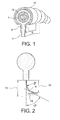
- the brush seal has an upwardly open C-shaped inner casing 2.
- the bristles 4 forming the brush are wound on this inner envelope.
- the bristles are held by an upstream ring 6 and a downstream ring 8.
- the upstream ring 6 and the downstream ring 8 are held in place by an outer casing 10 having the form C open downwards.
- a helical spring 12 is present inside the inner casing 2. The latter rests on the helical spring 12.
- the angle ⁇ is between 5 ° and 45 ° and preferably between 10 ° and 30 ° °.
- the brush consists of carbon bristles with a diameter of about 6 microns.
- the thickness of the sheet varies between one millimeter and 4 millimeters depending on the application.
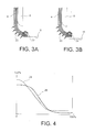
- the reference 14 designates the free length of the bristles 4 while the reference 16 represents the height under the rear ring of the curved bristles 4 bearing on the rotor 18.
- the angle of the bristles with respect to a perpendicular to the surface of the rotor 18 is designated by ⁇ .
- the radius of curvature of the bristles has their curved end designated by the letter p.
- the inner casing 2, the outer casing 10, the upstream and downstream rings 6, 8 constitute a casing.
- On the figure 3A the bristles 4 rest on the rotor 18.
- the bristles are subjected to upstream pressure and downstream pressure whose difference constitutes a differential pressure 20.
- the bristles 4 exert a contact pressure 22 on the rotor 18.
- This contact pressure 22 is decreased by the differential pressure 20 which tends to lift the bristles of the rotor 18.
- the invention does not try to fight against the pressure by buttressing the bristles against the rear ring.
- the rear ring play is even dimensioned so that the sheet can migrate between the rotor and the latter.
- the bristles can lift their support on the rotor 18. There is then a slight clearance between the end of the bristle and the rotor 18 and a leakage rate occurs in this game.
- the present invention allows to manage this flow of leak.
- the brushes are deflected under the rear ring 8.
- the aerodynamic forces are exerted freely in operation on the sheet and can raise it from the rotor for high differential pressures.
- the permeability characteristic is strongly degraded above 2.5 bar but wear is obtained which becomes degressive with the pressurization.
- seals are effective only at low pressure.
- the most harmful operation for the service life of the rotor / stator contact is idling.
- the low slip speed under these conditions guarantees a reduced wear rate for many applications.
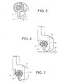
- the figure 5 represents an alternative embodiment in which the swallow ring 8 comprises a chamfer 30.
- This function of the chamfer is to facilitate the inclination of the brushes and reduce the risk of shearing bristles.
- the hairs are not of the same length. This stems in particular from the fact that the ends of the hairs have been shown in a pointed manner on the figure 5 .
- the figure 6 illustrates how the seal housing is mounted on a support 32.
- the support has a housing 34 in which is received the case.
- a snap ring 36 immobilizes the housing in the housing 34.
- the snap ring 36 is arranged in such a way as to slightly crush the casing in order to ovalise it and to apply its part. upper 38 against the surface of the housing 34 so as to achieve a static seal between the housing and the housing.
- the housing 32 has a rounded portion 38 on which the bristles 4 come to bear.
- the function of the rounding 38 is therefore similar to that of the chamfer 30 of the embodiment shown in FIG. figure 5 . It aims to facilitate the inclination of the free end of the bristles.
Landscapes
- Engineering & Computer Science (AREA)
- General Engineering & Computer Science (AREA)
- Mechanical Engineering (AREA)
- Turbine Rotor Nozzle Sealing (AREA)
- Sealing Devices (AREA)
- Structures Of Non-Positive Displacement Pumps (AREA)
Claims (10)
- Bürstendichtung mit nicht metallischen Fasern und einem Gehäuse für die Fasern (4), wobei die Dichtung in der Lage ist, eine Dichtheit eines Luftspaltes zwischen einem Rotor (18) und einem Stator sicherzustellen,
wobei das Gehäuse an dem Rotor oder an dem Stator befestigt werden kann, wobei die Fasern derart ausgeführt sind, dass sie auf einer Seite einem stromaufwärtigen Druck und auf einer anderen Seite einem stromabwärtigen Druck ausgesetzt sind, wobei der stromaufwärtige Druck höher als der stromabwärtige Druck ist, wobei die Fasern (4) so ausgeführt sind, dass sie derart auf dem Stator oder dem Rotor (18) aufliegen, dass sie auf der Seite der Dichtung geneigt sind, wo der geringste Druck vorherrscht, nämlich der stromabwärtige Druck,
wobei das Gehäuse eine innere Umhüllung (2), an der die Fasern aufgerollt sind, und eine äußere Umhüllung (10) aufweist, die die Fasern umgibt,
dadurch gekennzeichnet, dass das Gehäuse außerdem einen stromaufwärtigen Ring (6) und einen stromabwärtigen Ring (8) aufweist, wobei der stromaufwärtige Ring (6) und der stromabwärtige Ring (8) zwischen der äußeren Umhüllung (10) und den Fasern (4) angeordnet sind. - Bürstendichtung gemäß Anspruch 1, dadurch gekennzeichnet, dass die Fasern (4) in der Strömungsrichtung in einem Winkel α zwischen 5° und 45° und bevorzugt zwischen 10° und 30° geneigt sind.
- Bürstendichtung gemäß Anspruch 1 oder 2, dadurch gekennzeichnet, dass die innere Umhüllung (2) und die äußere Umhüllung (10) eine C-Form aufweisen.
- Bürstendichtung gemäß Anspruch 3, dadurch gekennzeichnet, dass diese eine Schraubenfeder (12) aufweist, die in der Mitte der inneren Umhüllung (2) angebracht ist.
- Bürstendichtung gemäß einem der vorhergehenden Ansprüche, dadurch gekennzeichnet, dass der stromabwärtige Ring (8) eine Fase (30) aufweist.
- Anordnung bestehend aus einer Halterung (32) und einer Bürstendichtung gemäß einem der Ansprüche 1 bis 5, dadurch gekennzeichnet, dass die Dichtung an der Halterung (32) angebracht ist, wobei die Halterung eine Aufnahme (34) aufweist, in der das Gehäuse und ein Sicherungsring (36) zur Festsetzung des Gehäuses in der Aufnahme (34) aufgenommen sind.
- Anordnung gemäß Anspruch 6, dadurch gekennzeichnet, dass der stromabwärtige Ring (8) kürzer als die Halterung (32) ist und dass die Halterung einen Bereich (38) aufweist, auf dem die Fasern (4) zur Auflage kommen, um eine gekrümmte Form anzunehmen.
- Anordnung gemäß Anspruch 7, dadurch gekennzeichnet, dass der Sicherungsring (36) das Gehäuse derart zusammendrückt, dass durch die Verformung des Gehäuses eine statische Dichtheit zwischen dem Gehäuse und der Aufnahme (34) des Gehäuses gewährleistet wird.
- Turbine oder Kompressor einer Turbomaschine, dadurch gekennzeichnet, dass diese/r eine Bürstendichtung und/oder eine Anordnung gemäß einem der Ansprüche 1 bis 8 umfasst.
- Turbomaschine, dadurch gekennzeichnet, dass diese eine Turbine und/oder einen Kompressor gemäß Anspruch 9 umfasst.
Applications Claiming Priority (1)
| Application Number | Priority Date | Filing Date | Title |
|---|---|---|---|
| FR0756153A FR2918144B1 (fr) | 2007-06-29 | 2007-06-29 | Joint a brosse dynamique. |
Publications (2)
| Publication Number | Publication Date |
|---|---|
| EP2009333A1 EP2009333A1 (de) | 2008-12-31 |
| EP2009333B1 true EP2009333B1 (de) | 2015-12-23 |
Family
ID=38951923
Family Applications (1)
| Application Number | Title | Priority Date | Filing Date |
|---|---|---|---|
| EP08158906.1A Active EP2009333B1 (de) | 2007-06-29 | 2008-06-24 | Dynamische Bürstendichtung |
Country Status (7)
| Country | Link |
|---|---|
| US (1) | US8011666B2 (de) |
| EP (1) | EP2009333B1 (de) |
| JP (1) | JP5367311B2 (de) |
| CA (1) | CA2635768C (de) |
| FR (1) | FR2918144B1 (de) |
| RU (1) | RU2454558C2 (de) |
| UA (1) | UA96588C2 (de) |
Families Citing this family (18)
| Publication number | Priority date | Publication date | Assignee | Title |
|---|---|---|---|---|
| FR2957976B1 (fr) * | 2010-03-26 | 2013-04-12 | Snecma | Dispositif d'etancheite pour une enceinte d'huile d'un turboreacteur |
| US9121297B2 (en) * | 2011-03-28 | 2015-09-01 | General Electric Company | Rotating brush seal |
| US9528384B2 (en) * | 2011-06-27 | 2016-12-27 | General Electric Company | Brush seal |
| US8657298B2 (en) * | 2011-08-15 | 2014-02-25 | General Electric Company | Brush seal with backing plate tooth |
| FR2995379B1 (fr) * | 2012-09-10 | 2014-09-05 | Commissariat Energie Atomique | Joint circulaire d'etancheite a brosse |
| FR2998611B1 (fr) * | 2012-11-29 | 2018-08-10 | Safran Aircraft Engines | Ensemble formant joint d'etancheite pour une turbomachine comportant un joint a brosse |
| FR2998922B1 (fr) | 2012-12-05 | 2018-06-15 | Safran Aircraft Engines | Etancheite d'enceintes de turbomachine realisee par joint a brosse et labyrinthe |
| FR3001197A1 (fr) * | 2013-01-22 | 2014-07-25 | Airbus Operations Sas | Ensemble propulsif d'un aeronef comprenant au moins un joint a brosse resistant aux hautes temperatures |
| FR3010462B1 (fr) | 2013-09-11 | 2021-10-08 | Snecma | Secteur angulaire de redresseur pour compresseur de turbomachine comportant un joint d'etancheite a brosse |
| KR101484879B1 (ko) * | 2014-01-08 | 2015-01-20 | 두산중공업 주식회사 | 터보머신의 실링장치 |
| DE102014200525A1 (de) * | 2014-01-14 | 2015-07-16 | Intellectual Property Management MTU Aero Engines AG | Bürstendichtung mit Bürstenfasern aus nichtmetallischen Werkstoffen |
| FR3018109B1 (fr) * | 2014-02-28 | 2016-05-06 | Snecma | Reduction du debit de fuite d'un joint a brosse par obstruction geometrique flexible |
| KR101620166B1 (ko) * | 2014-06-17 | 2016-05-23 | 두산중공업 주식회사 | 브러시 실 어셈블리 |
| CN105298553B (zh) * | 2014-06-17 | 2018-03-06 | 斗山重工业株式会社 | 刷式密封组件 |
| KR101616619B1 (ko) * | 2014-06-17 | 2016-04-28 | 두산중공업 주식회사 | 브러시 실 어셈블리 |
| CN105317470B (zh) | 2014-06-17 | 2017-06-16 | 斗山重工业株式会社 | 刷式密封组件 |
| RU2719753C1 (ru) * | 2019-11-25 | 2020-04-23 | Акционерное общество "ОДК-Климов" | Щёточное уплотнение |
| US12253178B2 (en) * | 2021-12-17 | 2025-03-18 | Process Combustion Corporation | Indexing valve for regenerative thermal oxidizer |
Family Cites Families (16)
| Publication number | Priority date | Publication date | Assignee | Title |
|---|---|---|---|---|
| US4202554A (en) * | 1978-05-17 | 1980-05-13 | Rolls-Royce Limited | Brush seals |
| DE3907614C2 (de) * | 1988-01-29 | 2000-08-03 | Mtu Muenchen Gmbh | Bürstendichtung |
| GB2250790B (en) * | 1990-12-12 | 1994-04-27 | Rolls Royce Plc | Brush seal |
| FR2692019B1 (fr) * | 1992-06-05 | 1994-07-22 | Commissariat Energie Atomique | Joint flexible a jaquette. |
| US5400586A (en) | 1992-07-28 | 1995-03-28 | General Electric Co. | Self-accommodating brush seal for gas turbine combustor |
| US5401036A (en) * | 1993-03-22 | 1995-03-28 | Eg & G Sealol, Inc. | Brush seal device having a recessed back plate |
| RU2076256C1 (ru) * | 1994-06-15 | 1997-03-27 | Научно-исследовательский институт технологии и организации производства двигателей | Способ изготовления щеточных уплотнений гтд |
| DE4427265C1 (de) * | 1994-07-30 | 1996-04-04 | Mtu Muenchen Gmbh | Bürstendichtung für Turbomaschinen zur Abdichtung unterschiedlich druckbeaufschlagter Räume zwischen einem Maschinenstator und einem Maschinenrotor |
| IT1284468B1 (it) * | 1995-07-28 | 1998-05-21 | Mtu Muenchen Gmbh | Guarnizione a spazzola per turbomacchine |
| DE29600193U1 (de) * | 1996-01-08 | 1996-03-14 | MTU Motoren- und Turbinen-Union München GmbH, 80995 München | Bürstendichtung mit C-förmigem Klemmring |
| DE19712088C2 (de) * | 1997-03-22 | 1999-06-24 | Mtu Muenchen Gmbh | Bürstendichtung mit in Umfangsrichtung schräg gestellten Borsten |
| JP2001182646A (ja) * | 1999-12-24 | 2001-07-06 | Toshiba Corp | ブラシシール装置 |
| DE10018273B4 (de) * | 2000-04-13 | 2005-10-20 | Mtu Aero Engines Gmbh | Bürstendichtung |
| FR2860040B1 (fr) | 2003-09-19 | 2006-02-10 | Snecma Moteurs | Realisation de l'etancheite dans un turboreacteur pour le prelevement cabine par un joint a brosse |
| GB2410533B (en) * | 2004-01-28 | 2006-02-08 | Rolls Royce Plc | Sealing arrangement |
| US20070187900A1 (en) * | 2004-05-04 | 2007-08-16 | Advanced Components & Materials, Inc. | Non-metallic brush seals |
-
2007
- 2007-06-29 FR FR0756153A patent/FR2918144B1/fr active Active
-
2008
- 2008-06-24 EP EP08158906.1A patent/EP2009333B1/de active Active
- 2008-06-27 UA UAA200808590A patent/UA96588C2/ru unknown
- 2008-06-27 JP JP2008168250A patent/JP5367311B2/ja active Active
- 2008-06-27 RU RU2008126324/06A patent/RU2454558C2/ru active
- 2008-06-27 US US12/163,034 patent/US8011666B2/en active Active
- 2008-06-27 CA CA2635768A patent/CA2635768C/fr active Active
Also Published As
| Publication number | Publication date |
|---|---|
| UA96588C2 (ru) | 2011-11-25 |
| FR2918144B1 (fr) | 2009-11-06 |
| US20090001668A1 (en) | 2009-01-01 |
| CA2635768A1 (fr) | 2008-12-29 |
| RU2008126324A (ru) | 2010-01-10 |
| FR2918144A1 (fr) | 2009-01-02 |
| JP5367311B2 (ja) | 2013-12-11 |
| EP2009333A1 (de) | 2008-12-31 |
| RU2454558C2 (ru) | 2012-06-27 |
| CA2635768C (fr) | 2015-06-02 |
| JP2009024872A (ja) | 2009-02-05 |
| US8011666B2 (en) | 2011-09-06 |
Similar Documents
| Publication | Publication Date | Title |
|---|---|---|
| EP2009333B1 (de) | Dynamische Bürstendichtung | |
| EP1564455A1 (de) | Dichtungsanordnung für die Hochdruckturbine einer Turbomaschine | |
| FR2955898A1 (fr) | Etancheite amont d'un anneau en cmc dans une turbine de turbomachine | |
| CA2885650C (fr) | Carter et roue a aubes de turbomachine | |
| EP2870323A1 (de) | Dichtungsvorrichtung für das lager einer turbomaschine mit zwei elastischen dichtungen | |
| FR2961554A1 (fr) | Secteur angulaire de redresseur pour compresseur de turbomachine, redresseur de turbomachine et turbomachine comprenant un tel secteur | |
| FR2997997A1 (fr) | Support de tube d'evacuation d'air dans une turbomachine | |
| EP4240956A1 (de) | Anordnung für eine turbomaschine | |
| FR2860040A1 (fr) | Realisation de l'etancheite dans un turboreacteur pour le prelevement cabine par un joint a brosse | |
| EP1515004B1 (de) | Dichtung vom Kolbenringtyp für den Verdichter einer Gasturbine | |
| FR3015591A1 (fr) | Virole de compresseur comprenant une lechette d'etancheite equipee d'une structure d'entrainement et de deviation d'air de fuite | |
| FR3075869A1 (fr) | Roue mobile de turbine pour turbomachine d'aeronef, comprenant un anneau d'etancheite retenu radialement par des excroissances sur l'echasse des aubes | |
| FR2896548A1 (fr) | Ensemble de redresseurs fixes sectorise pour un compresseur de turbomachine | |
| FR3005991A1 (fr) | Dispositif d'interface entre deux elements de turbomachine | |
| EP1818507B1 (de) | Laufrad eines Turbotriebwerks | |
| FR2888876A1 (fr) | Dispositif d'amortissement des vibrations d'un rotor dans une turbomachine | |
| BE1025092B1 (fr) | Joint a brosse pour rotor de turbomachine | |
| FR3023260A1 (fr) | Ensemble propulsif d'aeronef | |
| FR2877994A1 (fr) | Support de palier, et moteur d'aeronef equipe d'un tel support de palier. | |
| FR3094031A1 (fr) | Ensemble pour une turbomachine | |
| FR3116305A1 (fr) | Arbre de liaison d’un corps haute pression d’une turbomachine | |
| EP3931427B1 (de) | Anordnung für eine turbine einer turbomaschine | |
| FR3058758A1 (fr) | Turbomachine, telle par exemple qu'un turboreacteur ou un turbopropulseur d'avion | |
| FR3053083B1 (fr) | Anneau de carenage de roue a aubes | |
| FR3026795B1 (fr) | Carter de compresseur comportant des moyens d'etancheite ameliores |
Legal Events
| Date | Code | Title | Description |
|---|---|---|---|
| PUAI | Public reference made under article 153(3) epc to a published international application that has entered the european phase |
Free format text: ORIGINAL CODE: 0009012 |
|
| AK | Designated contracting states |
Kind code of ref document: A1 Designated state(s): AT BE BG CH CY CZ DE DK EE ES FI FR GB GR HR HU IE IS IT LI LT LU LV MC MT NL NO PL PT RO SE SI SK TR |
|
| AX | Request for extension of the european patent |
Extension state: AL BA MK RS |
|
| 17P | Request for examination filed |
Effective date: 20090603 |
|
| AKX | Designation fees paid |
Designated state(s): DE FR GB |
|
| 17Q | First examination report despatched |
Effective date: 20120822 |
|
| GRAP | Despatch of communication of intention to grant a patent |
Free format text: ORIGINAL CODE: EPIDOSNIGR1 |
|
| INTG | Intention to grant announced |
Effective date: 20150703 |
|
| GRAS | Grant fee paid |
Free format text: ORIGINAL CODE: EPIDOSNIGR3 |
|
| GRAA | (expected) grant |
Free format text: ORIGINAL CODE: 0009210 |
|
| AK | Designated contracting states |
Kind code of ref document: B1 Designated state(s): DE FR GB |
|
| REG | Reference to a national code |
Ref country code: GB Ref legal event code: FG4D Free format text: NOT ENGLISH |
|
| REG | Reference to a national code |
Ref country code: DE Ref legal event code: R096 Ref document number: 602008041640 Country of ref document: DE |
|
| REG | Reference to a national code |
Ref country code: FR Ref legal event code: PLFP Year of fee payment: 9 |
|
| REG | Reference to a national code |
Ref country code: DE Ref legal event code: R097 Ref document number: 602008041640 Country of ref document: DE |
|
| PLBE | No opposition filed within time limit |
Free format text: ORIGINAL CODE: 0009261 |
|
| STAA | Information on the status of an ep patent application or granted ep patent |
Free format text: STATUS: NO OPPOSITION FILED WITHIN TIME LIMIT |
|
| 26N | No opposition filed |
Effective date: 20160926 |
|
| REG | Reference to a national code |
Ref country code: FR Ref legal event code: PLFP Year of fee payment: 10 |
|
| REG | Reference to a national code |
Ref country code: FR Ref legal event code: CD Owner name: SAFRAN AIRCRAFT ENGINES, FR Effective date: 20170719 |
|
| REG | Reference to a national code |
Ref country code: FR Ref legal event code: PLFP Year of fee payment: 11 |
|
| PGFP | Annual fee paid to national office [announced via postgrant information from national office to epo] |
Ref country code: DE Payment date: 20250618 Year of fee payment: 18 |
|
| PGFP | Annual fee paid to national office [announced via postgrant information from national office to epo] |
Ref country code: GB Payment date: 20250625 Year of fee payment: 18 |
|
| PGFP | Annual fee paid to national office [announced via postgrant information from national office to epo] |
Ref country code: FR Payment date: 20250620 Year of fee payment: 18 |