EP1516966A1 - Militärfahrzeug zum Anlegen von Geländen. - Google Patents
Militärfahrzeug zum Anlegen von Geländen. Download PDFInfo
- Publication number
- EP1516966A1 EP1516966A1 EP04291957A EP04291957A EP1516966A1 EP 1516966 A1 EP1516966 A1 EP 1516966A1 EP 04291957 A EP04291957 A EP 04291957A EP 04291957 A EP04291957 A EP 04291957A EP 1516966 A1 EP1516966 A1 EP 1516966A1
- Authority
- EP
- European Patent Office
- Prior art keywords
- tool
- vehicle
- arm
- military
- vehicle according
- Prior art date
- Legal status (The legal status is an assumption and is not a legal conclusion. Google has not performed a legal analysis and makes no representation as to the accuracy of the status listed.)
- Withdrawn
Links
- 230000008901 benefit Effects 0.000 description 4
- 230000000903 blocking effect Effects 0.000 description 2
- 239000011230 binding agent Substances 0.000 description 1
- 230000001143 conditioned effect Effects 0.000 description 1
- 238000006073 displacement reaction Methods 0.000 description 1
- 238000005553 drilling Methods 0.000 description 1
- 230000002349 favourable effect Effects 0.000 description 1
- 239000011521 glass Substances 0.000 description 1
- 239000000463 material Substances 0.000 description 1
- 230000009467 reduction Effects 0.000 description 1
- 230000004044 response Effects 0.000 description 1
- 230000000717 retained effect Effects 0.000 description 1
- 239000002689 soil Substances 0.000 description 1
- 230000007480 spreading Effects 0.000 description 1
- 238000010408 sweeping Methods 0.000 description 1
Images

Classifications
-
- F—MECHANICAL ENGINEERING; LIGHTING; HEATING; WEAPONS; BLASTING
- F41—WEAPONS
- F41H—ARMOUR; ARMOURED TURRETS; ARMOURED OR ARMED VEHICLES; MEANS OF ATTACK OR DEFENCE, e.g. CAMOUFLAGE, IN GENERAL
- F41H11/00—Defence installations; Defence devices
- F41H11/12—Means for clearing land minefields; Systems specially adapted for detection of landmines
- F41H11/16—Self-propelled mine-clearing vehicles; Mine-clearing devices attachable to vehicles
- F41H11/28—Self-propelled mine-clearing vehicles; Mine-clearing devices attachable to vehicles using brushing or sweeping means or dozers to push mines lying on a surface aside; using means for removing mines intact from a surface
-
- E—FIXED CONSTRUCTIONS
- E02—HYDRAULIC ENGINEERING; FOUNDATIONS; SOIL SHIFTING
- E02F—DREDGING; SOIL-SHIFTING
- E02F3/00—Dredgers; Soil-shifting machines
- E02F3/04—Dredgers; Soil-shifting machines mechanically-driven
- E02F3/76—Graders, bulldozers, or the like with scraper plates or ploughshare-like elements; Levelling scarifying devices
- E02F3/7609—Scraper blade mounted forwardly of the tractor on a pair of pivoting arms which are linked to the sides of the tractor, e.g. bulldozers
-
- F—MECHANICAL ENGINEERING; LIGHTING; HEATING; WEAPONS; BLASTING
- F41—WEAPONS
- F41H—ARMOUR; ARMOURED TURRETS; ARMOURED OR ARMED VEHICLES; MEANS OF ATTACK OR DEFENCE, e.g. CAMOUFLAGE, IN GENERAL
- F41H7/00—Armoured or armed vehicles
- F41H7/02—Land vehicles with enclosing armour, e.g. tanks
Definitions
- the technical sector of the present invention is that military terrain vehicles and more especially those using ground mounted at the front of the vehicle and working in cooperation with the movement of the vehicle.
- Civilian landscaping vehicles equipped with a tool mounted at the front and working in cooperation with the vehicle movement are well known.
- the archetype of such a vehicle is the vehicle equipped with a bulldozer blade still named bulldozer.
- This vehicle is used to push materials (earth, rubble, ...) so to remove them from a place you want to clean or to accumulate them in one place to create a heap or a Bank.
- the driver of the vehicle must kiss in his field of vision the entire work area, namely the tool and the ground worked.
- the presence large glass panels ensures the driver a good visibility.
- the driver being placed at the rear of the vehicle the template is restricted.
- the present invention aims to solve this problem by proposing a military vehicle not presenting the reported inconvenience.
- the subject of the invention is a military vehicle landscaping including a crate, trains of Tracked or wheeled bearing, a tool mounted at the front said vehicle via a connection support, characterized in that the support comprises means retractable to place the tool in at least two positions, a first working position away from the vehicle and a second transport position close to the vehicle.
- the tool can be a land development tool for operate in cooperation with the movement of advancement said vehicle.
- the tool can be operated by pushing force produced by advancing said vehicle.
- the retractable means are consisting of a telescopic cylinder.
- the retractable means are consisting of two half-arms, a first half-arm comprising at one of its ends a first articulation with the vehicle body, and at the other end a second articulation with a second half-arm carrying the tool, the half-arm constituting the means to place the tool in the two positions.
- the first half-arm can be equipped with a first motorization acting between the body and the latter for to move it away or in the box.
- the first motorization is a jack linear or rotary motor.
- the second half-arm is provided a second motorization acting between the first half-arm and this one to operate it relatively to the first half-arm.
- the second motorization is a jack linear or rotary motor.
- the military vehicle comprises a third articulation disposed between the support and the tool to guide the latter, said third articulation being motorized.
- a very first result of the present invention is find at will the pilot distance / tool favorable to the vision of this tool while maintaining the template travel within reasonable limits.
- a result of the device according to the invention is allow to combine the benefits for the transport of a tool position close to the vehicle and giving it a small template with the advantages for the work of a position tool remote from the vehicle to place said tool in the field of vision of the driver.
- Another result of the device according to the invention is in the case of a loader tool, used with a medium articulated and motorized, to authorize loading height, for example to a bucket.
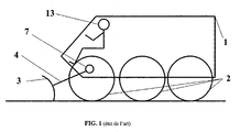
- Figure 1 is presented the state of the art.
- a civilian land development vehicle including a crate 1 is based on running gear 2 which can be tracked or wheeled as shown.
- Tool 3 here shown, for illustrative purposes, is a bulldozer blade.
- the support 4 linking the tool 3 to the body 1 of the vehicle is, in the state of the art, a single arm or equivalent. Such support 4 does not bring the tool closer or further away 3 1. At most one hinge 7 can allow the tool 3 to come down into contact with the ground or raise it.
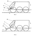
- Figures 2 and 3 illustrate an embodiment of a military terrain vehicle according to the invention.
- a vehicle comprising the body 1 rests on running gear 2.
- a driver 13, present on board of the vehicle provides control of the vehicle during the phases transport, as well as the use of tool 3 during phases of work.
- Tool 3 here represented, as illustrative, is a bulldozer blade.
- the support 4 binder the tool 3 at the body 1 of the vehicle comprises a jack telescopic 5 linked at one end to the body 1 and to the other end to the tool 3.
- Such a means 4, comprising a jack telescopic 5, when closed (see Figure 2), allows bring tool 3 closer to box 1 while reducing thus at least the jig in length of the military vehicle to constitute retractable means. this is particularly suitable for transport phases.
- this support 4 when is open (see Figure 3) this support 4, consisting of a telescopic jack 5, makes it possible to move the tool 3 away from the box 1 and thus place it in the field of view of the 13.
- support 4 is advantageously held in position by a locking means known to those skilled in the art.
- Tool 3 can then work in cooperation with the advance movement of the military vehicle.
- Fixing the support 4 at the level of the body 1 can include a hinge 7, if necessary motorized, allowing to vary the height of the tool compared on the ground.
- the device according to the invention is here shown seen from the side.
- the support 4 includes a telescopic jack 5 or more cylinders similar, placed parallel to one another, to the same height. They are therefore confused in a side view. he It goes without saying that these multiple cylinders 5 are maneuvered from concert.
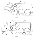
- FIG. 4 illustrates another mode of preferential realization of the military development vehicle field of the invention.
- the military vehicle comprising the body 1 rests on running gear 2.
- the driver 13 controls the vehicle and the tool 3 shown, for illustrative purposes, is a bulldozer blade.
- the support 4, linking the tool to the body 1 of the vehicle, comprises two half-arms 6 and 9.
- the first half-arm 6 is connected to a from its ends to the box 1 by means of a first articulation 7, and at the other end to a second half-arm 9 through a second hinge 8. Both half-arms constitute the retractable means.
- the other end of the second half-arm 9 carries the tool 3.
- the axes of the two joints 7 and 8 are substantially parallel between them.
- this support 4 allows the tool 3 to be moved away from the body 1 and placed there thus in the driver's field of vision 13. Once open, the support 4 is advantageously held in position by a blocking means known to those skilled in the art. Tool 3 can then work in cooperation with the movement in advance of the military vehicle.
- the device according to the invention is here shown from the side. Support 4 and mainly the first hinge 7 allow for more a height adjustment of the tool 3 relative to the ground.
- Figures 6 and 7 illustrate embodiments of the motorization of the articulated support 4 with two half-arms 6 and 9. It is conceivable not to envisage any motorization of the control of the support 4.
- the driver 13 can maneuver tool 3, both half-arms 6 and 9 by hand or by moving his military land development vehicle. Once the position of the desired tool 3 has been obtained, the driver 13 freezes this position by blocking joints 7, 8, by means known to those skilled in the art (not shown) It is advantageous to facilitate the task of the driver 13 by motorizing all or part of the support 4. It is thus possible to control the mobility independently of each articulation 7 or 8.
- FIG. 6 illustrates a first motorization 10 applied at the level of the first half-arm 6.
- This first motorization 10 can for example take two forms alternatives. It can be achieved by a rotary engine acting directly at the first joint 7. It can alternatively be performed by an actuator linear, for example of the cylinder type. One end of such actuator is integral with the body 1 and the second is integral with the first half-arm 6. The deployment or folding of such a linear actuator causes the rotation of the half-arm 6 around the first articulation 7.
- the FIG. 6 presents such a first motorization 10 in folded position for transport and figure 7 la represents in deployed position for landscaping work ground.
- the driver 13 uses the movement of the vehicle to position the tool 3. By acting on the half-arm 6 through the motorization 10 it can bring the tool 3 in contact with the ground. Backing-up then his military vehicle the driver 13 produces a opening of the angle between the half-arms 6 and 9. In contrast, by advancing the vehicle, it produces a closure of the same angle. It can thus mobilize the second articulation 8, the latter is not motorized.
- This second motorization 11 can take least two alternative forms. It can be done by a rotary motor acting directly at the level of the second articulation 8. It can alternatively be performed by a linear actuator, for example of the type cylinder. One end of such an actuator is integral with the half-arm 6 and the second is secured to the other half-arm 9. The deployment or refolding of such an actuator linear rotation causes the rotation of the half-arm 9 relative to the half-arm 6, around the second articulation 8.
- FIG. 6 has such a second motor 11 in position folded for transport and Figure 7 represents it in deployed position for land development work.
- tools 3 only worn by the vehicle.
- a drilling device is likely to be able to be away from the vehicle during use, in order to clear the driver's field of vision.
- another category of tools 3 consists of tools used in cooperation with the movement of advancement vehicle.
- a marking tool is soil, a spreading tool, a sweeping tool, a tool for cutting or cutting vegetation, a sanding tool, a snow removal cutter, a peel-off tool ground sheet.
- Another category of tools 3 is constituted by tools manipulated through the thrust effort produced by the advancement of the vehicle in response to contact with tool 3 with the field.
- non-orientable dozer blade tool a blade tool steerable dozer
- bucket loader tool bucket tool "4 in 1" (tool combining the functions of blade, bucket and taker)
- demining tool for example of the type push plow
- scarification tool a tool for grooving or a snow plow tool.
Landscapes
- Engineering & Computer Science (AREA)
- General Engineering & Computer Science (AREA)
- Mechanical Engineering (AREA)
- Mining & Mineral Resources (AREA)
- Civil Engineering (AREA)
- Structural Engineering (AREA)
- Body Structure For Vehicles (AREA)
- Aiming, Guidance, Guns With A Light Source, Armor, Camouflage, And Targets (AREA)
Applications Claiming Priority (2)
| Application Number | Priority Date | Filing Date | Title |
|---|---|---|---|
| FR0311091 | 2003-09-22 | ||
| FR0311091A FR2860015B1 (fr) | 2003-09-22 | 2003-09-22 | Vehicule militaire d'amenagement de terrain |
Publications (1)
| Publication Number | Publication Date |
|---|---|
| EP1516966A1 true EP1516966A1 (de) | 2005-03-23 |
Family
ID=34178937
Family Applications (1)
| Application Number | Title | Priority Date | Filing Date |
|---|---|---|---|
| EP04291957A Withdrawn EP1516966A1 (de) | 2003-09-22 | 2004-07-30 | Militärfahrzeug zum Anlegen von Geländen. |
Country Status (2)
| Country | Link |
|---|---|
| EP (1) | EP1516966A1 (de) |
| FR (1) | FR2860015B1 (de) |
Cited By (1)
| Publication number | Priority date | Publication date | Assignee | Title |
|---|---|---|---|---|
| EP1918461A1 (de) * | 2006-11-03 | 2008-05-07 | Rheinmetall Landsysteme GmbH | Fahrzeug mit einer bugseitig angeordneten Stütz- und Räumanlage |
Citations (9)
| Publication number | Priority date | Publication date | Assignee | Title |
|---|---|---|---|---|
| DE2501461A1 (de) | 1975-01-16 | 1976-07-22 | Porsche Ag | Bugschild fuer fahrzeuge, insbesondere fuer gelaendefahrzeuge |
| DE2632568A1 (de) * | 1976-07-20 | 1978-01-26 | Kaelble Gmbh C | Geraet zum raeumen von landminen |
| GB2220894A (en) | 1988-07-19 | 1990-01-24 | Jayauto Ltd | Adjustable tine depth mineplough |
| WO1998014748A1 (en) * | 1996-09-30 | 1998-04-09 | Hontiaske Strojarne, A.S. | A mine-disposal assembly and the way of its operating |
| DE19813542C1 (de) | 1998-03-27 | 1999-07-22 | Mak System Gmbh | Räum- und Stützschild |
| JP2000046496A (ja) | 1998-07-28 | 2000-02-18 | Toyo Constr Co Ltd | 地雷処理装置 |
| US20040020084A1 (en) * | 2000-05-26 | 2004-02-05 | Yves Riberon | Method for automatically moving on the ground a tool mounted at the end of an articulated arm |
| US6698478B2 (en) * | 2000-09-15 | 2004-03-02 | Les Equipments Nokamic, Inc. | Mobile silvicultural apparatus and method for operating the same |
| WO2004027163A1 (en) | 2002-04-11 | 2004-04-01 | Hopson, Donald G. | Bulldozer rear blade mounting apparatus |
-
2003
- 2003-09-22 FR FR0311091A patent/FR2860015B1/fr not_active Expired - Fee Related
-
2004
- 2004-07-30 EP EP04291957A patent/EP1516966A1/de not_active Withdrawn
Patent Citations (9)
| Publication number | Priority date | Publication date | Assignee | Title |
|---|---|---|---|---|
| DE2501461A1 (de) | 1975-01-16 | 1976-07-22 | Porsche Ag | Bugschild fuer fahrzeuge, insbesondere fuer gelaendefahrzeuge |
| DE2632568A1 (de) * | 1976-07-20 | 1978-01-26 | Kaelble Gmbh C | Geraet zum raeumen von landminen |
| GB2220894A (en) | 1988-07-19 | 1990-01-24 | Jayauto Ltd | Adjustable tine depth mineplough |
| WO1998014748A1 (en) * | 1996-09-30 | 1998-04-09 | Hontiaske Strojarne, A.S. | A mine-disposal assembly and the way of its operating |
| DE19813542C1 (de) | 1998-03-27 | 1999-07-22 | Mak System Gmbh | Räum- und Stützschild |
| JP2000046496A (ja) | 1998-07-28 | 2000-02-18 | Toyo Constr Co Ltd | 地雷処理装置 |
| US20040020084A1 (en) * | 2000-05-26 | 2004-02-05 | Yves Riberon | Method for automatically moving on the ground a tool mounted at the end of an articulated arm |
| US6698478B2 (en) * | 2000-09-15 | 2004-03-02 | Les Equipments Nokamic, Inc. | Mobile silvicultural apparatus and method for operating the same |
| WO2004027163A1 (en) | 2002-04-11 | 2004-04-01 | Hopson, Donald G. | Bulldozer rear blade mounting apparatus |
Non-Patent Citations (1)
| Title |
|---|
| PATENT ABSTRACTS OF JAPAN vol. 2000, no. 05 14 September 2000 (2000-09-14) * |
Cited By (1)
| Publication number | Priority date | Publication date | Assignee | Title |
|---|---|---|---|---|
| EP1918461A1 (de) * | 2006-11-03 | 2008-05-07 | Rheinmetall Landsysteme GmbH | Fahrzeug mit einer bugseitig angeordneten Stütz- und Räumanlage |
Also Published As
| Publication number | Publication date |
|---|---|
| FR2860015B1 (fr) | 2006-12-22 |
| FR2860015A1 (fr) | 2005-03-25 |
Similar Documents
| Publication | Publication Date | Title |
|---|---|---|
| CA2535238C (fr) | Engin agricole pour la coupe de produits | |
| US5638908A (en) | Apparatus for adjusting between crawler tracks of a working vehicle | |
| US8776406B2 (en) | Reversible wing plow and method of rotation | |
| US20170342682A1 (en) | Vehicle With Non-Symmetrical Drive Members | |
| CA2174789A1 (fr) | Engin de travaux publics dont l'outil de travail est monte a l'extremite d'un bras articule | |
| EP2154294A1 (de) | Verlängerbares Räumschild | |
| CA2299070A1 (en) | Self-powered brush cutter | |
| EP0839443B1 (de) | Mähmaschine | |
| EP1516966A1 (de) | Militärfahrzeug zum Anlegen von Geländen. | |
| WO2016207511A1 (fr) | Equipement de nettoyage, notamment de fosse, et ensemble comprenant un tel equipement de nettoyage | |
| EP1632638B1 (de) | Hydraulische Bohrvorrichtung um in beengte Räumlichkeiten zu arbeiten | |
| FR2701627A1 (fr) | Dispositif adaptable sur véhicule automoteur du genre tracteur, notamment pour l'entretien des espaces verts, talus et accotements. | |
| EP2617278B1 (de) | Landwirtschaftliches Gerät für ein motorisiertes Fahrzeug mit verformbarem Parallelogramm zur seitlichen Versetzung eines Werkzeugteils | |
| WO2006079735A1 (fr) | Faucheuse avec un dispositif de depliage et de repliage perfectionne | |
| EP1527671B1 (de) | Mäher oder Häcksler, der an einem selbstfahrenden traktorartigen Fahrzeug anbringbar ist | |
| FR2758228A1 (fr) | Machine agricole, en particulier de preparation du sol et de dechaumage comportant des moyens d'entrainement en pivotement des trains porteurs d'outils | |
| EP4317760B1 (de) | Selbstfahrende rollende maschine, insbesondere zum aufbringen von schüttgut für strassenbeläge auf den boden | |
| FR2718169A1 (fr) | Engin de façonnage et/ou de remise en état de bas-côtés. | |
| FR2854121A1 (fr) | Dispositif de tracteur enjambeur | |
| EP2397395B1 (de) | Selbstfahrender Werkzeugträgerwagen mit 4 asymmetrischen Rädern | |
| US5234284A (en) | Wheeled road surface cutter | |
| FR3032595A1 (fr) | Machine de coupe de vegetaux et vehicule automobile comprenant une telle machine de coupe | |
| US20060070754A1 (en) | Steerable attachment for equipment | |
| EP4381932A1 (de) | Schneidvorrichtung für vegetation | |
| FR2623830A1 (fr) | Dispositif chasse-neige monte sur un vehicule |
Legal Events
| Date | Code | Title | Description |
|---|---|---|---|
| PUAI | Public reference made under article 153(3) epc to a published international application that has entered the european phase |
Free format text: ORIGINAL CODE: 0009012 |
|
| AK | Designated contracting states |
Kind code of ref document: A1 Designated state(s): AT BE BG CH CY CZ DE DK EE ES FI FR GB GR HU IE IT LI LU MC NL PL PT RO SE SI SK TR |
|
| AX | Request for extension of the european patent |
Extension state: AL HR LT LV MK |
|
| RIN1 | Information on inventor provided before grant (corrected) |
Inventor name: BERTRAND, LUDOVIC Inventor name: ORGELET, SERGE |
|
| 17P | Request for examination filed |
Effective date: 20050914 |
|
| AKX | Designation fees paid |
Designated state(s): AT BE BG CH CY CZ DE DK EE ES FI FR GB GR HU IE IT LI LU MC NL PL PT RO SE SI SK TR |
|
| RAP1 | Party data changed (applicant data changed or rights of an application transferred) |
Owner name: NEXTER SYSTEMS |
|
| 17Q | First examination report despatched |
Effective date: 20070924 |
|
| STAA | Information on the status of an ep patent application or granted ep patent |
Free format text: STATUS: THE APPLICATION HAS BEEN WITHDRAWN |
|
| 18W | Application withdrawn |
Effective date: 20100319 |