EP1516822A2 - Blank and associated container - Google Patents
Blank and associated container Download PDFInfo
- Publication number
- EP1516822A2 EP1516822A2 EP04255569A EP04255569A EP1516822A2 EP 1516822 A2 EP1516822 A2 EP 1516822A2 EP 04255569 A EP04255569 A EP 04255569A EP 04255569 A EP04255569 A EP 04255569A EP 1516822 A2 EP1516822 A2 EP 1516822A2
- Authority
- EP
- European Patent Office
- Prior art keywords
- blank
- container
- cover
- access flap
- base
- Prior art date
- Legal status (The legal status is an assumption and is not a legal conclusion. Google has not performed a legal analysis and makes no representation as to the accuracy of the status listed.)
- Withdrawn
Links
- 230000001419 dependent effect Effects 0.000 claims 6
- 239000003292 glue Substances 0.000 abstract description 18
- 238000000034 method Methods 0.000 abstract description 10
- 239000000463 material Substances 0.000 description 3
- 230000015572 biosynthetic process Effects 0.000 description 2
- 238000010276 construction Methods 0.000 description 1
- 230000000694 effects Effects 0.000 description 1
- 238000009877 rendering Methods 0.000 description 1
- 230000000284 resting effect Effects 0.000 description 1
Images


Classifications
-
- B—PERFORMING OPERATIONS; TRANSPORTING
- B65—CONVEYING; PACKING; STORING; HANDLING THIN OR FILAMENTARY MATERIAL
- B65D—CONTAINERS FOR STORAGE OR TRANSPORT OF ARTICLES OR MATERIALS, e.g. BAGS, BARRELS, BOTTLES, BOXES, CANS, CARTONS, CRATES, DRUMS, JARS, TANKS, HOPPERS, FORWARDING CONTAINERS; ACCESSORIES, CLOSURES, OR FITTINGS THEREFOR; PACKAGING ELEMENTS; PACKAGES
- B65D5/00—Rigid or semi-rigid containers of polygonal cross-section, e.g. boxes, cartons or trays, formed by folding or erecting one or more blanks made of paper
- B65D5/02—Rigid or semi-rigid containers of polygonal cross-section, e.g. boxes, cartons or trays, formed by folding or erecting one or more blanks made of paper by folding or erecting a single blank to form a tubular body with or without subsequent folding operations, or the addition of separate elements, to close the ends of the body
- B65D5/16—Rigid or semi-rigid containers of polygonal cross-section, e.g. boxes, cartons or trays, formed by folding or erecting one or more blanks made of paper by folding or erecting a single blank to form a tubular body with or without subsequent folding operations, or the addition of separate elements, to close the ends of the body the tubular body being formed with an aperture or removable portion arranged to allow removal or insertion of contents through one or more sides
-
- B—PERFORMING OPERATIONS; TRANSPORTING
- B65—CONVEYING; PACKING; STORING; HANDLING THIN OR FILAMENTARY MATERIAL
- B65D—CONTAINERS FOR STORAGE OR TRANSPORT OF ARTICLES OR MATERIALS, e.g. BAGS, BARRELS, BOTTLES, BOXES, CANS, CARTONS, CRATES, DRUMS, JARS, TANKS, HOPPERS, FORWARDING CONTAINERS; ACCESSORIES, CLOSURES, OR FITTINGS THEREFOR; PACKAGING ELEMENTS; PACKAGES
- B65D5/00—Rigid or semi-rigid containers of polygonal cross-section, e.g. boxes, cartons or trays, formed by folding or erecting one or more blanks made of paper
- B65D5/42—Details of containers or of foldable or erectable container blanks
- B65D5/54—Lines of weakness to facilitate opening of container or dividing it into separate parts by cutting or tearing
- B65D5/5405—Lines of weakness to facilitate opening of container or dividing it into separate parts by cutting or tearing for opening containers formed by erecting a blank in tubular form
- B65D5/542—Lines of weakness to facilitate opening of container or dividing it into separate parts by cutting or tearing for opening containers formed by erecting a blank in tubular form the lines of weakness being provided in the container body
-
- B—PERFORMING OPERATIONS; TRANSPORTING
- B65—CONVEYING; PACKING; STORING; HANDLING THIN OR FILAMENTARY MATERIAL
- B65D—CONTAINERS FOR STORAGE OR TRANSPORT OF ARTICLES OR MATERIALS, e.g. BAGS, BARRELS, BOTTLES, BOXES, CANS, CARTONS, CRATES, DRUMS, JARS, TANKS, HOPPERS, FORWARDING CONTAINERS; ACCESSORIES, CLOSURES, OR FITTINGS THEREFOR; PACKAGING ELEMENTS; PACKAGES
- B65D5/00—Rigid or semi-rigid containers of polygonal cross-section, e.g. boxes, cartons or trays, formed by folding or erecting one or more blanks made of paper
- B65D5/42—Details of containers or of foldable or erectable container blanks
- B65D5/54—Lines of weakness to facilitate opening of container or dividing it into separate parts by cutting or tearing
- B65D5/5445—Lines of weakness to facilitate opening of container or dividing it into separate parts by cutting or tearing for dividing a tubular body into separate parts
Definitions
- the access flap comprises first and second portions, the first portion being connected to the second, cover part of the blank by a first crease and the second portion being connected to the first portion by a second crease parallel to the first, thereby allowing the first, base part of the blank to be partially superimposed upon the second, cover part of the blank.
- an aperture in the access flap enables the cover, together with the access flap, to be removed from the base of the container in a single manual operation by inserting a finger into the aperture and lifting the cover upwardly away from the base.
- the access flap has at least one aperture formed therein to enable the flap to be manually gripped for detaching the cover from the base of the container.
- the access flap may have at least one aperture formed therein to enable the flap to be manually gripped for detaching the cover from the base of a container erected from the partially erected blank.
- the aperture is located at a position in the access flap on the partially erected blank such that it is partially overlapped by the first portion of the access flap when the cover of the container is partially superimposed upon the base such that the aperture provides manual access to an edge of the cover.
- a glue assembly flap 134 At the right hand end of the second, cover part 112 of the blank is provided a glue assembly flap 134, whilst at the opposite, left hand end of the first, base part 110 is provided yet another glue assembly flap 136.
- FIG. 6 A second embodiment of the blank and a container erected therefrom in accordance with the invention are shown in figures 6 to 10 of the accompanying drawings.
- the second embodiment of the blank in accordance with the invention has a generally similar construction to that of the first embodiment and therefore in the following description of the second embodiment like numerals to those employed in the description of the first embodiment will be employed to denote like parts but preceded by the numeral "3".
- the blank 3100 has first and second parts 3110, 3112, corresponding respectively to the base 3210 and cover 3212 of the erected container 3200, as shown in figure 9.
- the first and second parts 3110, 3112 are separated by a cut 3114 in the blank 3100 which extends on either side of an access flap 3116 integral to the second, cover part 3212.
- the first and second parts 3110, 3112 are connected together by the access flap 3116 and optionally also by a hinge assembly 3113 which is located to the rear of the cover 3212 of the erected container 3200.
- the optional hinge assembly 3113 comprises a hinge member 3113a connected to the second, cover part 3112 by a double crease 3117 and to the first, base part 3110 by a reverse crease or perforation 3119.
- An aperture 3137 is provided in the first, base part 3110 adjacent the hinge member 3113a.
- Vertically extending perforated lines 3121 aligned with side edges of the hinge member 3113a may be provided in the cover part 3112 immediately above said hinge member 3113a.
- the perforated lines 3119 are joined by a horizontal perforated or fold line 3125 spaced from and parallel to the crease line 3117.
- the access flap 3116 and optional hinge member 3113a are creased such that the first, base part 3110 of the blank 3100 can be partially superimposed upon the second, cover part 3112 during a first stage (depicted in figure 7) of erecting the container 3200 from the blank 3100.
- This is achieved by folding the first upper portion 3118 of the access flap 3116 to lie behind the second lower portion 3112 of said flap 3116 and, where included as part of the blank 3100, folding the hinge member 3113a to lie behind a corresponding part of the first, base part 3110 as they are viewed in figures 6 & 7.
- the blank 3100 includes means 4000 by which the partially formed blank (figures 7 and 8) and/or container (figure 9) can be machine handled for assembly.
- the access flap 3116 is formed to be integral with the cover part 3112 of the blank 3100 and is connected to the base part 3110 by a perforated line 3126 that enables said flap 3116 to be manually removed from the base part, in use.
- the access flap 3116 is formed to extend down a front or side panel 3142 of the base part 3110 that will form a front end face 3142 of the container 3200 upon erection thereof.
Landscapes
- Engineering & Computer Science (AREA)
- Mechanical Engineering (AREA)
- Cartons (AREA)
Abstract
Description
- This invention relates to a blank, and an associated container, for use in the storage, transportation and display of a product, the container comprising a base and a cover, which are erectable from the blank and which are detachably secured together on erection of the blank for storage and transportation purposes, but which can be separated at a point-of-sale to display a product or products contained in the base.
- Applicants co-pending United Kingdom patent application number 0314144.7 filed on the 18th of June 2003 discloses a blank and an associated container comprising a base and a cover with respective closure flaps and glue assembly flaps. The blank comprises first and second parts corresponding respectively to the base and cover of the container erectable therefrom. The first and second parts are connected together by at least one tear-off flap.
- In one embodiment, a tear-out access flap is provided in a panel of the first, base part of the blank. This removable access panel is connected detachably to the first, base part by a suitable perforation or other weakened line. Prior to the first, base part of the blank being partially superimposed upon the second, cover part of the blank, glue is applied to a region on the underside of the tear-out access flap and/ or a region on an upper side of the adjacent panel of the second, cover part of the blank. When the first, base part of the blank is partially superimposed upon the second, cover part, the tear-out access flap of the first, base part is adhered to the second, cover part. Thus, when the fully erected, product filled container erected from the blank has its cover removed at a point-of-sale, the tear-out access flap is also removed from the base by rupture of the perforation or other weakened line, thus providing access to the product in the base.
- It is, however, necessary to remove the at least one tear-off flap to enable removal of the cover of the container together with the tear-out access flap.
- The requirement to apply glue to one or both of a region on the underside of the tear-out access flap of the first, base part of the blank and a region on an upper side of the adjacent panel of the second, cover part of the blank comprises an additional process step in the formation of a partially erected blank.
- It is an object of the present invention to eliminate such additional process steps.
- It is also an object of the present invention to improve the structure of a blank for erecting a container of the type aforesaid and to mitigate or obviate other disadvantages associated with containers of this and a like kind.
- According to a first aspect of the invention, there is provided a blank erectable into a generally rectangular container comprising a base and a cover with respective closure flaps and attachment flaps, the blank comprising first and second parts corresponding respectively to the base and cover of the container erectable therefrom, the first and second parts being connected by an access flap formed integrally with the second part, which is detachably connected to the first part.
- By forming the access flap to be integral with the second, cover part of the blank, this negates the need for the additional glue application process in the formation of the partially erect blank as disclosed in applicant's aforementioned co-pending patent application.
- Further, applicant has been surprised to discover that, by forming the access flap integrally with the second, cover part of the blank, it is possible to employ only the access flap to secure the cover to the base of the container without the need to also employ tear-off flaps as disclosed in applicant's aforementioned co-pending patent application.
- Preferably, the access flap is detachably connected to the first, base part of the blank by a perforation or other weakened line.
- Preferably also, the access flap is located on the blank such that it forms a front panel of the container erected from the blank.
- This provides easy access to product contained within the container when the cover, together with the access flap, is removed from the base.
- Preferably, the access flap comprises first and second portions, the first portion being connected to the second, cover part of the blank by a first crease and the second portion being connected to the first portion by a second crease parallel to the first, thereby allowing the first, base part of the blank to be partially superimposed upon the second, cover part of the blank.
- Preferably also, the access flap has at least one aperture formed therein to enable the flap to be manually gripped for detaching the cover from the base of a container erected from the blank.
- The aperture provides a means by which the cover of the container can be more readily manually engaged to remove it than that provided by an edge of the cover formed by its partial superimposition on the base.
- Also, the provision of an aperture in the access flap enables the cover, together with the access flap, to be removed from the base of the container in a single manual operation by inserting a finger into the aperture and lifting the cover upwardly away from the base.
- Preferably, the aperture is located in the access flap on the blank such that it is adjacent to an edge formed by the first portion of the access flap when the cover of the container erected from the blank is partially superimposed upon the base.
- Preferably also, the aperture is located at a position in the access flap on the blank such that it is partially overlapped by the first portion of the access flap when the cover of the container is partially superimposed upon the base such that the aperture provides manual access to an edge of the cover.
- Positioning the aperture at a position on the access flap such that it is partially overlapped by the cover of the container provides manual access to an edge of the cover which, by virtue of the partial superimposition of the cover upon the base, comprises a double thickness of the material forming the blank and is thus a good place to apply manual pressure to effect removal of the cover from the base..
- Preferably, the access flap extends substantially the depth of the first, base part of the blank.
- Preferably also, cutaway regions are provided in the blank adjacent to and on each side of the first portion of the access flap, wherein the cutaway regions extend at least the depth of said first portion.
- The cutaway regions ease the partial superimposition of the first, base part of the blank upon the second, cover part thereof.
- According to a second aspect of the invention, there is provided a container of generally rectangular form comprising a base and a cover, the cover being superimposed on the base to partially envelop the base, the base and cover being formed from respective first and second parts of a container blank and being connected by an access flap formed integrally with the cover, said flap being detachably connected to said base.
- Preferably, the access flap is detachably connected to the base of the container by a perforation or other weakened line.
- Preferably also, the access flap forms a front panel of the container.
- The access flap may comprise first and second portions, the first portion being connected to the cover of the container by a first crease and the second portion being connected to the first portion by a second crease parallel to the first and being detachably connected to the base of the container, the first portion of the access flap being superimposed upon an upper part of said second portion.
- Advantageously, the access flap has at least one aperture formed therein to enable the flap to be manually gripped for detaching the cover from the base of the container.
- Preferably, the aperture is located in the access flap such that it is adjacent to an edge formed by the first portion of the access flap superimposed upon an upper part of said second portion.
- The aperture may be located at a position in the access flap such that it is partially overlapped by the first portion of the access flap in order to provide manual access to an edge of the cover.
- Preferably, the access flap extends substantially the depth of the base.
- According to a third aspect of the invention, there is provided a partially erected blank erectable into a generally rectangular container comprising a base and a cover with respective closure flaps and attachment flaps, the partially erected blank comprising first and second parts corresponding respectively to the base and cover of the container erectable therefrom, the first and second parts being connected by an access flap formed integrally with the second part, which is detachably connected to the first part, wherein the first and second parts are each folded with their respective attachment flaps secured to respective attachment portions located at opposed ends of said parts.
- Preferably, the access flap is detachably connected to the first, base part of the partially erected blank by a perforation or other weakened line.
- The access flap may be located on the partially erected blank such that it forms a front panel of the container erected from said blank.
- Preferably, the access flap comprises first and second portions, the first portion being connected to the second, cover part of the partially erected blank by a first crease and the second portion being connected to the first portion by a second crease parallel to the first, thereby allowing the first, base part of the blank to be partially superimposed upon the second, cover part of the blank.
- The access flap may have at least one aperture formed therein to enable the flap to be manually gripped for detaching the cover from the base of a container erected from the partially erected blank.
- The aperture may be located in the access flap on the partially erected blank such that it is adjacent to an edge formed by the first portion of the access flap when the cover of the container erected from the blank is partially superimposed upon the base.
- Preferably, the aperture is located at a position in the access flap on the partially erected blank such that it is partially overlapped by the first portion of the access flap when the cover of the container is partially superimposed upon the base such that the aperture provides manual access to an edge of the cover.
- The access flap may extend substantially the depth of the first, base part of the partially erected blank.
- The foregoing, and further features of the invention will be more readily understood from the following description of preferred embodiments, by way of example thereof, with reference to the accompanying drawings of which:
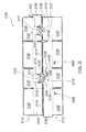
- Figure 1 is an inside plan view of a first embodiment of blank in accordance with the invention;
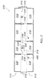
- Figure 2 is an inside plan view of a partially erected form of the blank of figure 1;
- Figure 3 is an external plan view of a further, partially erected form of the blank of figure 1;
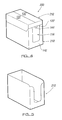
- Figure 4 is a perspective view not to scale of a container formed from a blank in accordance with the first embodiment of the invention;
- Figure 5 is a perspective view not to scale of the base of a container erected from a blank in accordance with the first embodiment of the invention, with the cover of the container removed;
- Figure 6 is an inside plan view of a second embodiment of blank in accordance with the invention;
- Figure 7 is an inside plan view of a partially erected form of the blank of figure 6;
- Figure 8 is an enlarged external plan view of a further, partially erected form of the blank of figure 6;
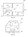
- Figure 9 is an end-on perspective view not to scale of a container formed from a blank in accordance with the second embodiment of the invention; and
- Figure 10 is a perspective view not to scale of the base of a container erected from a blank in accordance with the second embodiment of the invention, with the cover of the container removed.
-
- A first embodiment of the blank and a container erected therefrom in accordance with the invention are shown in figures 1 to 5 of the accompanying drawings.
- The blank 100 has first and
second parts base 210 and cover 212 of the erectedcontainer 200, as shown in figure 4. The first andsecond parts cut 114 in the blank 100 which extends on either side of anaccess flap 116 integral to the second, cover part. The first andsecond parts access flap 116. Theaccess flap 116 comprises afirst portion 118 connected to the second, coverpart 112 by adouble crease 120 and asecond portion 122 connected to thefirst portion 118 by areverse crease 124. Thesecond portion 122 is connected to the first,base part 110 by aperforated line 126 which extends betweencutaway regions 128 located to either of thefirst portion 118 of theaccess flap 116. - Thus, the
access flap 116 is creased such that the first,base part 110 of the blank 100 can be partially superimposed upon the second, coverpart 112 during a first stage (depicted in figure 2) of erecting thecontainer 200 from the blank 100. This is achieved by folding thefirst portion 118 of theaccess flap 116 to lie behind anupper part 122a of the second portion of saidflap 116 as it is viewed in figures 1 & 2. - The manner by which such superimposition can be achieved is well understood by a skilled artisan and need not be discussed here.
-
Closure flap panels base part 110 and the second, coverpart 112 of the blank 100 which constitute lower (not shown) and upper (some shown) closure flaps of the finally erected container (see figure 4). - At the right hand end of the second, cover
part 112 of the blank is provided aglue assembly flap 134, whilst at the opposite, left hand end of the first,base part 110 is provided yet anotherglue assembly flap 136. - Upon erection of the blank, and after the first,
base part 110 has been partially superimposed upon the second, coverpart 112, glue can be applied to the glue assembly flaps 134, 136 and/or corresponding portions 134', 136' at opposed ends of theparts - Now, the partially erected blank 100' (figure 2) can be folded about
normal creases 138 of the first andsecond parts - Assembling the partially erect blank 100" (figure 3) by means of adhering together assembly flaps in the manner aforedescribed is the preferred method of forming said partially erected blank, but it will be understood by a skilled artisan that other known methods of securing assembly flaps to corresponding portions of blanks such as stapling, for example, may be employed and therefore the preferred method described herein is not to be considered as limiting the scope of the invention.
- The partially erect blank 100" of the form depicted in figure 3 is in a flat form ideal for being shipped to manufacturers of product that can be.placed in the containers erectable from the blanks for transport of such product to a point-of-sale.
- A
container 200 is erected from the partially erect blank 100" depicted by figure 3 by folding about furthernormal creases 140 such that the blank 100" takes a generally rectangular form. After the bottom closure flaps 130 have been closed in a conventional manner, the container is ready to be filled with, say, a loose product prior to the top closure flaps 132 of the cover being closed. - In this manner, a product-filled
container 200 is provided, with itscover 212 detachably secured to itsbase 210 for storage and/or transportation purposes. - Referring again to figures 1 & 2, it can be seen that the
access flap 116 is formed to be integral with thecover part 112 of the blank 100 and is connected to thebase part 110 by aperforated line 126 that enables saidflap 116 to be manually removed from the base part, in use. Theaccess flap 116 is formed to extend substantially down apanel 142 of thebase part 110 that will form afront end face 142 of thecontainer 200 upon erection thereof. Thus, theaccess flap 116 not only performs the task of securing thecover 212 to thebase 210 of acontainer 200 erected from the blank 100 but also provides an access to product stored in the container when said container is displayed at a point-of-sale and its cover together with the access flap has been removed (figure 5). - The
access flap 116 has anaperture 144 formed in it to allow it to be gripped by a person inserting one of more fingers through theaperture 144. It will be understood that theflap 116 may be formed with a plurality of such apertures. In the preferred embodiment as depicted in the drawings, theaperture 144 is located on the blank such that, when the container is erected, thecover 212 partially overlaps (figure 4) theaperture 144. The aperture thus provides manual access to an edge 120' of the cover formed by folding thefirst portion 118 of theaccess flap 116 to lie behind anupper portion 122a thereof as depicted in figure 2 or in front of saidupper portion 122a as depicted in figures 4 & 5. The part of the cover so formed comprises a double thickness of the material from which the blank 100 is formed which strengthens said edge 120' and renders it an ideal point for applying manual pressure to the cover to detach it together with the access flap from the base. - It will be noted that the blank 100 is formed with
cutaway regions 128 to either side of thefirst portion 118 of theaccess flap 116 and which extend for at least the depth of saidfirst portion 118. Thecutaway regions 128 assist the ease with which thebase part 110 of the blank 100 can be partially superimposed upon thecover part 112 when forming the partially erected blank 100' depicted by figure 2. - A second embodiment of the blank and a container erected therefrom in accordance with the invention are shown in figures 6 to 10 of the accompanying drawings. The second embodiment of the blank in accordance with the invention has a generally similar construction to that of the first embodiment and therefore in the following description of the second embodiment like numerals to those employed in the description of the first embodiment will be employed to denote like parts but preceded by the numeral "3".
- The blank 3100 has first and
second parts base 3210 and cover 3212 of the erectedcontainer 3200, as shown in figure 9. The first andsecond parts cut 3114 in the blank 3100 which extends on either side of anaccess flap 3116 integral to the second, coverpart 3212. The first andsecond parts access flap 3116 and optionally also by ahinge assembly 3113 which is located to the rear of thecover 3212 of the erectedcontainer 3200. - The
access flap 3116 comprises a first upper portion 3118 connected to the second, coverpart 3112 by adouble crease 3120 and a second lower portion 3122 connected to the first upper portion 3118 by a reverse crease orperforation 3124. The second lower portion 3122 is connected to the first,base part 3110 by aperforated line 3126 such that theaccess flap 3116 can be detached from thebase 3210 of the erected container 3200 (figure 9). The lower portion 3122 has anaperture 3135 through which a finger can be inserted. Vertically extendingperforated lines 3115 aligned with side edges of the first upper portion 3118 of theaccess flap 3116 may be provided in thecover part 3112 immediately above said upper portion 3118. Theperforated lines 3115 are joined by a horizontal perforated or foldline 3111 spaced from and parallel with thedouble crease 3120. - The
optional hinge assembly 3113 comprises a hinge member 3113a connected to the second, coverpart 3112 by adouble crease 3117 and to the first,base part 3110 by a reverse crease orperforation 3119. Anaperture 3137 is provided in the first,base part 3110 adjacent the hinge member 3113a. Vertically extendingperforated lines 3121 aligned with side edges of the hinge member 3113a may be provided in thecover part 3112 immediately above said hinge member 3113a. Theperforated lines 3119 are joined by a horizontal perforated or foldline 3125 spaced from and parallel to thecrease line 3117. - Thus, the
access flap 3116 and optional hinge member 3113a are creased such that the first,base part 3110 of the blank 3100 can be partially superimposed upon the second, coverpart 3112 during a first stage (depicted in figure 7) of erecting thecontainer 3200 from the blank 3100. This is achieved by folding the first upper portion 3118 of theaccess flap 3116 to lie behind the secondlower portion 3112 of saidflap 3116 and, where included as part of the blank 3100, folding the hinge member 3113a to lie behind a corresponding part of the first,base part 3110 as they are viewed in figures 6 & 7. - The blank 3100 includes
means 4000 by which the partially formed blank (figures 7 and 8) and/or container (figure 9) can be machine handled for assembly. -
Closure flap panels base part 110 and the second, coverpart 112 respectively of the blank 100 which constitute lower (not shown) and upper (some shown) closure flaps of the finally erected container (see figure 9). - At the right hand end of the second, cover
part 3112 of the blank is provided aglue assembly flap 3134, whilst at the opposite, left hand end of the first,base part 3110 is provided yet anotherglue assembly flap 3136. - Upon erection of the blank, and after the first,
base part 3110 has been partially superimposed upon the second, coverpart 3112, glue can be applied to the glue assembly flaps 3134, 3136 and/or corresponding portions 3134', 3136' at opposite ends of theparts - Now, the partially erected blank 3100' (figure 7) can be folded about
normal creases 3138 of the first andsecond parts - The partially erect blank 3100" of the form depicted in figure 8 is in a flat form ideal for being shipped to manufacturers of product that can be placed in the containers erectable from the blanks for transport of such product to a point-of-sale.
- A
container 3200 is erected from the partially erect blank 3100" depicted by figure 8 by folding about furthernormal creases 3140 such that the blank 3100" takes a generally rectangular form. After the bottom closure flaps 3130 have been closed in a conventional manner, the container is ready to be filled with, say, a loose product prior to the top closure flaps 132 of the cover being closed. - In this manner, a product-filled
container 3200 is provided, with itscover 3212 detachably secured to itsbase 3210 for storage and/or transportation purposes. - Referring again to figures 6 & 7, it can be seen that the
access flap 3116 is formed to be integral with thecover part 3112 of the blank 3100 and is connected to thebase part 3110 by aperforated line 3126 that enables saidflap 3116 to be manually removed from the base part, in use. Theaccess flap 3116 is formed to extend down a front orside panel 3142 of thebase part 3110 that will form afront end face 3142 of thecontainer 3200 upon erection thereof. Thus, theaccess flap 3116 not only performs the task of securing thecover 3212 to thebase 210 of acontainer 3200 erected from the blank 100 but also provides an access to product stored in the container when said container is displayed at a point-of-sale after its cover together with the access flap has been removed (figure 10). - When the
container 3200 is erected, thecover 3212 wholly encloses thebase 3210, although in a not shown embodiment, thecover 3212 is arranged such that its sides only partially overlap the sides of the base 3120 as in the first embodiment. - In the erected
container 3200, the upper portion 3118 of theaccess flap 3116 is superimposed on, i.e. overlies, thelower portion 3112 of the flap but is itself hidden from view being located behind a corresponding part of thecover 3212 bounded by theperforated lines 3115. This part of the cover therefore comprises a double thickness of the material from which the blank 3100 is formed rendering it an ideal point for applying manual pressure to thecover 3212 to detach it together with theaccess flap 3116 from thebase 3210. Initial manual pressure applied to theleading edge 3120 of thecover 3212 causes theperforated lines 3115 to break allowing the double thickness part (including the upper portion 3118 of the flap 3116) of thecover 3212 to swing upwardly in a direction away from thebase 3210. This part thus provides a means which can be easily manually gripped for applying further manual pressure to remove thecover 3212 from thebase 3210. The upturned double thickness part of the cover partially uncovers the access flaplower portion 3112 including its finger hole (aperture) 3135. - The cover of the container can be removed from the base in a number of ways after performing the initial step of upturning the double thickness part away from the base. In a first method, the double thickness part is detached from the
cover 3212 andaccess flap 3116 by breaking theperforations finger hole 3135 and the access flaplower portion 3112 removed by pulling it from thebase 3210 of the container. Thecover 3212 of the container can then be lifted from the base. Where the container includes a hinge assembly 31113, the hinge member 3113a can be removed from the base and cover in a similar manner thereby releasing a back part of the cover from the base. - Alternative methods of removing the cover from the base of the container include applying further manual pressure upwardly to the upturned double thickness part of the cover. This may be sufficient to cause the
perforated line 3126 to break thereby releasing theaccess flap 3116 from thebase 3210 of thecontainer 3200 and enabling the cover to be removed from the base in a single action. Alternatively, thelower portion 3112 of theflap 3116 which is now substantially exposed may be pressed manually inwardly to cause braking of theperforated line 3126 and then further manual pressure applied upwardly to the upturned double thickness part of thecover 3212 to remove thecover 3212 from thebase 3210 of thecontainer 3200 in a single action. As a further alternative, theperforated line 3111 of the upturned double thickness part may be manually broken to release the double thickness part from the cover whereby by then manually pulling said part outwardly and downwardly causes theperforated line 3126 to break releasing the access flap from thebase 3210 of the container. In this latter alternative, the cover will still be resting on the base but can be easily lifted therefrom to open the container and fully uncover the access passage previously sealed by the access flaplower portion 3112. - In summary, the present invention relates to a blank, and an associated container, for use in the storage, transportation and display of a product. The container comprises a base and a cover, which are erectable from the blank and which are detachably secured together on erection of the blank for storage and transportation purposes. The cover can be detached from the base at a point-of-sale to display a product or products contained in the base. The container of the invention is formed from a blank in which first and second parts corresponding to the base and cover of the container erectable therefrom are connected together by an access flap that is integral to the second, cover part of the blank and is detachably connected to the first, base part of the blank. A container formed from such a blank negates the need to glue the access flap to the cover part of the blank in a separate process step for forming a partially erected blank and may enable the cover and access flap of the container to be removed in a single manual operation.
Claims (31)
- A blank (100) erectable into a generally rectangular container (200) comprising a base (210) and a cover (212) with respective closure flaps (130,132) and attachment flaps (134,136), the blank (100) comprising first and second parts (110,112) corresponding respectively to the base (210) and cover (212) of the container (200) erectable therefrom, the first and second parts (110,112) being connected by an access flap (116) formed integrally with the second part (112), wherein the access flap (116) is detachably connected to the first part (110).
- A blank (100) as claimed in claim 1, wherein the access flap (116) is detachably connected to the first, base part (110) of the blank (100) by a perforation or other weakened line (126).
- A blank (100) as claimed in claim 1 or claim 2, wherein the access flap (116) is located on the blank (100) such that it forms a front or side panel (142) of the container (200) erected from the blank (100).
- A blank (100) as claimed in any preceding claim, wherein the access flap (116) comprises first and second portions (118,122), the first portion (118) being connected to the second, cover part (112) of the blank (100) by a first crease (120) and the second portion (122) being connected to the first portion (118) by a second crease (124) parallel to the first (120), thereby allowing the first, base part (110) of the blank (100) to be partially superimposed upon the second, cover part (112) of the blank.
- A blank (100) as claimed in any preceding claim, wherein the access flap (116) has at least one aperture (144) formed therein to enable the flap (116) to be manually gripped for detaching the access flap (116) and/or cover (212) from the base (210) of a container (200) erected from the blank (100).
- A blank (100) as claimed in any preceding claim, wherein the access flap (116) is also detachably connected to the second part (112).
- A blank (100) as claimed in claim 6, wherein a first portion (118) of the access flap (116) and a corresponding part of the cover part (112) of the blank (100) are provided with perforations (120) to enable said first portion (118) and/or corresponding part to be detached from the container (200) erected from the blank (100).
- A blank (100) as claimed in claim 5 when dependent on claim 4, wherein the aperture (144) is located in the access flap (116) on the blank (100) such that it is adjacent an edge formed by the first portion (118) of the access flap (116) when the cover (212) of the container (200) erected from the blank (100) is partially superimposed upon the base (210).
- A blank (100) as claimed in claim 5 when dependent on claim 4, wherein the aperture (144) is located at a position in the access flap (116) on the blank (100) such that it is partially overlapped by the first portion (118) of the access flap (116) when the cover (212) of the container (200) is partially superimposed upon the base (100) such that the aperture (144) provides manual access to an edge of the cover (212).
- A blank (100) as claimed in any preceding claim, wherein the access flap (116) extends substantially the depth of the first, base part (110) of the blank (100).
- A blank (100) as claimed in any of claims 1 to 5, wherein cutaway regions (128) are provided in the blank (100) adjacent and on each side of the first portion (118) of the access flap (116), wherein the cutaway regions (128) extend at least the depth of the first portion (118).
- A container (200) of generally rectangular form comprising a base (210) and a cover (212), the cover (212) being superimposed on the base (210) to partially envelop the base (210), the base (210) and cover (212) being formed from respective first and second parts (110,112) of a container blank (100) and being connected by an access flap (116) formed integrally with the cover (212), wherein the flap (116) is detachably connected to the base (210).
- A container (200) as claimed in claim 12, wherein the access flap (116) is detachably connected to the base (210) of the container (200) by a perforation or other weakened line (126).
- A container (200) as claimed in claim 12 or 13, wherein the access flap (116) forms a front panel (142) of the container (200).
- A container (200) as claimed in any one of claims 12 to 14, wherein the access flap (116) comprises first and second portions (118,122), the first portion (118) being connected to the cover (212) of the container (200) by a first crease (120) and the second portion (122) being connected to the first portion (118) by a second crease (124) parallel to the first crease (120) and being detachably connected to the base (210) of the container (200), the first portion (118) of the access flap (116) being superimposed upon an upper part of the second portion (122).
- A container (200) as claimed in any one of claims 12 to 15, wherein the access flap (116) has at least one aperture (144) formed therein to enable the flap (116) to be manually gripped for detaching the cover (212) from the base (210) of the container (200).
- A container (200) as claimed in any of claims 12 to 16, wherein the access flap (116) is also detachably connected to the second part (112).
- A container (200) as claimed in claim 17, wherein a first portion (118) of the access flap (116) and a corresponding part of the cover part (112) of the blank (100) are provided with perforations (120) to enable the first portion (118) and/or corresponding part to be detached from the container (200) erected from the blank (100).
- A container (200) as claimed in claim 16 when dependent on claim 15, wherein the aperture (144) is located in the access flap (116) such that it is adjacent an edge formed by the first portion (118) of the access flap (116) superimposed upon an upper part of the second portion (122).
- A container (200) as claimed in claim 16 when dependent on claim 15, wherein the aperture (144) is located at a position in the access flap (116) such that it is partially overlapped by the first portion (118) of the access flap (116) in order to provide manual access to an edge of the cover (212).
- A container (200) as claimed in any one of claims 12 to 20, wherein the access flap (116) extends substantially the depth of the base (210).
- A partially erected blank (100') erectable into a generally rectangular container (200) comprising a base (210) and a cover (212) with respective closure flaps (130,132) and attachment flaps (134,136), the partially erected blank (100") comprising first and second parts (110,112) corresponding respectively to the base (210) and cover (212) of the container (200) erectable therefrom, the first and second parts (110,112) being connected by an access flap (116) formed integrally with the second part (112), which is detachably connected to the first part (110), wherein the first and second parts (110,112) are each folded with their respective attachment flaps (136) secured to respective attachment portions (134',136') located at opposed ends of said parts (110,112).
- A partially erected blank (100') as claimed in claim 22, wherein the access flap (116) is detachably connected to the first, base part (110) of the partially erected blank (100') by a perforation or other weakened line (126).
- A partially erected blank (100') as claimed in claim 22 or claim 23, wherein the access flap (116) is located on the partially erected blank (100') such that it forms a front (142) panel of the container (200) erected from said blank (100').
- A partially erected blank (100') as claimed in any one of claims 22 to 24, wherein the access flap (116) comprises first and second portions (118,122), the first portion (118) being connected to the second, cover part (112) of the partially erected blank (100") by a first crease (120) and the second portion (122) being connected to the first portion (118) by a second crease (124) parallel to the first crease (120), thereby allowing the first, base part (110) of the blank (100") to be partially superimposed upon the second, cover part (112) of the blank.
- A partially erected blank (100') as claimed in any one of claims 22 to 25, wherein the access flap (116) has at least one aperture (144) formed therein to enable the flap (116) to be manually gripped for detaching the cover (212) from the base (210) of a container (200) erected from the partially erected blank (100') .
- A partially erected blank (100') as claimed in any of claims 22 to 26, wherein the access flap (116) is also detachably connected to the second part (112).
- A partially erected blank (100') as claimed in claim 27, wherein a first portion (118) of the access flap (116) and a corresponding part of the cover part (112) of the blank (100') are provided with perforations (120) to enable said first portion (118) and/or corresponding part to be detached from the container (200) erected from the blank (100').
- A partially erected blank (100') as claimed in claim 26 when dependent on claim 25, wherein the aperture (144) is located in the access flap (116) on the partially erected blank (100') such that it is adjacent an edge formed by the first portion (118) of the access flap (116) when the cover (212) of the container (200) erected from the blank (100') is partially superimposed upon the base (210).
- A partially erected blank (100') as claimed in claim 26 when dependent on claim 25, wherein the aperture (144) is located at a position in the access flap (116) on the partially erected blank (100') such that it is partially overlapped by the first portion (118) of the access flap (116) when the cover (212) of the container (200) is partially superimposed upon the base (210) such that the aperture (144) provides manual access to an edge of the cover (212).
- A partially erected blank (100') as claimed in any one of claims 22 to 30, wherein the access flap (116) extends substantially the depth of the first, base part (110) of the partially erected blank (100').
Applications Claiming Priority (2)
| Application Number | Priority Date | Filing Date | Title |
|---|---|---|---|
| GBGB0321818.7A GB0321818D0 (en) | 2003-09-18 | 2003-09-18 | Blank and associated container |
| GB0321818 | 2003-09-18 |
Publications (2)
| Publication Number | Publication Date |
|---|---|
| EP1516822A2 true EP1516822A2 (en) | 2005-03-23 |
| EP1516822A3 EP1516822A3 (en) | 2008-06-04 |
Family
ID=29227282
Family Applications (1)
| Application Number | Title | Priority Date | Filing Date |
|---|---|---|---|
| EP04255569A Withdrawn EP1516822A3 (en) | 2003-09-18 | 2004-09-15 | Blank and associated container |
Country Status (2)
| Country | Link |
|---|---|
| EP (1) | EP1516822A3 (en) |
| GB (2) | GB0321818D0 (en) |
Cited By (5)
| Publication number | Priority date | Publication date | Assignee | Title |
|---|---|---|---|---|
| FR2899566A1 (en) * | 2006-04-07 | 2007-10-12 | Smurfit Kappa France Sas Soc P | Item or article packaging box for self service mega store, has front walls, of base and cover, articulated by using flap with break line, where cover is separated from base by traction from break line of rear wall of base |
| GB2447280A (en) * | 2007-03-06 | 2008-09-10 | Ds Smith Packaging Ltd | Shelf ready packaging box with separable lid |
| EP1967453A1 (en) * | 2007-03-09 | 2008-09-10 | Saica Embalaje Centro, S.A. | One piece display box. |
| GB2456335A (en) * | 2008-01-11 | 2009-07-15 | Sca Packaging Ltd | Container having a separable hood and tray |
| EP2082969A1 (en) * | 2008-01-22 | 2009-07-29 | Duropack Aktiengesellschaft | Separable packaging |
Families Citing this family (5)
| Publication number | Priority date | Publication date | Assignee | Title |
|---|---|---|---|---|
| GB0607073D0 (en) * | 2006-04-07 | 2006-05-17 | Ds Smith Packaging Ltd | Blank for a packaging carton |
| GB2464159B (en) * | 2008-10-13 | 2013-05-22 | Ds Smith Packaging Ltd | Improvement in packaging |
| MX2011005654A (en) | 2010-05-27 | 2011-11-28 | Rehring Pacific Company | Dual height collapsible container. |
| JP5935623B2 (en) * | 2012-09-18 | 2016-06-15 | 王子ホールディングス株式会社 | Packaging box with display function |
| JP6183228B2 (en) * | 2014-01-23 | 2017-08-23 | 王子ホールディングス株式会社 | Packaging box with display function |
Citations (6)
| Publication number | Priority date | Publication date | Assignee | Title |
|---|---|---|---|---|
| FR2713597A1 (en) * | 1993-12-13 | 1995-06-16 | Emin Leydier Emballages | Cardboard blank for producing packaging box |
| EP0763473A1 (en) * | 1995-09-14 | 1997-03-19 | David S. Smith Packaging Limited | Carton, blank for erecting the said carton and process for the assembly of said blank into a state from which it can be erected into said carton |
| GB2319241A (en) * | 1996-11-16 | 1998-05-20 | Danisco Pack Ltd | A dispensing tray |
| DE20000449U1 (en) * | 2000-01-12 | 2000-04-27 | Thimm Verpackung GmbH + Co., 37154 Northeim | Foldable packaging |
| FR2789973A1 (en) * | 1999-02-19 | 2000-08-25 | Ducros | Presentation box for foodstuff sachets has cover panel with corrugated feet to align sachets |
| EP1508523A2 (en) * | 2003-08-20 | 2005-02-23 | Linpac Containers Limited | Blank and associated container |
Family Cites Families (4)
| Publication number | Priority date | Publication date | Assignee | Title |
|---|---|---|---|---|
| GB2249780B (en) * | 1990-10-18 | 1994-09-07 | St Regis Packaging Ltd | Improved packaging container and blank therefor |
| DE29817435U1 (en) * | 1998-09-30 | 1998-11-26 | Pufas Werk GmbH, 34346 Hann. Münden | Folding box |
| EP1357043B1 (en) * | 2002-04-26 | 2005-07-27 | Fulda Verpackung + Display Vertriebsgesellschaft mbH & Co. KG | Shipping and sales package and blank therefore |
| EP1452454A1 (en) * | 2003-02-27 | 2004-09-01 | Fulda Verpackung + Display Vertriebsgesellschaft mbH & Co. KG | Package for shipping and sales presentation, production process and blank therefor |
-
2003
- 2003-09-18 GB GBGB0321818.7A patent/GB0321818D0/en not_active Ceased
-
2004
- 2004-09-15 EP EP04255569A patent/EP1516822A3/en not_active Withdrawn
- 2004-09-15 GB GB0420499A patent/GB2406332B/en not_active Expired - Fee Related
Patent Citations (6)
| Publication number | Priority date | Publication date | Assignee | Title |
|---|---|---|---|---|
| FR2713597A1 (en) * | 1993-12-13 | 1995-06-16 | Emin Leydier Emballages | Cardboard blank for producing packaging box |
| EP0763473A1 (en) * | 1995-09-14 | 1997-03-19 | David S. Smith Packaging Limited | Carton, blank for erecting the said carton and process for the assembly of said blank into a state from which it can be erected into said carton |
| GB2319241A (en) * | 1996-11-16 | 1998-05-20 | Danisco Pack Ltd | A dispensing tray |
| FR2789973A1 (en) * | 1999-02-19 | 2000-08-25 | Ducros | Presentation box for foodstuff sachets has cover panel with corrugated feet to align sachets |
| DE20000449U1 (en) * | 2000-01-12 | 2000-04-27 | Thimm Verpackung GmbH + Co., 37154 Northeim | Foldable packaging |
| EP1508523A2 (en) * | 2003-08-20 | 2005-02-23 | Linpac Containers Limited | Blank and associated container |
Cited By (7)
| Publication number | Priority date | Publication date | Assignee | Title |
|---|---|---|---|---|
| FR2899566A1 (en) * | 2006-04-07 | 2007-10-12 | Smurfit Kappa France Sas Soc P | Item or article packaging box for self service mega store, has front walls, of base and cover, articulated by using flap with break line, where cover is separated from base by traction from break line of rear wall of base |
| GB2447280A (en) * | 2007-03-06 | 2008-09-10 | Ds Smith Packaging Ltd | Shelf ready packaging box with separable lid |
| GB2447280B (en) * | 2007-03-06 | 2011-06-29 | Ds Smith Packaging Ltd | Shelf ready packaging box with removable lid |
| EP1967453A1 (en) * | 2007-03-09 | 2008-09-10 | Saica Embalaje Centro, S.A. | One piece display box. |
| GB2456335A (en) * | 2008-01-11 | 2009-07-15 | Sca Packaging Ltd | Container having a separable hood and tray |
| GB2456335B (en) * | 2008-01-11 | 2012-01-18 | Sca Packaging Ltd | Container having a separable hood and tray |
| EP2082969A1 (en) * | 2008-01-22 | 2009-07-29 | Duropack Aktiengesellschaft | Separable packaging |
Also Published As
| Publication number | Publication date |
|---|---|
| GB0420499D0 (en) | 2004-10-20 |
| GB2406332B (en) | 2007-03-14 |
| EP1516822A3 (en) | 2008-06-04 |
| GB2406332A (en) | 2005-03-30 |
| GB0321818D0 (en) | 2003-10-15 |
Similar Documents
| Publication | Publication Date | Title |
|---|---|---|
| US8281981B2 (en) | Shipping and display container | |
| US5924559A (en) | Multiuse function display and dispensing carton | |
| EP2771248B1 (en) | Shipping carton convertible to display configuration | |
| EP0235852B1 (en) | Two-piece shipping/display container | |
| US8746543B2 (en) | Display ready container | |
| US5190155A (en) | Tamper proof folding box | |
| US10472123B2 (en) | Retail-ready container | |
| GB2419347A (en) | Transit and display containers | |
| EP1516822A2 (en) | Blank and associated container | |
| CA1173411A (en) | Reclosable carry-carton | |
| US6823989B2 (en) | Two cartons joined as a single unit separable into two single cartons | |
| GB2392149A (en) | Blank for a container having a base and a cover | |
| AU758993B2 (en) | Cardboard pocket pack with a concealed tamperproof seal | |
| JP3003926U (en) | Paper carton | |
| AU608326B2 (en) | Reclosable carton | |
| EP1640279B1 (en) | Container | |
| EP1967453A1 (en) | One piece display box. | |
| JP4306383B2 (en) | Easy opening divider carton | |
| JP3615523B2 (en) | Packaging box | |
| JP4620273B2 (en) | Easy-open carton with display panel | |
| GB2442464A (en) | Transit and display containers | |
| EP0928744B1 (en) | Carton for granular materials with extra cover | |
| JP2005104508A (en) | Easily openable partitioned carton | |
| GB2371289A (en) | Cartons | |
| EP0812772A2 (en) | Box |
Legal Events
| Date | Code | Title | Description |
|---|---|---|---|
| PUAI | Public reference made under article 153(3) epc to a published international application that has entered the european phase |
Free format text: ORIGINAL CODE: 0009012 |
|
| AK | Designated contracting states |
Kind code of ref document: A2 Designated state(s): AT BE BG CH CY CZ DE DK EE ES FI FR GB GR HU IE IT LI LU MC NL PL PT RO SE SI SK TR |
|
| AX | Request for extension of the european patent |
Extension state: AL HR LT LV MK |
|
| PUAL | Search report despatched |
Free format text: ORIGINAL CODE: 0009013 |
|
| AK | Designated contracting states |
Kind code of ref document: A3 Designated state(s): AT BE BG CH CY CZ DE DK EE ES FI FR GB GR HU IE IT LI LU MC NL PL PT RO SE SI SK TR |
|
| AX | Request for extension of the european patent |
Extension state: AL HR LT LV MK |
|
| RIC1 | Information provided on ipc code assigned before grant |
Ipc: B65D 5/16 20060101ALI20080428BHEP Ipc: B65D 5/54 20060101AFI20041203BHEP |
|
| 17P | Request for examination filed |
Effective date: 20081112 |
|
| AKX | Designation fees paid |
Designated state(s): AT BE BG CH CY CZ DE DK EE ES FI FR GB GR HU IE IT LI LU MC NL PL PT RO SE SI SK TR |
|
| 17Q | First examination report despatched |
Effective date: 20101022 |
|
| STAA | Information on the status of an ep patent application or granted ep patent |
Free format text: STATUS: THE APPLICATION IS DEEMED TO BE WITHDRAWN |
|
| 18D | Application deemed to be withdrawn |
Effective date: 20110302 |