EP1516791A2 - Feststellbremse für ein Kraftfahrzeug, insbesondere Zugfahrzeug - Google Patents
Feststellbremse für ein Kraftfahrzeug, insbesondere Zugfahrzeug Download PDFInfo
- Publication number
- EP1516791A2 EP1516791A2 EP04104300A EP04104300A EP1516791A2 EP 1516791 A2 EP1516791 A2 EP 1516791A2 EP 04104300 A EP04104300 A EP 04104300A EP 04104300 A EP04104300 A EP 04104300A EP 1516791 A2 EP1516791 A2 EP 1516791A2
- Authority
- EP
- European Patent Office
- Prior art keywords
- parking brake
- motor vehicle
- braking
- engine
- engagement
- Prior art date
- Legal status (The legal status is an assumption and is not a legal conclusion. Google has not performed a legal analysis and makes no representation as to the accuracy of the status listed.)
- Granted
Links
- 230000015556 catabolic process Effects 0.000 claims description 2
- 230000000694 effects Effects 0.000 claims description 2
- 230000004913 activation Effects 0.000 claims 1
- 230000005540 biological transmission Effects 0.000 abstract description 3
- 230000033001 locomotion Effects 0.000 abstract description 3
- 230000000903 blocking effect Effects 0.000 description 1
- 230000008878 coupling Effects 0.000 description 1
- 238000010168 coupling process Methods 0.000 description 1
- 238000005859 coupling reaction Methods 0.000 description 1
- 238000006073 displacement reaction Methods 0.000 description 1
- 230000007935 neutral effect Effects 0.000 description 1
- 230000000284 resting effect Effects 0.000 description 1
Images


Classifications
-
- B—PERFORMING OPERATIONS; TRANSPORTING
- B60—VEHICLES IN GENERAL
- B60T—VEHICLE BRAKE CONTROL SYSTEMS OR PARTS THEREOF; BRAKE CONTROL SYSTEMS OR PARTS THEREOF, IN GENERAL; ARRANGEMENT OF BRAKING ELEMENTS ON VEHICLES IN GENERAL; PORTABLE DEVICES FOR PREVENTING UNWANTED MOVEMENT OF VEHICLES; VEHICLE MODIFICATIONS TO FACILITATE COOLING OF BRAKES
- B60T1/00—Arrangements of braking elements, i.e. of those parts where braking effect occurs specially for vehicles
- B60T1/02—Arrangements of braking elements, i.e. of those parts where braking effect occurs specially for vehicles acting by retarding wheels
- B60T1/06—Arrangements of braking elements, i.e. of those parts where braking effect occurs specially for vehicles acting by retarding wheels acting otherwise than on tread, e.g. employing rim, drum, disc, or transmission or on double wheels
- B60T1/062—Arrangements of braking elements, i.e. of those parts where braking effect occurs specially for vehicles acting by retarding wheels acting otherwise than on tread, e.g. employing rim, drum, disc, or transmission or on double wheels acting on transmission parts
-
- B—PERFORMING OPERATIONS; TRANSPORTING
- B60—VEHICLES IN GENERAL
- B60T—VEHICLE BRAKE CONTROL SYSTEMS OR PARTS THEREOF; BRAKE CONTROL SYSTEMS OR PARTS THEREOF, IN GENERAL; ARRANGEMENT OF BRAKING ELEMENTS ON VEHICLES IN GENERAL; PORTABLE DEVICES FOR PREVENTING UNWANTED MOVEMENT OF VEHICLES; VEHICLE MODIFICATIONS TO FACILITATE COOLING OF BRAKES
- B60T11/00—Transmitting braking action from initiating means to ultimate brake actuator without power assistance or drive or where such assistance or drive is irrelevant
- B60T11/04—Transmitting braking action from initiating means to ultimate brake actuator without power assistance or drive or where such assistance or drive is irrelevant transmitting mechanically
-
- B—PERFORMING OPERATIONS; TRANSPORTING
- B60—VEHICLES IN GENERAL
- B60T—VEHICLE BRAKE CONTROL SYSTEMS OR PARTS THEREOF; BRAKE CONTROL SYSTEMS OR PARTS THEREOF, IN GENERAL; ARRANGEMENT OF BRAKING ELEMENTS ON VEHICLES IN GENERAL; PORTABLE DEVICES FOR PREVENTING UNWANTED MOVEMENT OF VEHICLES; VEHICLE MODIFICATIONS TO FACILITATE COOLING OF BRAKES
- B60T7/00—Brake-action initiating means
- B60T7/12—Brake-action initiating means for automatic initiation; for initiation not subject to will of driver or passenger
Definitions
- the present invention relates to a parking brake for a motor vehicle, in particular for a tractor.
- a parking brake referred to commonly as "hand brake”
- hand brake enables parking of the motor vehicle just by acting on the brake lever located in the cab. Consequently, the operator, even in the case where the engine of the motor vehicle is turned off, must necessarily engage the parking brake manually.
- a parking brake that may be activated automatically whenever the engine of the motor vehicle is turned off, and which, in any case, may be able to function as a traditional hand brake, and hence can be engaged manually by the operator, even when the engine of the motor vehicle is on. In the latter case, of course, the motor vehicle must not have any gear engaged, and must, hence, be in neutral.
- the purpose of the present invention is to provide a parking brake that will carry out the aforesaid functions.
- a parking brake having the characteristics specified in claim 1.
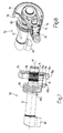
- FIG. 1 shows a parking brake 100 according to the invention.
- the parking brake 100 comprises a manual operating lever 10 which is pivoted on a fulcrum 11 and is located in a control cab (not illustrated) of a motor vehicle (not illustrated entirely either).
- the parking brake 100 has the purpose of braking a bevel pinion 12, which meshes with a fitted crown wheel 13, which transfers the motion to two axle shafts 14 (Figure 1 shows only one of them) on which are mounted two drive wheels W (only one shown in Figure 1) of the motor vehicle.
- a cable 17 (advantageously of a Bowden type) may be employed which is set between the lever 10 and the braking device 50. More in particular, the cable 17 ( Figure 1) is connected, on one side, to an eyelet 18 made on the lever 10, whilst, on the other side, it is connected to an eyelet 51 provided on a relay lever 52, which forms an integral part of the aforementioned braking device 50 (see further).
- the braking device 50 ( Figures 2 and 3) comprises a main body 53, which provides, as a single unit, a plate 53a for fixation to the frame (not shown) of the motor vehicle, a cylinder 53b, and projecting portions 53c, which are designed to support the brake disks 16 (visible only in Figure 1). Furthermore, the plate 53a comprises six through holes 54, each of which is provided with a respective bolt 55 for fixing to the rear transmission case (not illustrated) of the motor vehicle.
- the cylinder 53b is closed at its bottom end by a disk 56 fixed thereto with means known and not described.
- a chamber 57 designed to house a piston 58, on which an adjustment pin 59 rests.
- One end 59a of the adjustment pin 59 is in turn screwed to an internal threaded portion of a bushing 60 provided with a terminal flange 61.
- the bushing 60 is housed partially in a through hole 60a made in the disk 56 and can slide freely in said through hole 60a.
- a pack of Belleville washers 62 are tightly fitted; the washers 62 carrying out an indirect elastic action on the piston 58 via the bushing 60 and the adjustment pin 59 screwed thereto.
- a stem 64 Connected to the piston 58 on the other side of the adjustment pin 59 is a stem 64 terminating with a fork 65.
- the other end 59b of the adjustment pin 59 is threaded. Screwed to this end 59b is an adjustment detent 63a which is variably tightened for reasons that will be explained in greater detail hereinafter. As best shown in Figures 2 and 3, the aforesaid adjustment detent 63a is set between a nut 63 screwed onto the lower end of the adjustment pin 59 and the bottom surface of the disk 56.
- a portion 57a is designed to receive pressurized oil coming from a hydraulic circuit (not shown) of the motor vehicle. More particularly, with reference to Figures 2 and 3, it will be seen that the pressurized oil is brought to the portion 57a by means of a hydraulic line 66, inflow of oil being controlled by a solenoid valve 67 ( Figure 2). In addition, the oil contained in the portion 57a is discharged, when needed (see later), through a port 68, visible in Figure 3, connected directly to the rear-transmission case (not illustrated) of the tractor.
- the fork 65 connects the stem 64 via a pin 69 to a crank 70 provided with a circular cavity 71 ( Figure 2) coupled to a shaft 72 (see Figures 2 and 5).
- the coupling of the circular cavity 71 to the shaft 72 is such as to enable free rotation of the crank 70 with respect to the shaft 72.
- the crank 70 has a seat 73 designed to receive a pawl 74 for the purposes that will be described more fully hereinafter.
- the pawl 74 is idle with respect to its own seat 73.
- the shaft 72 is coupled to a cam 76 (Figure 8, and shown in greater detail in Figure 9) by means of splines 75 ( Figure 7).
- the cam 76 comprises a toothed seat 77 ( Figure 9) that is coupled to the splines 75 provided on the shaft 72 in such a way that said cam 76 is angularly fixed with respect to the shaft 72.
- two shaped cavities 78, 79 which have substantially the same shape and are obtained by removing part of the material constituting the periphery of the cam 76.
- the shaped cavity 79 has a length L much greater than the diameter D1 of the pawl 74 (see Figure 8). In fact, the pawl 74, in use, is located within the shaped cavity 79, as shown in Figure 9.
- the shaft 72 (see Figures 7 and 8), is in turn elastically stressed, via the grooves of the cam 76, by a spring 80 wound in a spiral about the longitudinal axis of symmetry (a) of the shaft 72.
- a first end 80a of the spring 80 rests on an abutment element unitary provided on the main body 53 (not shown), whilst a second end 80b is fixed to a small pin 81 fitted into a seat 81a ( Figure 9) made in the cam 76.
- the reasons for the presence of the spring 80 will be explained hereinafter.
- a shaped element 82 (see Figures 4-8), rotation of which, as will be seen more clearly hereinafter, packs together the brake disks 16 so as to brake the wheels W.
- the relay lever 52 at the end opposite to the one where the eyelet 51 is located, there is provided a circular seat (not visible in the annexed figures) engaged by the shaft 72. More particularly, the relay lever 52 can rotate freely with respect to the shaft 72. The cam 76 is thus located between the crank 70 and the relay lever 52, as shown in Figures 4 and 5.
- the relay lever 52 in turn has a pawl 83 (resting idle in its seat 83a in the lever 52), which, in use, is located within the shaped cavity 78.
- the pawl 83 has a diameter D2 ( Figure 5) smaller than the length L of the shaped cavity 78 so as to enable its free displacement within the shaped cavity 78.
- the first command can be imparted by the piston 58, which, to all effects, forms an integral part of a hydraulic actuator 84 comprising, moreover, the elements already described in relation to the cylinder 53b (see above).
- the second command can reach the cam 76 via the relay lever 52 operated manually by the operator using, for this purpose, the lever 10 (see Figure 1).
- each of the pawls 74 and 83 is located in an almost extreme upward position of its own shaped cavity 79 and 78, respectively.
- the pawl 83 will immediately contact the top portion 78a and will cause rotation of the cam 76 in the direction of the arrow F1.
- the pawl 74 will move upward and immediately contact the top portion 79a (on account of the pressure drop in the cylinder) and will set the cam 76 again in rotation in the direction of the arrow F1.
- both pawls 74 and 83 are in contact with the respective wall portions 79a and 78a and braking is thus ensured both by the hydraulic system and the mechanical system.
- the pawl 74 will release wall portion 79a and move in the direction of wall portion 79b.
- the cam 76 however will not rotate because it is prevented from doing so by pawl 83 still pressing against wall portion 78a. The brake therefore will remain on until the handbrake lever 10 also has been released.
- the bottom ends of the shaped cavities 78, 79 are slightly curved because said cavities 78, 79 are made with a ball-end two-fluted mill with a circular path.
- the path of the two pawls 83 and 74, respectively is circular, there consequently is no need for the bottom ends to be rectilinear, as long as the pawls 74 and 83 do not interfere with the slightly raised middle portion of the respective cavities 78 and 79 during their circular movement therethrough.
- a further function of the parking brake 100 is the park-lock function. Acting on the solenoid valve positioned in point 67, it is possible to discharge the pressurized oil present in the portion 57a through the port 68 obtaining the same result as in the case described previously. This is a particular function that is required from the motor vehicle with the engine running when the driver wants to be certain that the vehicle will remain still in particular conditions of manoeuvre without having to operate the lever 10 in the cab.
- the system for blocking the wheels W will be activated automatically whenever the engine of the motor vehicle is turned off or else when the signal to the control solenoid valve of the device is intentionally interrupted, whilst there will always be the possibility of engaging the hand brake manually both with the engine off and with the engine on.
- the same cam 76 provided with the two shaped cavities 78, 79 is used.
- the oil would be discharged by the portion 57a through the port 68, and the hand brake would remain engaged owing to the action of the actuator 84.
- the hand brake can be disengaged by resorting to an emergency device 85, which basically comprises the nut 63 and the adjustment detent 63a (see for example Figure 3). If the adjustment detent 63a is screwed on the threading provided on the end 59b until it presses against the bottom of the disk 56, the emergency pin 59 will be pulled down, allowing the other elements connected thereto to move downwards, including the cam 76, which will rotate in the direction of the arrow F2.
- an emergency device 85 basically comprises the nut 63 and the adjustment detent 63a (see for example Figure 3). If the adjustment detent 63a is screwed on the threading provided on the end 59b until it presses against the bottom of the disk 56, the emergency pin 59 will be pulled down, allowing the other elements connected thereto to move downwards, including the cam 76, which will rotate in the direction of the arrow F2.
- the advantages of the present parking brake are the following:
Landscapes
- Engineering & Computer Science (AREA)
- Transportation (AREA)
- Mechanical Engineering (AREA)
- Braking Arrangements (AREA)
- Regulating Braking Force (AREA)
- Braking Elements And Transmission Devices (AREA)
Applications Claiming Priority (2)
| Application Number | Priority Date | Filing Date | Title |
|---|---|---|---|
| ITBO20030533 | 2003-09-15 | ||
| IT000533A ITBO20030533A1 (it) | 2003-09-15 | 2003-09-15 | Freno di stazionamento per un autoveicolo, in particolare per un trattore |
Publications (3)
| Publication Number | Publication Date |
|---|---|
| EP1516791A2 true EP1516791A2 (de) | 2005-03-23 |
| EP1516791A3 EP1516791A3 (de) | 2005-12-07 |
| EP1516791B1 EP1516791B1 (de) | 2017-08-09 |
Family
ID=34179306
Family Applications (1)
| Application Number | Title | Priority Date | Filing Date |
|---|---|---|---|
| EP04104300.1A Expired - Lifetime EP1516791B1 (de) | 2003-09-15 | 2004-09-07 | Feststellbremse für ein Kraftfahrzeug, insbesondere Zugfahrzeug |
Country Status (3)
| Country | Link |
|---|---|
| US (1) | US7097260B2 (de) |
| EP (1) | EP1516791B1 (de) |
| IT (1) | ITBO20030533A1 (de) |
Cited By (3)
| Publication number | Priority date | Publication date | Assignee | Title |
|---|---|---|---|---|
| EP1914136A1 (de) * | 2006-10-16 | 2008-04-23 | CNH Italia S.p.A. | Feststellbremse mit Sicherheitsvorrichtung, im Besonderen für einen Ackerschlepper |
| WO2014060663A1 (fr) * | 2012-10-18 | 2014-04-24 | France Reducteurs | Ensemble de transmission pour engin automoteur, du type positionnable entre l'arbre primaire moteur et les roues dudit engin |
| US8849522B1 (en) * | 2012-12-12 | 2014-09-30 | Robert L. Mendenhall | Signal based safety system for construction zone |
Families Citing this family (1)
| Publication number | Priority date | Publication date | Assignee | Title |
|---|---|---|---|---|
| GB0518133D0 (en) * | 2005-09-06 | 2005-10-12 | Haldex Brake Products Ltd | Braking system |
Citations (2)
| Publication number | Priority date | Publication date | Assignee | Title |
|---|---|---|---|---|
| DE3015029A1 (de) | 1979-04-19 | 1980-10-30 | Kubota Ltd | Traktorgetriebe |
| WO2002020324A1 (en) | 2000-09-05 | 2002-03-14 | Fico Cables, S.A. | Electrically powered parking brake |
Family Cites Families (12)
| Publication number | Priority date | Publication date | Assignee | Title |
|---|---|---|---|---|
| JPS4917163B1 (de) * | 1970-01-17 | 1974-04-27 | ||
| DE2510193A1 (de) * | 1975-03-08 | 1976-09-16 | Wabco Westinghouse Gmbh | Druckmittelbetaetigte scheibenbremse, insbesondere fuer kraftfahrzeuge |
| US4273388A (en) * | 1979-07-13 | 1981-06-16 | Zdenek Muller | Air brake safety mechanism |
| JPS58207571A (ja) * | 1982-05-28 | 1983-12-03 | Aisin Warner Ltd | 自動変速機パ−キング機構 |
| JPS59184049A (ja) * | 1983-03-31 | 1984-10-19 | Aisin Seiki Co Ltd | 変速機のパ−キング機構 |
| US4746171A (en) * | 1986-11-19 | 1988-05-24 | General Signal Corporation | Parking brake system for railway vehicles |
| US5131288A (en) * | 1989-12-11 | 1992-07-21 | Dura Mechanical Components, Inc. | Remote actuator for parking brake control assembly |
| US5309786A (en) * | 1993-03-08 | 1994-05-10 | Dura Mechanical Components, Inc. | Self-adjusting parking brake actuator |
| US6126246A (en) * | 1996-09-13 | 2000-10-03 | Decker, Sr.; Dan | Towed vehicle braking system |
| US6105459A (en) * | 1998-12-14 | 2000-08-22 | Ford Motor Company | Cable lock and release apparatus |
| ITBO20000449A1 (it) * | 2000-07-21 | 2002-01-21 | New Holland Italia Spa | Veicolo . |
| DE10163043A1 (de) * | 2001-12-21 | 2003-07-03 | Daimler Chrysler Ag | Feststellbremsvorrichtung für Fahrzeuge, sowie Montageverfahren hierzu |
-
2003
- 2003-09-15 IT IT000533A patent/ITBO20030533A1/it unknown
-
2004
- 2004-09-07 EP EP04104300.1A patent/EP1516791B1/de not_active Expired - Lifetime
- 2004-09-13 US US10/939,808 patent/US7097260B2/en not_active Expired - Lifetime
Patent Citations (2)
| Publication number | Priority date | Publication date | Assignee | Title |
|---|---|---|---|---|
| DE3015029A1 (de) | 1979-04-19 | 1980-10-30 | Kubota Ltd | Traktorgetriebe |
| WO2002020324A1 (en) | 2000-09-05 | 2002-03-14 | Fico Cables, S.A. | Electrically powered parking brake |
Cited By (5)
| Publication number | Priority date | Publication date | Assignee | Title |
|---|---|---|---|---|
| EP1914136A1 (de) * | 2006-10-16 | 2008-04-23 | CNH Italia S.p.A. | Feststellbremse mit Sicherheitsvorrichtung, im Besonderen für einen Ackerschlepper |
| WO2014060663A1 (fr) * | 2012-10-18 | 2014-04-24 | France Reducteurs | Ensemble de transmission pour engin automoteur, du type positionnable entre l'arbre primaire moteur et les roues dudit engin |
| FR2997054A1 (fr) * | 2012-10-18 | 2014-04-25 | France Reducteurs | Ensemble de transmission pour engin automoteur, du type positionnable entre l'arbre primaire moteur et les roues dudit engin |
| US9885416B2 (en) | 2012-10-18 | 2018-02-06 | France Reducteurs | Transmission assembly for a self-propelled machine, of the type that can be positioned between the primary motor shaft and the wheels of said machine |
| US8849522B1 (en) * | 2012-12-12 | 2014-09-30 | Robert L. Mendenhall | Signal based safety system for construction zone |
Also Published As
| Publication number | Publication date |
|---|---|
| US20050077781A1 (en) | 2005-04-14 |
| EP1516791B1 (de) | 2017-08-09 |
| EP1516791A3 (de) | 2005-12-07 |
| US7097260B2 (en) | 2006-08-29 |
| ITBO20030533A1 (it) | 2005-03-16 |
Similar Documents
| Publication | Publication Date | Title |
|---|---|---|
| US6581738B2 (en) | Parking lock for a motor vehicle with an emergency release device | |
| US4572340A (en) | Safety lock vehicle transmission | |
| US5203616A (en) | Electrohydraulic parking brake control system | |
| US7490528B2 (en) | Park inhibit assembly for an electric transmission range selection system | |
| CA2164894C (en) | Drag brake for truck mounted, clutch operated power takeoff device | |
| US4462487A (en) | Combined vehicle service and parking brake control mechanism | |
| US6527096B2 (en) | Control device for the parking lock of a motor vehicle | |
| EP0522761B1 (de) | In einer Flüssigkeit untergetauchte Scheibenbremse | |
| AU2019205012A1 (en) | Park brake and traction drive bypass interlock | |
| US20060278029A1 (en) | Driving gear selector device for an automatic transmission of a motor vehicle | |
| MXPA04002308A (es) | Dispositivo de toma de fuerza. | |
| US7931343B2 (en) | Parking brake with safety device | |
| US4069900A (en) | Combination transmission neutralizer and power train interlock system | |
| EP1516791B1 (de) | Feststellbremse für ein Kraftfahrzeug, insbesondere Zugfahrzeug | |
| US5323890A (en) | Transmission assembly for working vehicles | |
| US5101945A (en) | (Clutch-brake pedal) brake system | |
| CA2424153A1 (en) | Selector system for vehicle | |
| US4915131A (en) | Hill-holder | |
| US3967709A (en) | Interlock system for parking brake and transmission control | |
| US8763749B2 (en) | Operating mechanism for cruise control and motion control in an off-road vehicle operating on hydrostatic transmission | |
| JPH1191386A (ja) | 作業車 | |
| US4299300A (en) | Vehicle steering brake and clutch control | |
| US4042084A (en) | Vehicle clutch control assembly | |
| JPH02179573A (ja) | 自動変速機のパーキング機構 | |
| JPH0516056Y2 (de) |
Legal Events
| Date | Code | Title | Description |
|---|---|---|---|
| PUAI | Public reference made under article 153(3) epc to a published international application that has entered the european phase |
Free format text: ORIGINAL CODE: 0009012 |
|
| AK | Designated contracting states |
Kind code of ref document: A2 Designated state(s): AT BE BG CH CY CZ DE DK EE ES FI FR GB GR HU IE IT LI LU MC NL PL PT RO SE SI SK TR |
|
| AX | Request for extension of the european patent |
Extension state: AL HR LT LV MK |
|
| PUAL | Search report despatched |
Free format text: ORIGINAL CODE: 0009013 |
|
| AK | Designated contracting states |
Kind code of ref document: A3 Designated state(s): AT BE BG CH CY CZ DE DK EE ES FI FR GB GR HU IE IT LI LU MC NL PL PT RO SE SI SK TR |
|
| AX | Request for extension of the european patent |
Extension state: AL HR LT LV MK |
|
| RIC1 | Information provided on ipc code assigned before grant |
Ipc: 7B 60T 7/12 A Ipc: 7B 60T 1/06 B Ipc: 7B 60T 11/04 B |
|
| 17P | Request for examination filed |
Effective date: 20060522 |
|
| AKX | Designation fees paid |
Designated state(s): AT BE BG CH CY CZ DE DK EE ES FI FR GB GR HU IE IT LI LU MC NL PL PT RO SE SI SK TR |
|
| 17Q | First examination report despatched |
Effective date: 20081205 |
|
| RAP1 | Party data changed (applicant data changed or rights of an application transferred) |
Owner name: CNH ITALIA S.P.A. |
|
| RAP1 | Party data changed (applicant data changed or rights of an application transferred) |
Owner name: CNH ITALIA S.P.A. |
|
| RAP1 | Party data changed (applicant data changed or rights of an application transferred) |
Owner name: CNH INDUSTRIAL ITALIA S.P.A. |
|
| GRAP | Despatch of communication of intention to grant a patent |
Free format text: ORIGINAL CODE: EPIDOSNIGR1 |
|
| INTG | Intention to grant announced |
Effective date: 20170321 |
|
| GRAS | Grant fee paid |
Free format text: ORIGINAL CODE: EPIDOSNIGR3 |
|
| GRAJ | Information related to disapproval of communication of intention to grant by the applicant or resumption of examination proceedings by the epo deleted |
Free format text: ORIGINAL CODE: EPIDOSDIGR1 |
|
| GRAL | Information related to payment of fee for publishing/printing deleted |
Free format text: ORIGINAL CODE: EPIDOSDIGR3 |
|
| GRAR | Information related to intention to grant a patent recorded |
Free format text: ORIGINAL CODE: EPIDOSNIGR71 |
|
| GRAA | (expected) grant |
Free format text: ORIGINAL CODE: 0009210 |
|
| INTC | Intention to grant announced (deleted) | ||
| AK | Designated contracting states |
Kind code of ref document: B1 Designated state(s): AT BE BG CH CY CZ DE DK EE ES FI FR GB GR HU IE IT LI LU MC NL PL PT RO SE SI SK TR |
|
| INTG | Intention to grant announced |
Effective date: 20170704 |
|
| REG | Reference to a national code |
Ref country code: GB Ref legal event code: FG4D |
|
| REG | Reference to a national code |
Ref country code: CH Ref legal event code: EP Ref country code: AT Ref legal event code: REF Ref document number: 916442 Country of ref document: AT Kind code of ref document: T Effective date: 20170815 |
|
| REG | Reference to a national code |
Ref country code: IE Ref legal event code: FG4D |
|
| REG | Reference to a national code |
Ref country code: FR Ref legal event code: PLFP Year of fee payment: 14 |
|
| REG | Reference to a national code |
Ref country code: DE Ref legal event code: R096 Ref document number: 602004051633 Country of ref document: DE |
|
| REG | Reference to a national code |
Ref country code: DE Ref legal event code: R084 Ref document number: 602004051633 Country of ref document: DE |
|
| REG | Reference to a national code |
Ref country code: GB Ref legal event code: 746 Effective date: 20171113 |
|
| REG | Reference to a national code |
Ref country code: NL Ref legal event code: MP Effective date: 20170809 |
|
| REG | Reference to a national code |
Ref country code: AT Ref legal event code: MK05 Ref document number: 916442 Country of ref document: AT Kind code of ref document: T Effective date: 20170809 |
|
| PG25 | Lapsed in a contracting state [announced via postgrant information from national office to epo] |
Ref country code: SE Free format text: LAPSE BECAUSE OF FAILURE TO SUBMIT A TRANSLATION OF THE DESCRIPTION OR TO PAY THE FEE WITHIN THE PRESCRIBED TIME-LIMIT Effective date: 20170809 Ref country code: NL Free format text: LAPSE BECAUSE OF FAILURE TO SUBMIT A TRANSLATION OF THE DESCRIPTION OR TO PAY THE FEE WITHIN THE PRESCRIBED TIME-LIMIT Effective date: 20170809 Ref country code: FI Free format text: LAPSE BECAUSE OF FAILURE TO SUBMIT A TRANSLATION OF THE DESCRIPTION OR TO PAY THE FEE WITHIN THE PRESCRIBED TIME-LIMIT Effective date: 20170809 Ref country code: AT Free format text: LAPSE BECAUSE OF FAILURE TO SUBMIT A TRANSLATION OF THE DESCRIPTION OR TO PAY THE FEE WITHIN THE PRESCRIBED TIME-LIMIT Effective date: 20170809 |
|
| PG25 | Lapsed in a contracting state [announced via postgrant information from national office to epo] |
Ref country code: GR Free format text: LAPSE BECAUSE OF FAILURE TO SUBMIT A TRANSLATION OF THE DESCRIPTION OR TO PAY THE FEE WITHIN THE PRESCRIBED TIME-LIMIT Effective date: 20171110 Ref country code: ES Free format text: LAPSE BECAUSE OF FAILURE TO SUBMIT A TRANSLATION OF THE DESCRIPTION OR TO PAY THE FEE WITHIN THE PRESCRIBED TIME-LIMIT Effective date: 20170809 Ref country code: BG Free format text: LAPSE BECAUSE OF FAILURE TO SUBMIT A TRANSLATION OF THE DESCRIPTION OR TO PAY THE FEE WITHIN THE PRESCRIBED TIME-LIMIT Effective date: 20171109 Ref country code: PL Free format text: LAPSE BECAUSE OF FAILURE TO SUBMIT A TRANSLATION OF THE DESCRIPTION OR TO PAY THE FEE WITHIN THE PRESCRIBED TIME-LIMIT Effective date: 20170809 |
|
| PG25 | Lapsed in a contracting state [announced via postgrant information from national office to epo] |
Ref country code: RO Free format text: LAPSE BECAUSE OF FAILURE TO SUBMIT A TRANSLATION OF THE DESCRIPTION OR TO PAY THE FEE WITHIN THE PRESCRIBED TIME-LIMIT Effective date: 20170809 Ref country code: DK Free format text: LAPSE BECAUSE OF FAILURE TO SUBMIT A TRANSLATION OF THE DESCRIPTION OR TO PAY THE FEE WITHIN THE PRESCRIBED TIME-LIMIT Effective date: 20170809 Ref country code: CZ Free format text: LAPSE BECAUSE OF FAILURE TO SUBMIT A TRANSLATION OF THE DESCRIPTION OR TO PAY THE FEE WITHIN THE PRESCRIBED TIME-LIMIT Effective date: 20170809 |
|
| REG | Reference to a national code |
Ref country code: CH Ref legal event code: PL |
|
| REG | Reference to a national code |
Ref country code: DE Ref legal event code: R097 Ref document number: 602004051633 Country of ref document: DE |
|
| PG25 | Lapsed in a contracting state [announced via postgrant information from national office to epo] |
Ref country code: MC Free format text: LAPSE BECAUSE OF FAILURE TO SUBMIT A TRANSLATION OF THE DESCRIPTION OR TO PAY THE FEE WITHIN THE PRESCRIBED TIME-LIMIT Effective date: 20170809 Ref country code: EE Free format text: LAPSE BECAUSE OF FAILURE TO SUBMIT A TRANSLATION OF THE DESCRIPTION OR TO PAY THE FEE WITHIN THE PRESCRIBED TIME-LIMIT Effective date: 20170809 Ref country code: SK Free format text: LAPSE BECAUSE OF FAILURE TO SUBMIT A TRANSLATION OF THE DESCRIPTION OR TO PAY THE FEE WITHIN THE PRESCRIBED TIME-LIMIT Effective date: 20170809 |
|
| PLBE | No opposition filed within time limit |
Free format text: ORIGINAL CODE: 0009261 |
|
| STAA | Information on the status of an ep patent application or granted ep patent |
Free format text: STATUS: NO OPPOSITION FILED WITHIN TIME LIMIT |
|
| REG | Reference to a national code |
Ref country code: IE Ref legal event code: MM4A |
|
| REG | Reference to a national code |
Ref country code: BE Ref legal event code: MM Effective date: 20170930 |
|
| PG25 | Lapsed in a contracting state [announced via postgrant information from national office to epo] |
Ref country code: LU Free format text: LAPSE BECAUSE OF NON-PAYMENT OF DUE FEES Effective date: 20170907 |
|
| 26N | No opposition filed |
Effective date: 20180511 |
|
| REG | Reference to a national code |
Ref country code: FR Ref legal event code: PLFP Year of fee payment: 15 |
|
| PG25 | Lapsed in a contracting state [announced via postgrant information from national office to epo] |
Ref country code: LI Free format text: LAPSE BECAUSE OF NON-PAYMENT OF DUE FEES Effective date: 20170930 Ref country code: CH Free format text: LAPSE BECAUSE OF NON-PAYMENT OF DUE FEES Effective date: 20170930 Ref country code: IE Free format text: LAPSE BECAUSE OF NON-PAYMENT OF DUE FEES Effective date: 20170907 |
|
| PG25 | Lapsed in a contracting state [announced via postgrant information from national office to epo] |
Ref country code: BE Free format text: LAPSE BECAUSE OF NON-PAYMENT OF DUE FEES Effective date: 20170930 Ref country code: SI Free format text: LAPSE BECAUSE OF FAILURE TO SUBMIT A TRANSLATION OF THE DESCRIPTION OR TO PAY THE FEE WITHIN THE PRESCRIBED TIME-LIMIT Effective date: 20170809 |
|
| PG25 | Lapsed in a contracting state [announced via postgrant information from national office to epo] |
Ref country code: HU Free format text: LAPSE BECAUSE OF FAILURE TO SUBMIT A TRANSLATION OF THE DESCRIPTION OR TO PAY THE FEE WITHIN THE PRESCRIBED TIME-LIMIT; INVALID AB INITIO Effective date: 20040907 |
|
| PG25 | Lapsed in a contracting state [announced via postgrant information from national office to epo] |
Ref country code: CY Free format text: LAPSE BECAUSE OF NON-PAYMENT OF DUE FEES Effective date: 20170809 |
|
| PGFP | Annual fee paid to national office [announced via postgrant information from national office to epo] |
Ref country code: GB Payment date: 20190926 Year of fee payment: 16 |
|
| PG25 | Lapsed in a contracting state [announced via postgrant information from national office to epo] |
Ref country code: TR Free format text: LAPSE BECAUSE OF FAILURE TO SUBMIT A TRANSLATION OF THE DESCRIPTION OR TO PAY THE FEE WITHIN THE PRESCRIBED TIME-LIMIT Effective date: 20170809 |
|
| PG25 | Lapsed in a contracting state [announced via postgrant information from national office to epo] |
Ref country code: PT Free format text: LAPSE BECAUSE OF FAILURE TO SUBMIT A TRANSLATION OF THE DESCRIPTION OR TO PAY THE FEE WITHIN THE PRESCRIBED TIME-LIMIT Effective date: 20170809 |
|
| GBPC | Gb: european patent ceased through non-payment of renewal fee |
Effective date: 20200907 |
|
| PG25 | Lapsed in a contracting state [announced via postgrant information from national office to epo] |
Ref country code: GB Free format text: LAPSE BECAUSE OF NON-PAYMENT OF DUE FEES Effective date: 20200907 |
|
| PGFP | Annual fee paid to national office [announced via postgrant information from national office to epo] |
Ref country code: DE Payment date: 20220928 Year of fee payment: 19 |
|
| PGFP | Annual fee paid to national office [announced via postgrant information from national office to epo] |
Ref country code: FR Payment date: 20220924 Year of fee payment: 19 |
|
| PGFP | Annual fee paid to national office [announced via postgrant information from national office to epo] |
Ref country code: IT Payment date: 20220913 Year of fee payment: 19 |
|
| REG | Reference to a national code |
Ref country code: DE Ref legal event code: R119 Ref document number: 602004051633 Country of ref document: DE |
|
| PG25 | Lapsed in a contracting state [announced via postgrant information from national office to epo] |
Ref country code: FR Free format text: LAPSE BECAUSE OF NON-PAYMENT OF DUE FEES Effective date: 20230930 Ref country code: DE Free format text: LAPSE BECAUSE OF NON-PAYMENT OF DUE FEES Effective date: 20240403 |
|
| PG25 | Lapsed in a contracting state [announced via postgrant information from national office to epo] |
Ref country code: IT Free format text: LAPSE BECAUSE OF NON-PAYMENT OF DUE FEES Effective date: 20230907 |
|
| PG25 | Lapsed in a contracting state [announced via postgrant information from national office to epo] |
Ref country code: IT Free format text: LAPSE BECAUSE OF NON-PAYMENT OF DUE FEES Effective date: 20230907 |