EP1516712A2 - Method of inflation extrusion molding, extrusion molding apparatus therefor, and process for producing pressure-sensitive adhesive sheet - Google Patents
Method of inflation extrusion molding, extrusion molding apparatus therefor, and process for producing pressure-sensitive adhesive sheet Download PDFInfo
- Publication number
- EP1516712A2 EP1516712A2 EP04022191A EP04022191A EP1516712A2 EP 1516712 A2 EP1516712 A2 EP 1516712A2 EP 04022191 A EP04022191 A EP 04022191A EP 04022191 A EP04022191 A EP 04022191A EP 1516712 A2 EP1516712 A2 EP 1516712A2
- Authority
- EP
- European Patent Office
- Prior art keywords
- resin material
- sensitive adhesive
- roller members
- cylindrical
- flat tube
- Prior art date
- Legal status (The legal status is an assumption and is not a legal conclusion. Google has not performed a legal analysis and makes no representation as to the accuracy of the status listed.)
- Granted
Links
Images


Classifications
-
- B—PERFORMING OPERATIONS; TRANSPORTING
- B29—WORKING OF PLASTICS; WORKING OF SUBSTANCES IN A PLASTIC STATE IN GENERAL
- B29C—SHAPING OR JOINING OF PLASTICS; SHAPING OF MATERIAL IN A PLASTIC STATE, NOT OTHERWISE PROVIDED FOR; AFTER-TREATMENT OF THE SHAPED PRODUCTS, e.g. REPAIRING
- B29C55/00—Shaping by stretching, e.g. drawing through a die; Apparatus therefor
- B29C55/28—Shaping by stretching, e.g. drawing through a die; Apparatus therefor of blown tubular films, e.g. by inflation
-
- B—PERFORMING OPERATIONS; TRANSPORTING
- B29—WORKING OF PLASTICS; WORKING OF SUBSTANCES IN A PLASTIC STATE IN GENERAL
- B29C—SHAPING OR JOINING OF PLASTICS; SHAPING OF MATERIAL IN A PLASTIC STATE, NOT OTHERWISE PROVIDED FOR; AFTER-TREATMENT OF THE SHAPED PRODUCTS, e.g. REPAIRING
- B29C48/00—Extrusion moulding, i.e. expressing the moulding material through a die or nozzle which imparts the desired form; Apparatus therefor
- B29C48/25—Component parts, details or accessories; Auxiliary operations
- B29C48/88—Thermal treatment of the stream of extruded material, e.g. cooling
- B29C48/90—Thermal treatment of the stream of extruded material, e.g. cooling with calibration or sizing, i.e. combined with fixing or setting of the final dimensions of the extruded article
- B29C48/901—Thermal treatment of the stream of extruded material, e.g. cooling with calibration or sizing, i.e. combined with fixing or setting of the final dimensions of the extruded article of hollow bodies
- B29C48/903—Thermal treatment of the stream of extruded material, e.g. cooling with calibration or sizing, i.e. combined with fixing or setting of the final dimensions of the extruded article of hollow bodies externally
-
- B—PERFORMING OPERATIONS; TRANSPORTING
- B29—WORKING OF PLASTICS; WORKING OF SUBSTANCES IN A PLASTIC STATE IN GENERAL
- B29C—SHAPING OR JOINING OF PLASTICS; SHAPING OF MATERIAL IN A PLASTIC STATE, NOT OTHERWISE PROVIDED FOR; AFTER-TREATMENT OF THE SHAPED PRODUCTS, e.g. REPAIRING
- B29C48/00—Extrusion moulding, i.e. expressing the moulding material through a die or nozzle which imparts the desired form; Apparatus therefor
- B29C48/03—Extrusion moulding, i.e. expressing the moulding material through a die or nozzle which imparts the desired form; Apparatus therefor characterised by the shape of the extruded material at extrusion
- B29C48/07—Flat, e.g. panels
- B29C48/08—Flat, e.g. panels flexible, e.g. films
-
- B—PERFORMING OPERATIONS; TRANSPORTING
- B29—WORKING OF PLASTICS; WORKING OF SUBSTANCES IN A PLASTIC STATE IN GENERAL
- B29C—SHAPING OR JOINING OF PLASTICS; SHAPING OF MATERIAL IN A PLASTIC STATE, NOT OTHERWISE PROVIDED FOR; AFTER-TREATMENT OF THE SHAPED PRODUCTS, e.g. REPAIRING
- B29C48/00—Extrusion moulding, i.e. expressing the moulding material through a die or nozzle which imparts the desired form; Apparatus therefor
- B29C48/03—Extrusion moulding, i.e. expressing the moulding material through a die or nozzle which imparts the desired form; Apparatus therefor characterised by the shape of the extruded material at extrusion
- B29C48/09—Articles with cross-sections having partially or fully enclosed cavities, e.g. pipes or channels
- B29C48/10—Articles with cross-sections having partially or fully enclosed cavities, e.g. pipes or channels flexible, e.g. blown foils
-
- B—PERFORMING OPERATIONS; TRANSPORTING
- B29—WORKING OF PLASTICS; WORKING OF SUBSTANCES IN A PLASTIC STATE IN GENERAL
- B29C—SHAPING OR JOINING OF PLASTICS; SHAPING OF MATERIAL IN A PLASTIC STATE, NOT OTHERWISE PROVIDED FOR; AFTER-TREATMENT OF THE SHAPED PRODUCTS, e.g. REPAIRING
- B29C48/00—Extrusion moulding, i.e. expressing the moulding material through a die or nozzle which imparts the desired form; Apparatus therefor
- B29C48/25—Component parts, details or accessories; Auxiliary operations
- B29C48/30—Extrusion nozzles or dies
-
- B—PERFORMING OPERATIONS; TRANSPORTING
- B29—WORKING OF PLASTICS; WORKING OF SUBSTANCES IN A PLASTIC STATE IN GENERAL
- B29C—SHAPING OR JOINING OF PLASTICS; SHAPING OF MATERIAL IN A PLASTIC STATE, NOT OTHERWISE PROVIDED FOR; AFTER-TREATMENT OF THE SHAPED PRODUCTS, e.g. REPAIRING
- B29C48/00—Extrusion moulding, i.e. expressing the moulding material through a die or nozzle which imparts the desired form; Apparatus therefor
- B29C48/25—Component parts, details or accessories; Auxiliary operations
- B29C48/88—Thermal treatment of the stream of extruded material, e.g. cooling
- B29C48/90—Thermal treatment of the stream of extruded material, e.g. cooling with calibration or sizing, i.e. combined with fixing or setting of the final dimensions of the extruded article
- B29C48/901—Thermal treatment of the stream of extruded material, e.g. cooling with calibration or sizing, i.e. combined with fixing or setting of the final dimensions of the extruded article of hollow bodies
-
- B—PERFORMING OPERATIONS; TRANSPORTING
- B29—WORKING OF PLASTICS; WORKING OF SUBSTANCES IN A PLASTIC STATE IN GENERAL
- B29C—SHAPING OR JOINING OF PLASTICS; SHAPING OF MATERIAL IN A PLASTIC STATE, NOT OTHERWISE PROVIDED FOR; AFTER-TREATMENT OF THE SHAPED PRODUCTS, e.g. REPAIRING
- B29C48/00—Extrusion moulding, i.e. expressing the moulding material through a die or nozzle which imparts the desired form; Apparatus therefor
- B29C48/001—Combinations of extrusion moulding with other shaping operations
- B29C48/0018—Combinations of extrusion moulding with other shaping operations combined with shaping by orienting, stretching or shrinking, e.g. film blowing
-
- B—PERFORMING OPERATIONS; TRANSPORTING
- B29—WORKING OF PLASTICS; WORKING OF SUBSTANCES IN A PLASTIC STATE IN GENERAL
- B29C—SHAPING OR JOINING OF PLASTICS; SHAPING OF MATERIAL IN A PLASTIC STATE, NOT OTHERWISE PROVIDED FOR; AFTER-TREATMENT OF THE SHAPED PRODUCTS, e.g. REPAIRING
- B29C48/00—Extrusion moulding, i.e. expressing the moulding material through a die or nozzle which imparts the desired form; Apparatus therefor
- B29C48/001—Combinations of extrusion moulding with other shaping operations
- B29C48/0019—Combinations of extrusion moulding with other shaping operations combined with shaping by flattening, folding or bending
Definitions
- the present invention relates to a method of the inflation extrusion molding of a single- or multilayered film or sheet, an apparatus for the molding, and to a process for producing a pressure-sensitive adhesive sheet with these.
- Patent Document 1 JP 50-020578 B
- the direction of rotation of the guide rollers do not coincide with the direction of resin material spreading when the resin material which has been inflated into a cylindrical shape by blown-film extrusion is folded so as to have an elliptic section. Because of this, even when the surfaces of the guide rollers have been coated with Teflon or the like, the resin material shakes undesirably and is not smoothly spread into a flat tube shape having an elliptic section, resulting in the occasional occurrence of folding wrinkles.
- an object of the invention is to provide a method of inflation extrusion molding by which a resin material, e.g., a pressure-sensitive adhesive sheet, extruded by blown-film extrusion can be easily deformed into a flat tube shape having an elongated elliptic section and can be inhibited from developing wrinkles or the like upon folding.
- a resin material e.g., a pressure-sensitive adhesive sheet
- Another object of the invention is to provide an extrusion molding apparatus for use in the method.
- the invention has been achieved in order to overcome the problems described above.
- the invention provides a method of inflation extrusion molding, comprising:
- the guide device serves to reduce the force which restrains the resin material from deforming into a flat tube shape having an elongated elliptic section.
- the film or sheet which has passed through the space between the stabilizers is hence inhibited from occasionally generating wrinkles upon folding, and a high-quality film or sheet having a predetermined width can be stably produced.
- the stabilizers comprise roller members arranged in rows and the roller members each are arranged so that the direction of rotation thereof is substantially the same as the direction in which the resin material is spread when deformed into a flat tube shape having an elongated elliptic section, to thereby serve as the guide device.
- the stabilizers are constituted by roller members arranged in rows, the frictional resistance in the direction in which the extruded resin advances is reduced. Furthermore, since the roller members each are arranged so that the direction of rotation thereof is substantially the same as the direction in which the resin material is spread when deformed into a flat tube shape having an elongated elliptic section, the deformation to a flat tube shape having an elongated elliptic section can be conducted more easily. Consequently, the occurrence of wrinkles during folding can be inhibited with higher certainty.
- the roller members each preferably comprise a plurality of rollers arranged in a row.
- roller members constituting the stabilizers each comprise a plurality of short rollers arranged in a row, the regions where these roller members come into contact with a resin material do not have a large area and, hence, the resistance of friction between the roller members and the resin material can be reduced.
- the invention further provides an apparatus for inflation extrusion molding, comprising:
- the guide device serves to reduce the force which restrains the resin material from deforming into a flat tube shape having an elongated elliptic section.
- the film or sheet which has passed through the space between the stabilizers is hence inhibited from occasionally generating wrinkles upon folding, and a high-quality film or sheet having a predetermined width can be stably produced.
- the stabilizers are constituted by roller members arranged in rows, the frictional resistance in the direction in which the extruded resin advances is reduced.
- roller members each are arranged so that the direction of rotation thereof is substantially the same as the direction in which the resin material is spread when deformed into a flat tube shape having an elongated elliptic section, the deformation to a flat tube shape having an elongated elliptic section can be conducted more easily. Consequently, the occurrence of wrinkles during folding can be inhibited with higher certainty.
- the roller members arranged in rows are preferably arranged so as to give a gap between adjacent roller members of not larger than the diameter of each roller member.
- roller members are arranged so as to give a gap between adjacent roller members of not larger than the diameter of each roller member, the resin material can be prevented from coming into the space between adjacent roller members.
- the film or sheet thus produced can hence be inhibited from developing surface wrinkles.
- the roller members each preferably comprise a plurality of rollers arranged in a row.
- roller members constituting the stabilizers each comprise a plurality of short rollers arranged in a row, the regions where these roller members come into contact with a resin material do not have a large area and, hence, the resistance of friction between the roller members and the resin material can be reduced.
- the invention furthermore provides a process for producing a pressure-sensitive adhesive sheet, comprising:
- the guide device serves to reduce the force which restrains the resin materials for forming a pressure-sensitive adhesive layer and a substrate from deforming into a flat tube shape having an elongated elliptic section.
- the pressure-sensitive adhesive sheet which has passed through the space between the stabilizers is hence inhibited from occasionally generating wrinkles upon folding.
- a high-quality pressure-sensitive adhesive sheet having a predetermined width can be stably produced.
- the stabilizers comprise roller members arranged in rows and the roller members each are arranged so that the direction of rotation thereof is substantially the same as the direction in which the resin material is spread when deformed into a flat tube shape having an elongated elliptic section, to thereby serve as the guide device.
- the stabilizers are constituted by roller members arranged in rows, the frictional resistance in the direction in which the extruded resin advances is reduced. Furthermore, since the roller members each are arranged so that the direction of rotation thereof is substantially the same as the direction in which the resin material is spread when deformed into a flat tube shape having an elongated elliptic section, the deformation to a flat tube shape having an elongated elliptic section can be conducted more easily. Consequently, the occurrence of wrinkles during folding in the formation of a pressure-sensitive adhesive sheet can be inhibited with higher certainty even when the pressure-sensitive adhesive layer comes into contact with the stabilizers.
- the roller members each preferably comprise a plurality of rollers arranged in a row.
- roller members constituting the stabilizers each comprise a plurality of short rollers arranged in a row, the regions where these roller members come into contact with a resin material do not have a large area and, hence, the resistance of friction between the roller members and the resin material can be reduced. Because of this, even a pressure-sensitive adhesive sheet, which includes a pressure-sensitive adhesive layer, can be easily and stably formed in a wrinkle-free state.
- the invention which has the constitutions described above, brings about the following effects.
- stabilizers are used for sandwiching and pressing the cylindrical inflated resin material and deforming it into a flat tube shape having an elongated elliptic section.
- the stabilizers are constituted by roller members arranged in rows and these roller members each are constituted by a plurality of short rollers rotating in a direction substantially the same as the direction in which the resin material expands and spreads.
- the frictional resistance of contact with the rollers which restrains the resin material from spreading into a flat tube shape having an elongated elliptic section, is reduced and the resin material can be easily deformed into a flat tube shape having an elongated elliptic section. Because of this, the method of inflation extrusion molding can inhibit generation of wrinkles even in the extrusion molding of a pressure-sensitive adhesive sheet having a pressure-sensitive adhesive layer on one side, not to mention in the inflation extrusion molding of various resin materials.
- Fig. 1 is a diagrammatic view illustrating an embodiment of the method of inflation extrusion molding.
- numeral 1 denotes a die into which one or more resin materials extruded from one or more extruders not shown are introduced.
- the die 1 has, formed therein, one or more passages for the resin material(s) to be introduced from one or more extruders, although the passages are not shown.
- the die has concentrically arranged ejection openings through which the resin materials introduced into the die are ejected.
- a resin material for forming a pressure-sensitive adhesive layer and a resin material for forming a substrate are introduced into the respective passages so that the former and latter resin materials will constitute an outer layer and an inner layer, respectively.
- the disposition of the substrate-forming resin material so as to constitute an inner layer is intended to locate the substrate part inside when the flat tube shape having an elongated elliptic section is folded, as will be described later.
- numeral 2 denotes a resin material which has been extruded and ejected from the die 1 through an ejection opening and inflated into a cylindrical shape having a predetermined diameter.
- Symbols 3a, 3b, 4a, and 4b denote regulating members by which the resin material ejected from the die 1 is positioned so as not to shift back, forth, right, or left. Due to these regulating members 3a, 3b, 4a, and 4b, the cylindrical inflated resin material can continuously move upward without undergoing such horizontal shifting.
- Symbols 5a and 5b denote stabilizers which are disposed symmetrically about a vertical plane so as to face each other at a predetermined angle and which serve to deform the cylindrical inflated resin material 2 into a flat tube shape having an elongated elliptic section.
- Symbols 6a and 6b denote pinch rollers by which the resin material which has passed through the space between the stabilizers 5a and 5b and folded is sent to a take-up roller or the like not shown.
- the angle of aperture ⁇ between the stabilizers 5a and 5b preferably is appropriately selected according to the viscosity of the resin material 2, and it is necessary for the selection to take account of the gradient at which the cylindrical inflated resin material 2 is deformed between the stabilizers 5a and 5b, the area of contact with the stabilizers 5a and 5b, etc. It is preferred that the angle of aperture ⁇ be regulated to a value in the range of 10° to 45°, preferably 10° to 30°, more preferably 10° to 25°.
- the stabilizers 5a and 5b have been disposed so as to face each other at a predetermined angle so that the passage of the resin material which has been ejected from the die 1 and inflated into a cylindrical shape is narrowed along the direction of forward movement of the resin material and that the cylindrical inflated resin material can be thus deformed into a flat tube shape having an elongated elliptic section.
- These stabilizers 5a and 5b are constituted by roller members 7 arranged in rows. These roller members 7 are arranged with an appropriate pitch H so as to give a gap h between adjacent roller members of not larger than the diameter of each roller member 7.
- the resin material 2 which is moving forward while being in contact with these roller members 7 does not come into the space between adjacent roller members 7 during the movement. As a result, the resin material 2 is inhibited from developing surface wrinkles and can be made even in thickness, etc.
- the roller members 7 are disposed so as to be inclined at a predetermined angle and protrude upward at the center of each of the stabilizers 5a and 5b.
- the roller members 7 thus arranged hence function as a guide device for deforming the cylindrical inflated resin material 2 into a flat tube shape having an elongated elliptic section.
- the angle of inclination ⁇ of these roller members 7 is determined by the width of the resin material 2 deformed into a flat tube shape having an elongated elliptic section and by the paths of the edges of the traveling resin material 2 which are given by the angle of aperture ⁇ between the stabilizers 5a and 5b.
- each roller member 7 can be made substantially the same as the direction in which the resin material 2 inflated into a cylindrical shape is spread when deformed into a flat tube shape having an elongated elliptic section. Since the stabilizers 5a and 5b are thus constituted by the roller members 7 arranged in rows, the resin material 2 extruded from the die 1 comes into contact with the stabilizers 5a and 5b not by areal contact but by intermittent linear contact, whereby the frictional resistance in the direction of forward movement of the resin material 2 is reduced.
- roller members 7 have been arranged so that the direction of rotation thereof is substantially the same as the direction in which the resin material is spread when deformed into a flat tube shape having an elongated elliptic section, not only the frictional resistance which restrains the resin material 2 from spreading is reduced but also the resin material 2 which is moving forward can be inhibited from shaking.
- the resin material 2 can be stably sent to the nip between the pinch rollers 6a and 6b and can be more easily deformed into a flat tube shape having an elongated elliptic section. Consequently, the occurrence of wrinkles during folding can be inhibited with higher certainty.
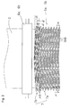
- roller members 7 arranged in rows each are constituted by a plurality of short rollers 8, 8, ⁇ arranged in a row, as shown in Fig. 2. Due to this constitution, those regions of these roller members 7 in which the resin material 2 comes into contact with the roller members do not make continuous lines but broken lines, resulting in reduced resistance of friction between the resin material 2 and the roller members 7. Consequently, the occasional occurrence of wrinkles during folding can be inhibited without fail.
- These plural short rollers 8, 8, ⁇ preferably have a reduced area of contact with the resin material 2 as described above, and each preferably have a width of 10-15 mm. It is also preferred that the rollers 8, 8, ⁇ adjacent in the respective row be arranged as close as possible to each other.
- the roller width and the space between rollers adjacent in the respective row are not limited, and it is preferred to appropriately select these taking into account the viscosity of the resin material 2, etc.
- each roller member 7 be disposed so as to form a zigzag arrangement with the plural short rollers 8, 8, ⁇ of other rows.
- this roller arrangement is employed, the regions where the roller members 7 come into contact with the resin material 2 are not continuous and, hence, a reduction in frictional resistance is attained.
- a resin material having a pressure-sensitive adhesive layer such as a pressure-sensitive adhesive sheet, the occasional occurrence of wrinkles during folding can be inhibited without fail.
- Those short rollers 8, 8, ⁇ are preferably those having a surface made of a material having a low coefficient of friction, from the standpoint of reducing friction coefficient.
- PTFE polytetrafluoroethylene
- PFA polyfluoroalkoxyl
- FEP tetrafluoroethylene/hexafluoropropylene copolymers
- CTFE polychlorotrifluoroethylene
- roller members 7 should not be construed as being limited to those constituted by the plural short rollers 8, 8, ⁇ described above.
- one long roller 9 can be used as the roller member 7 as shown in Fig. 3.
- the resin material 2 inflated into a cylindrical shape can be easily spread when deformed into a flat tube shape having an elongated elliptic section and the occasional occurrence of wrinkles in folding can be inhibited, as in the case described above.
- resin material(s) 2 in a molten state is introduced into a die 1 from one or more extruders not shown.
- the resin material 2 introduced into this die 1 is then extruded upward into a cylindrical shape through annular ejection openings concentrically formed in the die 1.
- Air is introduced into the cylindrical resin material 2 through an air introduction pipe not shown which has been formed in the die 1 to thereby inflate the resin material 2 into a cylindrical shape (see Fig. 1).
- the resin material 2 inflated into a cylindrical shape is introduced into the space between stabilizers 5a and 5b facing each other at a predetermined angle, sandwiched therebetween and pressed into a flat tube shape having an elongated elliptic section, and then introduced into the nip between a pair of pinch rollers 6a and 6b while being folded.
- the resin material 2 is folded while spreading out to both sides of the direction of forward movement, as described above, between the stabilizers 5a and 5b constituted by roller members 7 arranged in rows. Since the direction of this spreading is substantially the same as the direction of rotation of each roller member 7, the resistance of friction between the resin material 2 and each roller member 7 during the spreading is reduced and the resin material 2 is folded without arising troubles such as wrinkles.
- the resin material 2 is easily spread between the stabilizers 5a and 5b and the occasional occurrence of wrinkles is inhibited, as described above.
- Various resin materials can hence be molded.
- moldable resins include block, random, or other propylene polymers containing ethylene units as comonomer units, ethylene polymers such as low-density, high-density, and linear low-density ethylene polymers, polystyrene, polyesters, and olefin polymers which are copolymers of ethylene and other monomer(s), such as ethylene/methyl methacrylate copolymers.
- Examples thereof further include styrene/isoprene/styrene block copolymers (SIS), styrene/butadiene/styrene block copolymers (SBS), styrene/isoprene block copolymers (SI), styrene/butadiene block copolymers (SB), styrene/ethylene-propylene/styrene block copolymers (SEPS), styrene/ethylene-butylene/styrene block copolymers (SEBS), styrene/ethylene-butylene-propylene block copolymers (SEP), styrene/ethylene-butylene block copolymers (SEB), styrene/ethylene-butylene/olefin crystal block copolymers (SEBC), olefin crystal/ethylene-butylene/olefin crystal block copolymers (CEBC), st
- the method of inflation extrusion molding is applicable even to a sheet having a pressure-sensitive adhesive layer on one side, such as, e.g., a pressure-sensitive adhesive sheet.
- a pressure-sensitive adhesive sheet having no wrinkles can be formed by the method.
- the following materials may be used.
- examples of resin materials serving as a pressure-sensitive adhesive include styrene/isoprene/styrene block copolymers (SIS), styrene/butadiene/styrene block copolymers (SBS), styrene/isoprene block copolymers (SI), styrene/butadiene block copolymers (SB), styrene/ethylene-propylene/styrene block copolymers (SEPS), styrene/ethylene-butylene/styrene block copolymers (SEBS), styrene/ethylene-butylene-propylene block copolymers (SEP), styrene/ethylene-butylene block copolymers (SEB), styrene/ethylene-butylene/olefin crystal block copolymers (SEBC), olefin crystal/ethylene-butylene/olefin crystal block copo
- a tackifier (tackifier resin) may be added to the resin material.
- the tackifier can be used one or more appropriate members selected from known tackifiers for use in pressure-sensitive adhesives, such as, e.g., petroleum resins of the aliphatic type, aromatic type, aliphatic/aromatic copolymer type, or alicyclic type, coumarone-indene resins, terpene resins, terpene-phenol resins, alkylphenol resins, rosin resins, polymerized rosin resins, xylene resins, and resins obtained by hydrogenating these resins.
- one or more appropriate softeners selected from, for example, low-molecular polyisobutylene, polybutene, polyisoprene, polybutadiene, hydrogenated polyisoprene, hydrogenated polybutadiene, derivatives of these which have a reactive group, e.g., an OH group, COOH group, or epoxy group, at one or each end thereof, process oils, naphthenic oil, castor oil, linseed oil, soybean oil, phthalic ester plasticizers, phosphoric ester plasticizers, and liquid aliphatic petroleum resins.
- a reactive group e.g., an OH group, COOH group, or epoxy group
- the resin material serving as a substrate is, for example, a block, random, or other propylene polymer containing ethylene units as comonomer units, ethylene polymer, e.g., a low-density, high-density, or linear low-density ethylene polymer, polystyrene, polyester, olefin polymer which is a copolymer of ethylene and other monomer(s), e.g., an ethylene/methyl methacrylate copolymer, styrene/isoprene/styrene block copolymer (SIS), styrene/butadiene/styrene block copolymer (SBS), styrene/isoprene block copolymer (SI), stylene polymer containing ethylene units as comonomer units, ethylene polymer, e.g., a low-density, high-density, or linear low-dens
- the two resin materials introduced into the die 1 i.e., the resin material serving as a pressure-sensitive adhesive and the resin material serving as a substrate, are extruded together through the annular openings formed in the die 1 so that the resin material serving as a pressure-sensitive adhesive forms an outer layer.
- a pressure-sensitive adhesive layer is formed as an outer layer is that this constitution prevents the inside surfaces of the resultant pressure-sensitive adhesive sheet from sticking to each other upon folding between the stabilizers 5a and 5b.
- various resin materials including a pressure-sensitive adhesive sheet can be molded as high-quality film or sheet products free from wrinkles.
- a resin material for substrate formation consisting of 100 parts by weight of a resin mixture composed of 80% by weight low-density polyethylene and 20% by weight ethylene/octene-1 copolymer having a density of 0.882 g/cm 3 , 4 parts by weight of titanium oxide, and 0.2 parts by weight of natural silica (average particle diameter, 5.0 ⁇ m), and 100 parts by weight of a styrene/ethylene-butylene/styrene polymer serving as a pressure-sensitive adhesive were separately fed to the resin feed openings of respective 60-mm (diameter) screw extruders.
- the extruder for a pressure-sensitive adhesive and the extruder for a substrate were operated at revolution speeds of 15 rpm and 140 rpm, respectively, to eject these resin materials into a die 1.
- the die 1 had a diameter of 400 mm and had two annular ejection openings concentrically formed therein, and each ejection opening had a gap of 3.0 mm.
- These resin materials were molded by coextrusion under the conditions of a set temperature for the extruder for a pressure-sensitive adhesive of 220°C on the average, a set temperature for the extruder for a substrate of 180°C on the average, and a set temperature for the die 1 of 220°C.
- Each stabilizer comprised: roller rows (first roller members 7a) arranged in an 8-stage stack with a pitch H 1 of 55 mm to give a gap h 1 between adjacent first roller members 7a of 9 mm, in which each row was composed of 56 short PTFE rollers having a width of 17 mm and a roller diameter of 46 mm; and roller rows (second roller members 7b) arranged in a 2-stage stack with a pitch H 2 of 50 mm to give a gap h 2 between the two second roller members 7b of 12 mm, in which each row was composed of 90 short PTFE rollers having a width of 12 mm and a roller diameter of 38 mm.
- the gap b between the lower second roller member 7b and the uppermost first roller member 7a was set at 8 mm.
- the short rollers constituting the roller rows (the first roller members 7a and the second roller members 7b) were disposed in zigzag arrangement relative to the short rollers of adjacent roller rows, and each row was disposed symmetrically about the center of the row so as to have an angle of inclination ⁇ (see Fig. 2) of 6°.
- the inflated resin material tube was thus formed into a flat tube shape having an elongated elliptic section and folded.
- two pressure-sensitive adhesive sheets each having a thickness of 110 ⁇ m and a width of 1,350 mm could be obtained. These sheets each were free from surface wrinkles and substantially even in thickness, and were high-quality pressure-sensitive adhesive sheets.
- a resin material for substrate formation consisting of 100 parts by weight of a resin mixture composed of 75% by weight low-density polyethylene and 25% by weight ethylene/octene-1 copolymer having a density of 0.882 g/cm 3 , 4 parts by weight of titanium oxide, and 0.6 parts by weight of a lubricant, and 100 parts by weight of a styrene/ethylene-butylene random polymer serving as a pressure-sensitive adhesive were separately fed to the resin feed openings of respective 60-mm (diameter) screw extruders.
- the extruder for a pressure-sensitive adhesive and the extruder for a substrate were operated at revolution speeds of 20 rpm and 150 rpm, respectively, to eject these resin materials into a die 1.
- the die 1 had a diameter of 400 mm and had two annular ejection openings concentrically formed therein, and each ejection opening had a gap of 3.0 mm.
- These resin materials were molded by coextrusion under the conditions of a set temperature for the extruder for a pressure-sensitive adhesive of 200°C on the average, a set temperature for the extruder for a substrate of 180°C on the average, and a set temperature for the die 1 of 200°C.
- the resin materials which had been molded by coextrusion and inflated into a cylindrical shape were passed through the space between the same stabilizers 5a and 5b as in Example 1.
- the inflated resin material tube was thus formed into a flat tube shape having an elongated elliptic section and folded.
- two pressure-sensitive adhesive sheets each having a thickness of 110 ⁇ m and a width of 1,350 mm could be obtained. These sheets each were free from surface wrinkles and substantially even in thickness, and were high-quality pressure-sensitive adhesive sheets.
- a resin material for substrate formation consisting of 100 parts by weight of a resin mixture composed of 70% by weight low-density polyethylene and 30% by weight ethylene/octene-1 copolymer having a density of 0.902 g/cm 3 , 4 parts by weight of titanium oxide, and 0.1 part by weight of a weathering agent, and 100 parts by weight of a propylene copolymer serving as a pressure-sensitive adhesive were separately fed to the resin feed openings of respective 60-mm (diameter) screw extruders.
- the extruder for a pressure-sensitive adhesive and the extruder for a substrate were operated at revolution speeds of 15 rpm and 100 rpm, respectively, to eject these resin materials into a die 1.
- the die 1 had a diameter of 400 mm and had two annular ejection openings concentrically formed therein, and each ejection opening had a gap of 3.0 mm.
- These resin materials were molded by coextrusion under the conditions of a set temperature for the extruder for a pressure-sensitive adhesive of 220°C on the average, a set temperature for the extruder for a substrate of 190°C on the average, and a set temperature for the die 1 of 220°C.
- the resin materials which had been molded by coextrusion and inflated into a cylindrical shape were passed through the space between the same stabilizers 5a and 5b as in Example 1.
- the inflated resin material tube was thus formed into a flat tube shape having an elongated elliptic section and folded.
- two pressure-sensitive adhesive sheets each having a thickness of 110 ⁇ m and a width of 1,350 mm could be obtained. These sheets each were free from surface wrinkles and substantially even in thickness, and were high-quality pressure-sensitive adhesive sheets.
- Example 2 The same resin materials as in Example 1 were molded under the same conditions as in Example 1, except that the stabilizers used were ones arranged so as to have an angle of aperture ⁇ (see Fig. 1) of 24° and each consisting of rollers arranged in a 11-stage stack in which each roller had a roller diameter of 46 mm and an axial length of 1,600 mm and the rollers were disposed symmetrically about the center of the stabilizer (as shown in Fig. 3) so as to have an angle of inclination ⁇ (see Fig. 2) of 6°.
- ⁇ see Fig. 1
- the stabilizers used were ones arranged so as to have an angle of aperture ⁇ (see Fig. 1) of 24° and each consisting of rollers arranged in a 11-stage stack in which each roller had a roller diameter of 46 mm and an axial length of 1,600 mm and the rollers were disposed symmetrically about the center of the stabilizer (as shown in Fig. 3) so as to have an angle of inclination
- Example 1 The same resin materials as in Example 1 were molded under the same conditions as in Example 1, except that the stabilizers used were ones arranged so as to have an angle of aperture ⁇ (see Fig. 1) of 24° and each consisting of single-axis rollers arranged in a 11-stage stack in which each roller was made of an acrylonitrile/butadiene rubber (NBR) and had a roller diameter of 46 mm and an axial length of 1,550 mm.
- NBR acrylonitrile/butadiene rubber
- two pressure-sensitive adhesive sheets having a thickness of 110 ⁇ m and a width of 1,350 mm could be obtained. However, these sheets each had surface wrinkles which had been formed occasionally.
Landscapes
- Engineering & Computer Science (AREA)
- Mechanical Engineering (AREA)
- Physics & Mathematics (AREA)
- Thermal Sciences (AREA)
- Manufacturing & Machinery (AREA)
- Shaping By String And By Release Of Stress In Plastics And The Like (AREA)
- Extrusion Moulding Of Plastics Or The Like (AREA)
Abstract
Description
Claims (9)
- A method of inflation extrusion molding, comprising:wherein the deformation of the cylindrical inflated resin material into a flat tube shape having an elongated elliptic section is assisted by a guide device to thereby facilitate the deformation.introducing one or more resin materials extruded from one or more extruders into a die;subsequently extruding the resin material(s) from the die and inflating the extrudate into a cylindrical shape having a predetermined diameter by blown-film extrusion; and thenpassing the cylindrical inflated resin material through a space between stabilizers which face each other at a predetermined angle, to deform the cylindrical resin material into a flat tube shape having an elongated elliptic section, thereby producing a film or sheet having a predetermined width,
- The method of inflation extrusion molding of claim 1, wherein the stabilizers each comprise roller members arranged in rows and the roller members each are arranged so that the direction of rotation thereof is substantially the same as the direction in which the cylindrical inflated resin material is spread when deformed into a flat tube shape having an elongated elliptic section, to thereby serve as the guide device.
- The method of inflation extrusion molding of claim 2, wherein the roller members each comprise a plurality of rollers arranged in a row.
- An apparatus for inflation extrusion molding, comprising:wherein the stabilizers comprises roller members arranged in rows, and the roller members each are arranged so that the direction of rotation thereof is substantially the same as the direction in which the cylindrical inflated resin material is spread when deformed into a flat tube shape having an elongated elliptic section.a die into which one or more resin materials extruded from one or more respective extruders are introduced, and subsequently from which the introduced one or more resin materials are extruded and inflated into a cylindrical shape having a predetermined diameter by blown-film extrusion; andstabilizers facing each other at a predetermined angle and defining a space therebetween through which the cylindrical inflated resin material is passed to be deformed into a flat tube shape having an elongated elliptic section, thereby producing a film or sheet having a predetermined width,
- The apparatus for inflation extrusion molding of claim 4, wherein the roller members arranged in rows are arranged so as to give a gap between adjacent roller members of not larger than the diameter of each roller member.
- The apparatus for inflation extrusion molding of claim 4 or 5, wherein the roller members each comprise a plurality of rollers arranged in a row.
- A process for producing a pressure-sensitive adhesive sheet, comprising:wherein the deformation of the cylindrical inflated resin materials into a flat tube shape having an elongated elliptic section is assisted by a guide device to thereby facilitate the deformation.extruding a resin material for forming a pressure-sensitive adhesive layer and a resin material for forming a substrate from respective separate extruders;introducing the extrudates into a single die;subsequently extruding the introduced resin materials together from the die;inflating the extrudate into a cylindrical shape having a predetermined diameter by blown-film extrusion; and thenpassing the cylindrical inflated resin materials through a space between stabilizers which face each other at a predetermined angle, to deform the cylindrical materials into a flat tube shape having an elongated elliptic section, thereby producing a pressure-sensitive adhesive sheet having a predetermined width,
- The process for producing a pressure-sensitive adhesive sheet of claim 7, wherein the stabilizers comprise roller members arranged in rows and the roller members each are arranged so that the direction of rotation thereof is substantially the same as the direction in which the cylindrical inflated resin materials are spread when deformed into a flat tube shape having an elongated elliptic section, to thereby serve as the guide device.
- The process for producing a pressure-sensitive adhesive sheet of claim 8, wherein the roller members each comprise a plurality of rollers arranged in a row.
Applications Claiming Priority (2)
| Application Number | Priority Date | Filing Date | Title |
|---|---|---|---|
| JP2003324534 | 2003-09-17 | ||
| JP2003324534 | 2003-09-17 |
Publications (3)
| Publication Number | Publication Date |
|---|---|
| EP1516712A2 true EP1516712A2 (en) | 2005-03-23 |
| EP1516712A3 EP1516712A3 (en) | 2009-12-02 |
| EP1516712B1 EP1516712B1 (en) | 2014-01-01 |
Family
ID=34191304
Family Applications (1)
| Application Number | Title | Priority Date | Filing Date |
|---|---|---|---|
| EP04022191.3A Expired - Lifetime EP1516712B1 (en) | 2003-09-17 | 2004-09-17 | Method of inflation extrusion molding, extrusion molding apparatus therefor, and process for producing pressure-sensitive adhesive sheet |
Country Status (5)
| Country | Link |
|---|---|
| US (1) | US7556762B2 (en) |
| EP (1) | EP1516712B1 (en) |
| KR (1) | KR100704091B1 (en) |
| CN (1) | CN100503214C (en) |
| TW (1) | TWI270457B (en) |
Cited By (2)
| Publication number | Priority date | Publication date | Assignee | Title |
|---|---|---|---|---|
| WO2009133190A1 (en) * | 2008-04-30 | 2009-11-05 | Tesa Se | Adhesive tape carrier film made of polyolefin and use thereof |
| EP2368687A3 (en) * | 2010-03-26 | 2012-02-08 | Nitto Denko Corporation | Apparatus and method for inflation extrusion molding of pressure-sensitive adhesive sheet |
Families Citing this family (17)
| Publication number | Priority date | Publication date | Assignee | Title |
|---|---|---|---|---|
| DE10352976A1 (en) * | 2003-11-13 | 2005-06-09 | Kiefel Extrusion Gmbh | Flat laying device with spreading roller for blown film lines |
| US20090117379A1 (en) * | 2005-06-06 | 2009-05-07 | Katsunori Toyoshima | Surface protection film |
| DE102006027644A1 (en) * | 2006-06-13 | 2007-12-27 | Windmöller & Hölscher Kg | Calibration device for a blown film plant |
| CN102398363A (en) * | 2011-07-22 | 2012-04-04 | 苏州天加新材料有限公司 | Four-side film retaining mechanism for herringbone roller clamping frame |
| CN103254810A (en) * | 2012-02-15 | 2013-08-21 | 日东电工株式会社 | Surface protection sheet |
| KR200472091Y1 (en) * | 2013-11-28 | 2014-04-04 | 강호관 | thin sheet manufacturing apparatus |
| US9702938B2 (en) * | 2015-03-18 | 2017-07-11 | Caterpillar Inc. | Method and apparatus for detecting phase imbalance of an electrical component in a machine |
| US11104054B2 (en) | 2016-01-15 | 2021-08-31 | Addex, Inc. | High performance cooling system |
| US11298865B2 (en) * | 2016-01-15 | 2022-04-12 | Addex, Inc. | High performance cooling system |
| US11292176B2 (en) * | 2016-01-15 | 2022-04-05 | Addex, Inc. | High performance cooling system |
| US10486353B2 (en) | 2016-07-11 | 2019-11-26 | Yonit Rose | Environmentally friendly dry cleaning bags and methods of making same |
| CN106313635A (en) * | 2016-08-25 | 2017-01-11 | 江苏万乐复合材料有限公司 | Inner film bag crease preventing method based on fully-automatic cutting, covering and sewing all-in-one machine for woven bags |
| JP7055973B2 (en) | 2016-12-09 | 2022-04-19 | スリーエム イノベイティブ プロパティズ カンパニー | Polymer multilayer film |
| CN110049871B (en) | 2016-12-09 | 2021-05-14 | 3M创新有限公司 | Polymeric multilayer film |
| CN110049862B (en) | 2016-12-09 | 2021-09-28 | 3M创新有限公司 | Articles comprising multilayer films |
| JP7129411B2 (en) | 2016-12-09 | 2022-09-01 | スリーエム イノベイティブ プロパティズ カンパニー | polymer multilayer film |
| CN112659514B (en) * | 2020-12-24 | 2022-08-16 | 辽宁丰收塑业有限责任公司 | High-temperature processing device for film production |
Family Cites Families (31)
| Publication number | Priority date | Publication date | Assignee | Title |
|---|---|---|---|---|
| US3157720A (en) * | 1960-07-13 | 1964-11-17 | Dow Chemical Co | Method and apparatus for trapped bubble stretching of thermoplastic film |
| US3315308A (en) * | 1962-02-15 | 1967-04-25 | Phillips Petroleum Co | Continuous production of biaxially oriented, crystalline, thermoplastic film |
| US3223762A (en) * | 1962-10-10 | 1965-12-14 | Fmc Corp | Manufacture of thin-wall tubing |
| US3311682A (en) * | 1963-10-21 | 1967-03-28 | Gulf Oil Corp | Process for extrusion of tubular plastic film with external and internal spray cooling |
| US3355531A (en) * | 1965-05-13 | 1967-11-28 | Dow Chemical Co | Method and apparatus for the preparation of thermoplastic resinous film |
| DE1553027C2 (en) * | 1965-08-23 | 1983-02-24 | Eckerle, Otto, 7502 Malsch | Internal gear pump |
| CH521217A (en) * | 1969-10-08 | 1972-04-15 | Windmoeller & Hoelscher | Process for air cooling of the plastic film tube blown by a film blow head and device for carrying out the process |
| JPS5020578B1 (en) | 1970-10-27 | 1975-07-16 | ||
| US3775523A (en) * | 1971-03-04 | 1973-11-27 | Fmc Corp | Method and apparatus for making oriented tubular film |
| GB1465188A (en) * | 1973-04-09 | 1977-02-23 | Gen Electric | Apparatus for collapsing blown tubes |
| US4355966A (en) * | 1981-05-04 | 1982-10-26 | E. B. Westlake, Jr. | Automatic control of bubble size in blown film |
| JPS5881128A (en) * | 1981-11-09 | 1983-05-16 | Mitsui Petrochem Ind Ltd | Manufacture of inflation film and apparatus therefor |
| US4533309A (en) * | 1983-06-15 | 1985-08-06 | Mirek Planeta | Collapsing frame for moving tubes of plastic material |
| JPS6049910A (en) * | 1983-08-30 | 1985-03-19 | Dainippon Printing Co Ltd | Manufacture of synthetic resin mono-layered film having property of thermoplastic polyester film |
| JPS60262618A (en) | 1984-06-11 | 1985-12-26 | Mitsubishi Chem Ind Ltd | Manufacture of film |
| JPS61148026A (en) | 1984-12-24 | 1986-07-05 | Tomy Kikai Kogyo Kk | Bubble guide device of inflation film molding machine |
| US4749346A (en) * | 1986-10-30 | 1988-06-07 | Mirek Planeta | Apparatus for the production of plastic film |
| US5089320A (en) * | 1989-01-09 | 1992-02-18 | James River Ii, Inc. | Resealable packaging material |
| JPH0390332A (en) | 1989-09-04 | 1991-04-16 | Sekisui Chem Co Ltd | Film guiding device |
| CA2104552C (en) * | 1992-09-16 | 2000-02-29 | Mirek Planeta | Collapsing frame for moving tubes of plastic material |
| JPH06143410A (en) * | 1992-11-10 | 1994-05-24 | Sekisui Chem Co Ltd | Inflation film thickness control device |
| JPH06143411A (en) | 1992-11-10 | 1994-05-24 | Sekisui Chem Co Ltd | Focusing device for blown film |
| KR950003316U (en) * | 1993-07-15 | 1995-02-16 | 김상영 | Stabilizer plate of inflation film extruder |
| JP2786082B2 (en) * | 1993-08-10 | 1998-08-13 | 積水化学工業株式会社 | Automatic size change control system in inflation molding line |
| KR200154649Y1 (en) | 1996-07-31 | 1999-08-16 | 윤재일 | Reinforcing silk for vinyl house |
| TW379272B (en) * | 1998-03-05 | 2000-01-11 | Longmeng Environmental Papers | Method of manufacturing recycling papers |
| JPH11300825A (en) * | 1998-04-17 | 1999-11-02 | Idemitsu Petrochem Co Ltd | Inflation molding of resin film |
| JP3984391B2 (en) * | 1999-04-07 | 2007-10-03 | 株式会社クラレ | Inflation film forming apparatus and forming method |
| TW490384B (en) * | 1999-12-13 | 2002-06-11 | Sumitomo Chemical Co | Resin guiding device for inflation molding apparatus and method of producing film |
| DE10140577B4 (en) * | 2001-08-18 | 2008-05-15 | Windmöller & Hölscher Kg | Braking rollers of the flattening device of extruded film hoses and method of operation |
| KR100953316B1 (en) | 2008-07-23 | 2010-04-20 | 현대자동차주식회사 | Shock Absorber for Roll Control |
-
2004
- 2004-09-16 US US10/942,139 patent/US7556762B2/en not_active Expired - Fee Related
- 2004-09-17 TW TW093128171A patent/TWI270457B/en not_active IP Right Cessation
- 2004-09-17 CN CNB2004100787066A patent/CN100503214C/en not_active Expired - Fee Related
- 2004-09-17 KR KR1020040074662A patent/KR100704091B1/en not_active Expired - Fee Related
- 2004-09-17 EP EP04022191.3A patent/EP1516712B1/en not_active Expired - Lifetime
Cited By (3)
| Publication number | Priority date | Publication date | Assignee | Title |
|---|---|---|---|---|
| WO2009133190A1 (en) * | 2008-04-30 | 2009-11-05 | Tesa Se | Adhesive tape carrier film made of polyolefin and use thereof |
| EP2368687A3 (en) * | 2010-03-26 | 2012-02-08 | Nitto Denko Corporation | Apparatus and method for inflation extrusion molding of pressure-sensitive adhesive sheet |
| US8226398B2 (en) | 2010-03-26 | 2012-07-24 | Nitto Denko Corporation | Apparatus and method for inflation extrusion molding of pressure-sensitive adhesive sheet |
Also Published As
| Publication number | Publication date |
|---|---|
| EP1516712A3 (en) | 2009-12-02 |
| US20050056973A1 (en) | 2005-03-17 |
| CN100503214C (en) | 2009-06-24 |
| TW200528262A (en) | 2005-09-01 |
| US7556762B2 (en) | 2009-07-07 |
| KR100704091B1 (en) | 2007-04-05 |
| KR20050028861A (en) | 2005-03-23 |
| TWI270457B (en) | 2007-01-11 |
| CN1597302A (en) | 2005-03-23 |
| EP1516712B1 (en) | 2014-01-01 |
Similar Documents
| Publication | Publication Date | Title |
|---|---|---|
| US7556762B2 (en) | Method of inflation extrusion molding, extrusion molding apparatus therefor, and process for producing pressure-sensitive adhesive sheet | |
| AU2002326719B2 (en) | Integrated process for making inflatable article | |
| US4474634A (en) | Process for producing a laminated film or sheet structure | |
| US5747107A (en) | Method of applying a hot melt coating | |
| AU2005227415A1 (en) | Process and apparatus for making heat-sealed articles | |
| US8226398B2 (en) | Apparatus and method for inflation extrusion molding of pressure-sensitive adhesive sheet | |
| JP4401908B2 (en) | Inflation extrusion molding method, extrusion molding apparatus used therefor, and pressure-sensitive adhesive sheet manufacturing method | |
| JP4574260B2 (en) | Manufacturing method of resin film and edge pinning device for resin film molding | |
| JP7501274B2 (en) | Sheet forming die | |
| WO1996030194A1 (en) | Improved thin lcp film process | |
| JP3623549B2 (en) | Extrusion film forming method | |
| EP1736311A1 (en) | Method and apparatus for fabrication of laminates | |
| JPH11291344A (en) | Manufacturing method of embossed film | |
| JP2006081996A (en) | Bar coating method | |
| GB1603128A (en) | Tubular plastics film | |
| JP2020049229A (en) | Medical packaging sheet and medical packaging material | |
| JP2004059062A (en) | Lid material and manufacturing method of package | |
| JPH05116217A (en) | Tubular film forming equipment | |
| JPS6111184B2 (en) | ||
| JPS6169458A (en) | Multilayer laminated film |
Legal Events
| Date | Code | Title | Description |
|---|---|---|---|
| PUAI | Public reference made under article 153(3) epc to a published international application that has entered the european phase |
Free format text: ORIGINAL CODE: 0009012 |
|
| AK | Designated contracting states |
Kind code of ref document: A2 Designated state(s): AT BE BG CH CY CZ DE DK EE ES FI FR GB GR HU IE IT LI LU MC NL PL PT RO SE SI SK TR |
|
| AX | Request for extension of the european patent |
Extension state: AL HR LT LV MK |
|
| RIC1 | Information provided on ipc code assigned before grant |
Ipc: B29C 53/10 20060101ALN20090721BHEP Ipc: B29C 47/00 20060101ALI20090721BHEP Ipc: B29C 47/90 20060101AFI20090721BHEP |
|
| PUAL | Search report despatched |
Free format text: ORIGINAL CODE: 0009013 |
|
| AK | Designated contracting states |
Kind code of ref document: A3 Designated state(s): AT BE BG CH CY CZ DE DK EE ES FI FR GB GR HU IE IT LI LU MC NL PL PT RO SE SI SK TR |
|
| AX | Request for extension of the european patent |
Extension state: AL HR LT LV MK |
|
| 17P | Request for examination filed |
Effective date: 20100531 |
|
| AKX | Designation fees paid |
Designated state(s): AT BE BG CH CY CZ DE DK EE ES FI FR GB GR HU IE IT LI LU MC NL PL PT RO SE SI SK TR |
|
| GRAP | Despatch of communication of intention to grant a patent |
Free format text: ORIGINAL CODE: EPIDOSNIGR1 |
|
| INTG | Intention to grant announced |
Effective date: 20130715 |
|
| RIN1 | Information on inventor provided before grant (corrected) |
Inventor name: NATSUME, MASAYOSHI Inventor name: OOYAMA, KOOKI Inventor name: HAYASHI, KEIJI Inventor name: TORII, TADAO |
|
| GRAS | Grant fee paid |
Free format text: ORIGINAL CODE: EPIDOSNIGR3 |
|
| GRAA | (expected) grant |
Free format text: ORIGINAL CODE: 0009210 |
|
| AK | Designated contracting states |
Kind code of ref document: B1 Designated state(s): AT BE BG CH CY CZ DE DK EE ES FI FR GB GR HU IE IT LI LU MC NL PL PT RO SE SI SK TR |
|
| REG | Reference to a national code |
Ref country code: GB Ref legal event code: FG4D |
|
| REG | Reference to a national code |
Ref country code: CH Ref legal event code: EP |
|
| REG | Reference to a national code |
Ref country code: IE Ref legal event code: FG4D |
|
| REG | Reference to a national code |
Ref country code: DE Ref legal event code: R096 Ref document number: 602004044127 Country of ref document: DE Effective date: 20140213 |
|
| REG | Reference to a national code |
Ref country code: AT Ref legal event code: REF Ref document number: 647401 Country of ref document: AT Kind code of ref document: T Effective date: 20140215 |
|
| REG | Reference to a national code |
Ref country code: NL Ref legal event code: VDEP Effective date: 20140101 |
|
| REG | Reference to a national code |
Ref country code: AT Ref legal event code: MK05 Ref document number: 647401 Country of ref document: AT Kind code of ref document: T Effective date: 20140101 |
|
| PG25 | Lapsed in a contracting state [announced via postgrant information from national office to epo] |
Ref country code: SE Free format text: LAPSE BECAUSE OF FAILURE TO SUBMIT A TRANSLATION OF THE DESCRIPTION OR TO PAY THE FEE WITHIN THE PRESCRIBED TIME-LIMIT Effective date: 20140101 Ref country code: CY Free format text: LAPSE BECAUSE OF FAILURE TO SUBMIT A TRANSLATION OF THE DESCRIPTION OR TO PAY THE FEE WITHIN THE PRESCRIBED TIME-LIMIT Effective date: 20140101 Ref country code: PT Free format text: LAPSE BECAUSE OF FAILURE TO SUBMIT A TRANSLATION OF THE DESCRIPTION OR TO PAY THE FEE WITHIN THE PRESCRIBED TIME-LIMIT Effective date: 20140502 Ref country code: FI Free format text: LAPSE BECAUSE OF FAILURE TO SUBMIT A TRANSLATION OF THE DESCRIPTION OR TO PAY THE FEE WITHIN THE PRESCRIBED TIME-LIMIT Effective date: 20140101 Ref country code: NL Free format text: LAPSE BECAUSE OF FAILURE TO SUBMIT A TRANSLATION OF THE DESCRIPTION OR TO PAY THE FEE WITHIN THE PRESCRIBED TIME-LIMIT Effective date: 20140101 Ref country code: AT Free format text: LAPSE BECAUSE OF FAILURE TO SUBMIT A TRANSLATION OF THE DESCRIPTION OR TO PAY THE FEE WITHIN THE PRESCRIBED TIME-LIMIT Effective date: 20140101 Ref country code: ES Free format text: LAPSE BECAUSE OF FAILURE TO SUBMIT A TRANSLATION OF THE DESCRIPTION OR TO PAY THE FEE WITHIN THE PRESCRIBED TIME-LIMIT Effective date: 20140101 |
|
| REG | Reference to a national code |
Ref country code: DE Ref legal event code: R097 Ref document number: 602004044127 Country of ref document: DE |
|
| PG25 | Lapsed in a contracting state [announced via postgrant information from national office to epo] |
Ref country code: DK Free format text: LAPSE BECAUSE OF FAILURE TO SUBMIT A TRANSLATION OF THE DESCRIPTION OR TO PAY THE FEE WITHIN THE PRESCRIBED TIME-LIMIT Effective date: 20140101 Ref country code: EE Free format text: LAPSE BECAUSE OF FAILURE TO SUBMIT A TRANSLATION OF THE DESCRIPTION OR TO PAY THE FEE WITHIN THE PRESCRIBED TIME-LIMIT Effective date: 20140101 Ref country code: RO Free format text: LAPSE BECAUSE OF FAILURE TO SUBMIT A TRANSLATION OF THE DESCRIPTION OR TO PAY THE FEE WITHIN THE PRESCRIBED TIME-LIMIT Effective date: 20140101 Ref country code: CZ Free format text: LAPSE BECAUSE OF FAILURE TO SUBMIT A TRANSLATION OF THE DESCRIPTION OR TO PAY THE FEE WITHIN THE PRESCRIBED TIME-LIMIT Effective date: 20140101 |
|
| PLBE | No opposition filed within time limit |
Free format text: ORIGINAL CODE: 0009261 |
|
| STAA | Information on the status of an ep patent application or granted ep patent |
Free format text: STATUS: NO OPPOSITION FILED WITHIN TIME LIMIT |
|
| PG25 | Lapsed in a contracting state [announced via postgrant information from national office to epo] |
Ref country code: SK Free format text: LAPSE BECAUSE OF FAILURE TO SUBMIT A TRANSLATION OF THE DESCRIPTION OR TO PAY THE FEE WITHIN THE PRESCRIBED TIME-LIMIT Effective date: 20140101 Ref country code: PL Free format text: LAPSE BECAUSE OF FAILURE TO SUBMIT A TRANSLATION OF THE DESCRIPTION OR TO PAY THE FEE WITHIN THE PRESCRIBED TIME-LIMIT Effective date: 20140101 |
|
| 26N | No opposition filed |
Effective date: 20141002 |
|
| REG | Reference to a national code |
Ref country code: DE Ref legal event code: R097 Ref document number: 602004044127 Country of ref document: DE Effective date: 20141002 |
|
| PG25 | Lapsed in a contracting state [announced via postgrant information from national office to epo] |
Ref country code: MC Free format text: LAPSE BECAUSE OF FAILURE TO SUBMIT A TRANSLATION OF THE DESCRIPTION OR TO PAY THE FEE WITHIN THE PRESCRIBED TIME-LIMIT Effective date: 20140101 Ref country code: LU Free format text: LAPSE BECAUSE OF FAILURE TO SUBMIT A TRANSLATION OF THE DESCRIPTION OR TO PAY THE FEE WITHIN THE PRESCRIBED TIME-LIMIT Effective date: 20140917 |
|
| REG | Reference to a national code |
Ref country code: CH Ref legal event code: PL |
|
| GBPC | Gb: european patent ceased through non-payment of renewal fee |
Effective date: 20140917 |
|
| PG25 | Lapsed in a contracting state [announced via postgrant information from national office to epo] |
Ref country code: SI Free format text: LAPSE BECAUSE OF FAILURE TO SUBMIT A TRANSLATION OF THE DESCRIPTION OR TO PAY THE FEE WITHIN THE PRESCRIBED TIME-LIMIT Effective date: 20140101 |
|
| REG | Reference to a national code |
Ref country code: IE Ref legal event code: MM4A |
|
| PG25 | Lapsed in a contracting state [announced via postgrant information from national office to epo] |
Ref country code: GB Free format text: LAPSE BECAUSE OF NON-PAYMENT OF DUE FEES Effective date: 20140917 Ref country code: LI Free format text: LAPSE BECAUSE OF NON-PAYMENT OF DUE FEES Effective date: 20140930 Ref country code: CH Free format text: LAPSE BECAUSE OF NON-PAYMENT OF DUE FEES Effective date: 20140930 |
|
| REG | Reference to a national code |
Ref country code: FR Ref legal event code: PLFP Year of fee payment: 12 |
|
| PG25 | Lapsed in a contracting state [announced via postgrant information from national office to epo] |
Ref country code: IE Free format text: LAPSE BECAUSE OF NON-PAYMENT OF DUE FEES Effective date: 20140917 |
|
| PGFP | Annual fee paid to national office [announced via postgrant information from national office to epo] |
Ref country code: DE Payment date: 20150908 Year of fee payment: 12 |
|
| PGFP | Annual fee paid to national office [announced via postgrant information from national office to epo] |
Ref country code: FR Payment date: 20150811 Year of fee payment: 12 Ref country code: BE Payment date: 20150911 Year of fee payment: 12 |
|
| PGFP | Annual fee paid to national office [announced via postgrant information from national office to epo] |
Ref country code: IT Payment date: 20150925 Year of fee payment: 12 |
|
| PG25 | Lapsed in a contracting state [announced via postgrant information from national office to epo] |
Ref country code: BG Free format text: LAPSE BECAUSE OF FAILURE TO SUBMIT A TRANSLATION OF THE DESCRIPTION OR TO PAY THE FEE WITHIN THE PRESCRIBED TIME-LIMIT Effective date: 20140101 |
|
| PG25 | Lapsed in a contracting state [announced via postgrant information from national office to epo] |
Ref country code: GR Free format text: LAPSE BECAUSE OF FAILURE TO SUBMIT A TRANSLATION OF THE DESCRIPTION OR TO PAY THE FEE WITHIN THE PRESCRIBED TIME-LIMIT Effective date: 20140402 |
|
| PG25 | Lapsed in a contracting state [announced via postgrant information from national office to epo] |
Ref country code: HU Free format text: LAPSE BECAUSE OF FAILURE TO SUBMIT A TRANSLATION OF THE DESCRIPTION OR TO PAY THE FEE WITHIN THE PRESCRIBED TIME-LIMIT; INVALID AB INITIO Effective date: 20040917 |
|
| PG25 | Lapsed in a contracting state [announced via postgrant information from national office to epo] |
Ref country code: BE Free format text: LAPSE BECAUSE OF NON-PAYMENT OF DUE FEES Effective date: 20160930 |
|
| REG | Reference to a national code |
Ref country code: DE Ref legal event code: R119 Ref document number: 602004044127 Country of ref document: DE |
|
| REG | Reference to a national code |
Ref country code: FR Ref legal event code: ST Effective date: 20170531 |
|
| PG25 | Lapsed in a contracting state [announced via postgrant information from national office to epo] |
Ref country code: DE Free format text: LAPSE BECAUSE OF NON-PAYMENT OF DUE FEES Effective date: 20170401 Ref country code: FR Free format text: LAPSE BECAUSE OF NON-PAYMENT OF DUE FEES Effective date: 20160930 |
|
| PG25 | Lapsed in a contracting state [announced via postgrant information from national office to epo] |
Ref country code: IT Free format text: LAPSE BECAUSE OF NON-PAYMENT OF DUE FEES Effective date: 20160917 |
|
| REG | Reference to a national code |
Ref country code: BE Ref legal event code: MM Effective date: 20160930 |
|
| PGFP | Annual fee paid to national office [announced via postgrant information from national office to epo] |
Ref country code: TR Payment date: 20200911 Year of fee payment: 17 |
|
| PG25 | Lapsed in a contracting state [announced via postgrant information from national office to epo] |
Ref country code: TR Free format text: LAPSE BECAUSE OF NON-PAYMENT OF DUE FEES Effective date: 20210917 |