EP1516682A1 - Verfahren und Vorrichtung zum Spülen und Entleeren eines mit feststoffartigen Rückständen gefüllten Rückstandtanks einer biologischen Kläranlage - Google Patents
Verfahren und Vorrichtung zum Spülen und Entleeren eines mit feststoffartigen Rückständen gefüllten Rückstandtanks einer biologischen Kläranlage Download PDFInfo
- Publication number
- EP1516682A1 EP1516682A1 EP04021191A EP04021191A EP1516682A1 EP 1516682 A1 EP1516682 A1 EP 1516682A1 EP 04021191 A EP04021191 A EP 04021191A EP 04021191 A EP04021191 A EP 04021191A EP 1516682 A1 EP1516682 A1 EP 1516682A1
- Authority
- EP
- European Patent Office
- Prior art keywords
- tank
- liquid
- residue
- suction
- residues
- Prior art date
- Legal status (The legal status is an assumption and is not a legal conclusion. Google has not performed a legal analysis and makes no representation as to the accuracy of the status listed.)
- Granted
Links
- 238000000034 method Methods 0.000 title claims abstract description 46
- 239000010865 sewage Substances 0.000 title claims description 4
- 238000011010 flushing procedure Methods 0.000 title 1
- 238000009434 installation Methods 0.000 title 1
- 238000004140 cleaning Methods 0.000 claims abstract description 45
- XLYOFNOQVPJJNP-UHFFFAOYSA-N water Substances O XLYOFNOQVPJJNP-UHFFFAOYSA-N 0.000 claims abstract description 38
- 239000012530 fluid Substances 0.000 claims abstract 3
- 239000007788 liquid Substances 0.000 claims description 47
- 238000003756 stirring Methods 0.000 claims description 6
- 238000004065 wastewater treatment Methods 0.000 claims description 6
- 238000001514 detection method Methods 0.000 claims description 3
- 239000007787 solid Substances 0.000 abstract description 8
- 239000000463 material Substances 0.000 description 9
- 210000003608 fece Anatomy 0.000 description 2
- 238000005259 measurement Methods 0.000 description 2
- 241000196324 Embryophyta Species 0.000 description 1
- 235000003560 Valerianella locusta Nutrition 0.000 description 1
- 240000004668 Valerianella locusta Species 0.000 description 1
- 230000003044 adaptive effect Effects 0.000 description 1
- 230000009286 beneficial effect Effects 0.000 description 1
- 230000008878 coupling Effects 0.000 description 1
- 238000010168 coupling process Methods 0.000 description 1
- 238000005859 coupling reaction Methods 0.000 description 1
- 238000007599 discharging Methods 0.000 description 1
- 238000000605 extraction Methods 0.000 description 1
- 230000001939 inductive effect Effects 0.000 description 1
- 238000000746 purification Methods 0.000 description 1
- 239000008237 rinsing water Substances 0.000 description 1
Images

Classifications
-
- B—PERFORMING OPERATIONS; TRANSPORTING
- B08—CLEANING
- B08B—CLEANING IN GENERAL; PREVENTION OF FOULING IN GENERAL
- B08B5/00—Cleaning by methods involving the use of air flow or gas flow
- B08B5/02—Cleaning by the force of jets, e.g. blowing-out cavities
-
- B—PERFORMING OPERATIONS; TRANSPORTING
- B08—CLEANING
- B08B—CLEANING IN GENERAL; PREVENTION OF FOULING IN GENERAL
- B08B9/00—Cleaning hollow articles by methods or apparatus specially adapted thereto
- B08B9/08—Cleaning containers, e.g. tanks
-
- B—PERFORMING OPERATIONS; TRANSPORTING
- B08—CLEANING
- B08B—CLEANING IN GENERAL; PREVENTION OF FOULING IN GENERAL
- B08B9/00—Cleaning hollow articles by methods or apparatus specially adapted thereto
- B08B9/08—Cleaning containers, e.g. tanks
- B08B9/093—Cleaning containers, e.g. tanks by the force of jets or sprays
Definitions
- the present invention relates to a method and a corresponding Device for cleaning and emptying one with solids-like residues filled residue tanks of a biological wastewater treatment plant, as for example used in passenger trains.
- the French Bahn uses, for example, vacuum toilets with "eau di", while the German and Austrian railway vacuum toilets with conventional Use rinsing water.
- organic toilets which are used for example by the Swiss railway.
- the present invention is therefore based on the object, an improved Method and an improved device for rinsing and emptying to provide the residue tanks of a biological wastewater treatment plant with which can achieve improved cleaning results and preferably allow automation of the cleaning and emptying process.
- the present invention is based on the idea of the purification process to run according to a defined scheme. Furthermore it was recognized that it is beneficial when vacuuming the softened and Whirled residues from the tank at least temporarily at the same time continue to supply liquid for suction and / or in suction pauses, because it can achieve an improved cleaning result. Especially this achieves an improved softening of the residues, and the mass discharged from the tank is thereby diluted so that it can be better derived from the tank. Furthermore, an overflow of the Tank to be prevented.
- the method according to the invention can be automated in a simple manner, so that it no longer depends on a user, whether, how often, how long and in what order which steps of the method are performed. Based on empirical values, the durations of the individual Steps and other parameters, such as the pressure of the supplied Medium, the amount of liquid supplied and in particular the Times and durations of the liquid supply during the suction process be set. Operating errors, in the known method can lead to poor cleaning results are thus largely ruled out, and it can be ensured that the residue tank always completely emptied and thoroughly rinsed.
- the amount of liquid supplied and the sucked residue amount are detected, for which appropriate Flow measuring means are provided, for example, an inductive Flow meter for measuring the amount coming out of the tank Solids, and that the supply of liquid into the tank during aspiration is controlled so that the tank does not overflow.
- appropriate Flow measuring means for example, an inductive Flow meter for measuring the amount coming out of the tank Solids, and that the supply of liquid into the tank during aspiration is controlled so that the tank does not overflow.
- the supply the liquid in the first step and the supply of the high pressure Medium at least temporarily at the same time in the second step, especially completely at the same time and by supplying an under High-pressure liquid, in particular water, take place.
- the first and second step are thus summarized, so that the soothing of the Residues and whirling occur substantially simultaneously.
- These Design is used in particular when no supply with compressed air is available, but only a supply of Water or other liquid under high pressure.
- design can also be provided that the supply of the liquid and the supply of the high-pressure medium (in particular Air) through a single supply line internally, for example, split into two is, is realized.
- the extracted residue quantity is detected, for which purpose suitable residue flow means provided are, and that the cleaning process starts again when the Do not aspirate a first predetermined over a predetermined period of time Residue is sucked off. So it can be determined if that Softening and stirring up the residues was sufficient, so that the Residues can be sucked off. If not enough residue have been softened and stirred up, this is in this embodiment the method according to the invention automatically detected and leads to a new start of the procedure.
- the detection result of the residue amount may be used will determine if a second predetermined amount of residue sucked was so that the tank is completely empty of residues.
- the second Residual amount can be a corresponding to the tank size and possibly be according to the cleaning interval certain experience size.
- the individual steps of the invention take place Method in a preferred embodiment timed and automatic, the parameters of the timing to be cleaned and emptying tank are customizable.
- the inventive Device and the inventive method also adaptive be configured to the parameters according to learned experience to hire or improve independently.
- the device according to the invention is a mobile device configured, wherein the liquid supply means a liquid reservoir and the suction device comprises a vacuum pump. Further may be used to supply the medium (e.g., air) under high pressure suitable device, e.g. a compressor, be provided.
- suitable device e.g. a compressor
- the liquid supply means a liquid connection for connection to a liquid supply line
- the suction device have a vacuum connection for connection to a vacuum line.
- several such stationary devices can be used in one Cleaning hall for trains to be arranged at certain intervals Simultaneously several bio-toilets of the train to be cleaned to empty and to clean.
- sensor means for determining whether the liquid supply device, the medium supply device and the suction device with the tank are provided, are provided.
- the sensor means can be determined be sure that the device is correctly coupled to the tank, so that a faulty cleaning due to faulty or unconnected lines, as is possible in the known device are excluded can.
- Such sensor means may, for example, special signal generator or simple grounding lines to the connecting lines.
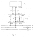
- Fig. 1 shows schematically a first embodiment of an inventive Device for cleaning and emptying the residue tank of a biological Wastewater treatment plant.
- the residue tank is referred to, in which some time a solid and dry mass of toilet paper, fecal matter and solid bodies as residues and therefore emptied from time to time and needs to be cleaned.
- the tank has three connections, namely a first connection 11 for connecting a compressed air line L, a second port 12 for connecting a water supply W and a third terminal 13 for connection of a suction line V.
- the inventive Cleaning device 2 has corresponding connections 21, 22, 23 to, in the present embodiment, stationary designed cleaning device 2 with compressed air or water to supply or the residues suck.
- input terminals 31 and 32 are provided, with which the cleaning device 2 to a compressed air supply line 51st or a water supply line can be connected.
- a discharge port 33 is further provided, with which the Cleaning device 2 connected to a vacuum supply line 53 can be at the suction vacuum for sucking the residues is provided from the tank 1.
- the output terminals 21, 22, 23 are connected to the supply terminals 31, 32, 33 connected by controlled valves 41, 42, 43, which means a control device 24 are controllable. Further, in the connection line between water supply inlet 32 and water outlet 22 a Water flow meter 25 and in the connecting line between vacuum supply input 33 and vacuum outlet 23 a residue flowmeter 26 provided with which the introduced into the tank 1 amount of water or the amount of residue withdrawn from the tank can be.
- a second method step S2 the partial or can overlap completely with method step S1, Compressed air is introduced into the tank 1 to that of the introduced water to stir up softened residue material.
- the valve 41 for a opened for a predetermined period of time.
- the actual suction takes place of the softened and fluidized residue material.
- first (S3) by opening the valve 43 for a predetermined Period of time the vacuum applied to a first part of the softened and to suck up swirled residue material. But a better one
- the cleaning and emptying results are then simultaneously or shortly after the valves 42 and 43 are opened, at least temporarily at the same time introduce water into the tank 1 and residue material to suck out of the tank.
- step S5 is whether any residue material has been sucked or whether the sucked Residue amount above R is above a certain limit R1. So it may happen, for example, that in steps S1 and S4 the supplied water was insufficient to soften the residue material, so that afterwards only very little or no residue material is sucked off could be. If so, the process is restarted by started with step S1, including, for example, in step S1 More water can be added to the residue material again (and possibly better) soften. However, if it is determined in step S5 that sufficient residue material has been sucked off, can continue with the suction process (S6), which can also be repeated several times, continued be to cause a complete emptying and cleaning of the tank 1.
- S6 suction process
- step S7 a further check can optionally also be provided be tested on the basis of the determined, sucked residue amount R whether there is more than a second limit value R2 for the residue quantity was sucked off.
- the second limit value R2 may be, for example, empirical determined limit value that indicates for a certain tank size, how many Residuals, for example, after a certain period of use of the assigned Organic toilet are included. It is thus determined in step S7 whether the tank is already completely emptied. If not, continues to suck (Step S6 or S4); if the tank is empty, the process is ended.
- step S5 For evaluating the amount of residue R sucked off in step S5 (and possibly S7) is measured by the control unit 24 that of the residue meter 26 Residue amount evaluated.
- Step S5 (and / or S7) may also be complete omitted, so that the suction S4 and S6 immediately after, and possibly repeated several times.
- Measurement signal of the water flow meter 25 are evaluated (together with the amount of residue removed) to supply the more Stop water in good time before overfilling tank 1.
- the durations of the individual steps of the cleaning process are automatic Implementation of the method given, but can also ever be adjusted individually to be cleaned tank. Furthermore, it can be provided be that the controller 24 is capable of learning and the measurement signals the flow meter 25 and 26 learns over time which time periods and, for example, how many repetitions of the suction operations to one optimal emptying and cleaning result. Furthermore, the Parameter also regionally differently be adjusted, there for example in some countries the proportion of toilet paper in the residue amount differently than in other countries and thus the strength of the residue quantity may vary greatly depending on the country or region.
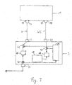
- FIG. 3 A further embodiment of a cleaning and emptying device according to the invention is shown schematically in Fig. 3.
- the cleaning device 2 designed as a mobile unit.
- a connection line WL for the supply of high-pressure Water provided.
- Tank 1 or cleaning device 2 have to corresponding connections 17 and 27, respectively. That under the pressure standing water is thereby from the cleaning device 2 by means of a High pressure pump 28 is provided via the controllable valve 47, wherein as Water supply a water tank 29 is provided.
- the water tank 29 accounts, provided an external water supply is possible.
- a supply connection (not shown) may be provided.
- a vacuum pump 20 is further provided with which generates a vacuum can be.
- this vacuum are from the tank 1 the Sucked off residues and the residue output 34 of the cleaning device 2, for example in an external tank or the drainage channel, derived.
- the cleaning process essentially takes place in this device identical as in the embodiment shown in Fig. 1. Only the Steps S1 and S2 (see FIG. 2) are summarized.
- the water is also at high pressure in the extraction steps S4 and S6; However, it can also be provided that the pressure when feeding the Water in the tank 1 is set lower.
- the cleaning device 2 To be able to determine whether the connection lines V and WL of the Cleaning device 2 are properly connected to the tank 1, are on sensors 13 corresponding to the connections 13 and 17 of the tank are provided, the cleaning device 2 a correct attachment of the connecting lines signal. For example, it can be provided that at missing signal the cleaning process can not be started at all can. In a simple embodiment, these sensors 18 are that a ground connection with a ground cable to the connecting lines, which are preferably designed as tubes can be produced got to. The cleaning device 2 is then signaled that all ground connections are made.
- sensors may be provided which signal whether in the Hibernate all connection lines in their correct rest position, preferably located on the cleaning device 2. This can be appropriate Status displays are provided, which signal per connecting line, whether a correct stowage is given. Corresponding status lights can also be provided for the correct mounting position.
- Drainage tanks of biological sewage treatment plants can be emptied more thoroughly and rinse. In particular, it can be reliably ensured that the tank is constantly emptied.
- An automated process is also possible.
- the invention is preferably used for cleaning residue tanks of organic toilets in passenger trains. Such organic toilets or biological
- sewage treatment plants are also used elsewhere, for example in Toilet trolley at major events or in permanently installed toilets large event centers such as trade fair or concert halls.
- the invention can in principle be used for all types of biological wastewater treatment plants. regardless of the intended use and scope of biological Wastewater treatment plant.
Landscapes
- Engineering & Computer Science (AREA)
- Mechanical Engineering (AREA)
- Cleaning In General (AREA)
- Refuse Collection And Transfer (AREA)
Abstract
Description
- Zuführen einer Flüssigkeit, insbesondere von Wasser, in den Tank zum Aufweichen der Rückstände,
- Zuführen eines unter Hochdruck stehenden Mediums, insbesondere Luft, in den Tank zum Aufwirbeln der Rückstände, und
- Absaugen der aufgeweichten und aufgewirbelten Rückstände aus dem Tank, wobei zumindest zeitweise während des Absaugens und/oder in Absaugpausen in den Tank weitere Flüssigkeit zugeführt wird.
- einer Flüssigkeitszufuhreinrichtung zum Zuführen einer Flüssigkeit, insbesondere von Wasser, in den Tank zum Aufweichen der Rückstände,
- einer Mediumzufuhreinrichtung zum Zuführen eines unter Hochdruck stehenden Mediums, insbesondere Luft, in den Tank zum Aufwirbeln der Rückstände,
- einer Absaugeinrichtung zum Absaugen der aufgeweichten und aufgewirbelten Rückstände aus dem Tank, und
- einer Steuereinrichtung zur Steuerung des Reinigungs- und Entleerungsvorgangs derart, dass zumindest zeitweise während des Absaugens und/oder in Absaugpausen weitere Flüssigkeit von der Flüssigkeitszufuhreinrichtung in den Tank zugeführt wird.
- Fig. 1
- eine schematische Darstellung einer ersten Ausgestaltung der erfindungsgemäßen Vorrichtung,
- Fig. 2
- ein Flussdiagramm des Ablaufs des erfindungsgemäßen Verfahrens und
- Fig. 3
- eine schematische Darstellung einer weiteren Ausgestaltung einer erfindungsgemäßen Vorrichtung.
Claims (13)
- Verfahren zum Reinigen und Entleeren eines mit feststoffartigen Rückständen gefüllten Rückstandtanks einer biologischen Kläranlage mit den Schritten:Zuführen einer Flüssigkeit, insbesondere von Wasser, in den Tank zum Aufweichen der Rückstände,Zuführen eines unter Hochdruck stehenden Mediums, insbesondere Luft, in den Tank zum Aufwirbeln der Rückstände, undAbsaugen der aufgeweichten und aufgewirbelten Rückstände aus dem Tank, wobei zumindest zeitweise während des Absaugens und/oder in Absaugpausen in den Tank weitere Flüssigkeit zugeführt wird.
- Verfahren nach Anspruch 1,
dadurch gekennzeichnet, dass zum Absaugen der aufgeweichten und aufgewirbelten Rückstände in einem ersten Schritt nur Rückstände ohne zusätzliche Flüssigkeitszufuhr in den Tank abgesaugt werden und dass in einem zweiten Schritt während des Absaugens in den Tank weitere Flüssigkeit zugeführt wird, wobei der zweite Schritt mehrfach ausgeführt werden kann. - Verfahren nach einem der vorstehenden Ansprüche,
dadurch gekennzeichnet, dass die zugeführte Flüssigkeitsmenge und die abgesaugte Rückstandsmenge erfasst wird und dass die Zufuhr der Flüssigkeit in den Tank während des Absaugens derart gesteuert wird, dass der Tank nicht überläuft. - Verfahren nach einem der vorstehenden Ansprüche,
dadurch gekennzeichnet, dass die Zufuhr der Flüssigkeit in dem ersten Schritt und die Zufuhr des unter Hochdruck stehenden Mediums in dem zweiten Schritt zumindest zeitweise gleichzeitig erfolgen, insbesondere vollständig gleichzeitig und durch Zufuhr einer unter Hochdruck stehenden Flüssigkeit, insbesondere Wasser, erfolgen. - Verfahren nach einem der vorstehenden Ansprüche,
dadurch gekennzeichnet, dass die abgesaugte Rückstandsmenge erfasst wird, wobei das Erfassungsergebnis dazu verwendet wird, das Verfahren von neuem zu starten, wenn beim Absaugen über einen vorbestimmten Zeitraum nicht eine erste vorbestimmte Rückstandsmenge abgesaugt wird, oder das Verfahren zu beenden, wenn beim Absaugen eine zweite vorbestimmte Rückstandsmenge erreicht wird. - Verfahren nach einem der vorstehenden Ansprüche,
dadurch gekennzeichnet, dass die einzelnen Schritte zeitgesteuert und automatisch ablaufen, wobei die Parameter der Zeitsteuerung an den zu reinigenden und entleerenden Tank anpassbar sind. - Vorrichtung zum Reinigen und Entleeren eines mit feststoffartigen Rückständen gefüllten Rückstandtanks einer biologischen Kläranlage mit:einer Flüssigkeitszufuhreinrichtung zum Zuführen einer Flüssigkeit, insbesondere von Wasser, in den Tank zum Aufweichen der Rückstände,einer Mediumzufuhreinrichtung zum Zuführen eines unter Hochdruck stehenden Mediums, insbesondere Luft, in den Tank zum Aufwirbeln der Rückstände,einer Absaugeinrichtung zum Absaugen der aufgeweichten und aufgewirbelten Rückstände aus dem Tank, undeiner Steuereinrichtung zur Steuerung des Reinigungs- und Entleerungsvorgangs derart, dass zumindest zeitweise während des Absaugens und/oder in Absaugpausen weitere Flüssigkeit von der Flüssigkeitszufuhreinrichtung in den Tank zugeführt wird.
- Vorrichtung nach Anspruch 7,
dadurch gekennzeichnet, dass die Flüssigkeitszufuhreinrichtung und die Mediumzufuhreinrichtung als eine einzige Leitung, insbesondere zum Zuführen einer unter Hochdruck stehenden Flüssigkeit, insbesondere Wasser, ausgestaltet ist. - Vorrichtung nach Anspruch 7 oder 8,
dadurch gekennzeichnet, dass Flüssigkeitsdurchflussmessmittel zum Erfassen der zugeführten Flüssigkeit und Rückstandsdurchflussmessmittel zum Erfassen der abgesaugten Rückstände vorgesehen sind und dass die Steuereinrichtung ausgestaltet ist zur Steuerung der Zufuhr der Flüssigkeit in den Tank während des Absaugens derart, dass der Tank nicht überläuft. - Vorrichtung nach einem der Ansprüche 7 bis 9,
dadurch gekennzeichnet, dass Rückstandsdurchflussmessmittel zum Erfassen der abgesaugten Rückstandsmenge vorgesehen sind und dass die Steuereinrichtung ausgestaltet ist zur Steuerung des Reinigungs- und Entleerungsvorgangs derart, dass das Erfassungsergebnis dazu verwendet wird, das Verfahren von neuem zu starten, wenn beim Absaugen über einen vorbestimmten Zeitraum nicht eine erste vorbestimmte Rückstandsmenge abgesaugt wird, oder das Verfahren zu beenden, wenn beim Absaugen eine zweite vorbestimmte Rückstandsmenge erreicht wird. - Vorrichtung nach einem der Ansprüche 7 bis 10,
dadurch gekennzeichnet, dass die Vorrichtung als mobile Vorrichtung ausgestaltet ist und dass die Flüssigkeitszufuhreinrichtung einen Flüssigkeitsvorratsbehälter und die Absaugeinrichtung eine Vakuumpumpe aufweisen. - Vorrichtung nach einem der Ansprüche 7 bis 11,
dadurch gekennzeichnet, dass die Vorrichtung als stationäre Vorrichtung ausgestaltet ist und dass die Flüssigkeitszufuhreinrichtung einen Flüssigkeitsanschluss zum Anschluss an eine Flüssigkeitszuleitung und die Absaugeinrichtung einen Vakuumanschluss zum Anschluss an eine Vakuumleitung aufweisen. - Vorrichtung nach einem der Ansprüche 7 bis 12,
dadurch gekennzeichnet, dass Sensormittel zur Ermittlung, ob die Flüssigkeitszufuhreinrichtung, die Mediumzufuhreinrichtung und die Absaugeinrichtung mit dem Tank verbunden sind, vorgesehen sind.
Applications Claiming Priority (2)
| Application Number | Priority Date | Filing Date | Title |
|---|---|---|---|
| DE10343243A DE10343243B4 (de) | 2003-09-17 | 2003-09-17 | Verfahren und Vorrichtung zum Spülen und Entleeren eines mit feststoffartigen Rückständen gefüllten Rückstandtanks einer biologischen Kläranlage |
| DE10343243 | 2003-09-17 |
Publications (2)
| Publication Number | Publication Date |
|---|---|
| EP1516682A1 true EP1516682A1 (de) | 2005-03-23 |
| EP1516682B1 EP1516682B1 (de) | 2008-10-22 |
Family
ID=34177814
Family Applications (1)
| Application Number | Title | Priority Date | Filing Date |
|---|---|---|---|
| EP04021191A Expired - Lifetime EP1516682B1 (de) | 2003-09-17 | 2004-09-07 | Verfahren und Vorrichtung zum Spülen und Entleeren eines mit feststoffartigen Rückständen gefüllten Rückstandtanks einer biologischen Kläranlage |
Country Status (3)
| Country | Link |
|---|---|
| EP (1) | EP1516682B1 (de) |
| AT (1) | ATE411853T1 (de) |
| DE (2) | DE10343243B4 (de) |
Families Citing this family (1)
| Publication number | Priority date | Publication date | Assignee | Title |
|---|---|---|---|---|
| EP2364893A1 (de) | 2010-03-12 | 2011-09-14 | Schweizerische Bundesbahnen SBB | Verfahren und Vorrichtung zur Entleerung eines Feststoffbehälters |
Citations (5)
| Publication number | Priority date | Publication date | Assignee | Title |
|---|---|---|---|---|
| US2638224A (en) * | 1947-05-29 | 1953-05-12 | Gorman Rupp Co | Apparatus for cleansing septic tanks |
| US4214705A (en) * | 1978-12-18 | 1980-07-29 | Chemdet Sonic Systems, Inc. | Apparatus for cleaning tanks |
| US4234980A (en) * | 1979-05-16 | 1980-11-25 | Aquatech, Inc. | Apparatus for sewer cleaning and the like |
| US5657782A (en) * | 1996-01-05 | 1997-08-19 | Berning; Robert D. | Septic tank flush |
| JPH10309972A (ja) * | 1997-05-13 | 1998-11-24 | Sanki Tsuuun Kk | 粉体輸送タンク車の粉体タンク室のクリーニング方法と、それに用いるクリーニングプラント |
Family Cites Families (5)
| Publication number | Priority date | Publication date | Assignee | Title |
|---|---|---|---|---|
| DE3333481A1 (de) * | 1983-05-20 | 1984-11-22 | Renate 8700 Würzburg Lietz | Verfahren und vorrichtung zur beseitigung von gemischen fester und fluessiger abfallstoffe |
| US4584726A (en) * | 1984-07-09 | 1986-04-29 | Kaiser Aerospace & Electronics Corp. | Fluid operated waste tank servicing assembly |
| US4550453A (en) * | 1984-08-02 | 1985-11-05 | Marion E. Norman | Compact, portable drain to empty and clean a recreational vehicle holding tank |
| FR2683495B1 (fr) * | 1991-11-12 | 1993-12-31 | Spimat Thp | Systeme mobile de traitement des installations sanitaires d'une rame ferroviaire. |
| DE4434437C2 (de) * | 1994-09-27 | 1996-10-02 | Daimler Benz Aerospace Airbus | Vakuumtoilettensystem in einem Flugzeug |
-
2003
- 2003-09-17 DE DE10343243A patent/DE10343243B4/de not_active Expired - Fee Related
-
2004
- 2004-09-07 EP EP04021191A patent/EP1516682B1/de not_active Expired - Lifetime
- 2004-09-07 DE DE502004008309T patent/DE502004008309D1/de not_active Expired - Lifetime
- 2004-09-07 AT AT04021191T patent/ATE411853T1/de not_active IP Right Cessation
Patent Citations (5)
| Publication number | Priority date | Publication date | Assignee | Title |
|---|---|---|---|---|
| US2638224A (en) * | 1947-05-29 | 1953-05-12 | Gorman Rupp Co | Apparatus for cleansing septic tanks |
| US4214705A (en) * | 1978-12-18 | 1980-07-29 | Chemdet Sonic Systems, Inc. | Apparatus for cleaning tanks |
| US4234980A (en) * | 1979-05-16 | 1980-11-25 | Aquatech, Inc. | Apparatus for sewer cleaning and the like |
| US5657782A (en) * | 1996-01-05 | 1997-08-19 | Berning; Robert D. | Septic tank flush |
| JPH10309972A (ja) * | 1997-05-13 | 1998-11-24 | Sanki Tsuuun Kk | 粉体輸送タンク車の粉体タンク室のクリーニング方法と、それに用いるクリーニングプラント |
Non-Patent Citations (1)
| Title |
|---|
| PATENT ABSTRACTS OF JAPAN vol. 1999, no. 02 26 February 1999 (1999-02-26) * |
Also Published As
| Publication number | Publication date |
|---|---|
| DE10343243B4 (de) | 2007-01-25 |
| DE502004008309D1 (de) | 2008-12-04 |
| ATE411853T1 (de) | 2008-11-15 |
| EP1516682B1 (de) | 2008-10-22 |
| DE10343243A1 (de) | 2005-08-04 |
Similar Documents
| Publication | Publication Date | Title |
|---|---|---|
| EP3209834B1 (de) | Sanitäreinheit mit überwachungseinrichtung | |
| EP1911382B1 (de) | Vorrichtung zur Zubereitung und Ausgabe von Getränken mit Reinigungseinrichtung | |
| AT508458B1 (de) | Vorrichtung und verfahren zum reinigen von abwasserleitungen von unterdrucktoilettenanlagen | |
| EP4146367B1 (de) | Automatisierter durchlasstest für einen filterkorb | |
| DE202009010176U1 (de) | Vakuumtoilette und Steuereinheit zum Steuern eines Betriebs einer Vakuumtoilette | |
| EP2402066A1 (de) | Unterdruckbehälter, System und Verfahren zum Entfernen von Störstoffen aus einer Biogasanlage | |
| EP4179061A1 (de) | Bioreaktorreinigungsanlage mit einem säuretank sowie einer einrichtung zum neutralisieren der säure | |
| EP0873973B1 (de) | Verfahren zum Befüllen eines Trinkwassertanks und Vorrichtung zur Trinkwasserversorgung | |
| DE10204737A1 (de) | Verfahren und Vorrichtung zum Spülen und Reinigen einer Rohrleitung, insbesondere einer Trinkwasserleitung | |
| EP2364893A1 (de) | Verfahren und Vorrichtung zur Entleerung eines Feststoffbehälters | |
| EP1860073A1 (de) | Verfahren zum Betrieb eines Drucklufthebersystems für eine Kleinkläranlage und Drucklufthebersystem | |
| EP4179060A1 (de) | Bioreaktorreinigungsanlage für bioreaktoren in schienenfahrzeugen | |
| DE10343243B4 (de) | Verfahren und Vorrichtung zum Spülen und Entleeren eines mit feststoffartigen Rückständen gefüllten Rückstandtanks einer biologischen Kläranlage | |
| DE2245487C3 (de) | Verfahren und Anordnung zur Probeentnahme von Milch | |
| EP0588778A1 (de) | Anlage zur Reinigung von Waschwasser, insbesondere bei Fahrzeugwaschanlagen | |
| DE4243303C1 (de) | Verfahren zum Reinigen eines Brunnenschachtes | |
| AT3656U2 (de) | Verfahren und vorrichtung zum periodischen durchspülen einer abwasser-rohrleitung | |
| EP4248028B1 (de) | Vakuumtoilette und verfahren zum spülen einer vakuumtoilette | |
| DE202020104037U1 (de) | Bioreaktorreinigungsanlage für Bioreaktoren in Schienenfahrzeugen | |
| DE102013213151A1 (de) | Warmwasserspeicher | |
| DE102019114742A1 (de) | Vorrichtung zum Versorgen eines Geräts mit Wasser und Verfahren zum Versorgen eines Geräts mit Wasser | |
| DE2217094A1 (de) | Geraet zum aufbereiten von petroleumhaltigen abwaessern | |
| DE102018218502B4 (de) | Verfahren zur Erkennung einer fehlerhaften Installation einer Abwasserleitung eines Getränkeautomaten | |
| DE102006010569A1 (de) | Unterdruckabwassereinrichtung | |
| DE102017208981B4 (de) | Dosierungstestvorrichtung, Kombinationseinrichtung und Verfahren zum Testen oder Behandeln eines Dosierungsventils einer Dosierungsvorrichtung |
Legal Events
| Date | Code | Title | Description |
|---|---|---|---|
| PUAI | Public reference made under article 153(3) epc to a published international application that has entered the european phase |
Free format text: ORIGINAL CODE: 0009012 |
|
| AK | Designated contracting states |
Kind code of ref document: A1 Designated state(s): AT BE BG CH CY CZ DE DK EE ES FI FR GB GR HU IE IT LI LU MC NL PL PT RO SE SI SK TR |
|
| AX | Request for extension of the european patent |
Extension state: AL HR LT LV MK |
|
| 17P | Request for examination filed |
Effective date: 20050912 |
|
| AKX | Designation fees paid |
Designated state(s): AT CH DE ES FR LI NL |
|
| 17Q | First examination report despatched |
Effective date: 20051121 |
|
| GRAP | Despatch of communication of intention to grant a patent |
Free format text: ORIGINAL CODE: EPIDOSNIGR1 |
|
| GRAS | Grant fee paid |
Free format text: ORIGINAL CODE: EPIDOSNIGR3 |
|
| GRAA | (expected) grant |
Free format text: ORIGINAL CODE: 0009210 |
|
| AK | Designated contracting states |
Kind code of ref document: B1 Designated state(s): AT CH DE ES FR LI NL |
|
| REG | Reference to a national code |
Ref country code: CH Ref legal event code: NV Representative=s name: E. BLUM & CO. AG PATENT- UND MARKENANWAELTE VSP Ref country code: CH Ref legal event code: EP |
|
| REF | Corresponds to: |
Ref document number: 502004008309 Country of ref document: DE Date of ref document: 20081204 Kind code of ref document: P |
|
| NLV1 | Nl: lapsed or annulled due to failure to fulfill the requirements of art. 29p and 29m of the patents act | ||
| PG25 | Lapsed in a contracting state [announced via postgrant information from national office to epo] |
Ref country code: ES Free format text: LAPSE BECAUSE OF FAILURE TO SUBMIT A TRANSLATION OF THE DESCRIPTION OR TO PAY THE FEE WITHIN THE PRESCRIBED TIME-LIMIT Effective date: 20090202 |
|
| PG25 | Lapsed in a contracting state [announced via postgrant information from national office to epo] |
Ref country code: NL Free format text: LAPSE BECAUSE OF FAILURE TO SUBMIT A TRANSLATION OF THE DESCRIPTION OR TO PAY THE FEE WITHIN THE PRESCRIBED TIME-LIMIT Effective date: 20081022 |
|
| PLBE | No opposition filed within time limit |
Free format text: ORIGINAL CODE: 0009261 |
|
| STAA | Information on the status of an ep patent application or granted ep patent |
Free format text: STATUS: NO OPPOSITION FILED WITHIN TIME LIMIT |
|
| 26N | No opposition filed |
Effective date: 20090723 |
|
| REG | Reference to a national code |
Ref country code: FR Ref legal event code: ST Effective date: 20100531 |
|
| PG25 | Lapsed in a contracting state [announced via postgrant information from national office to epo] |
Ref country code: FR Free format text: LAPSE BECAUSE OF NON-PAYMENT OF DUE FEES Effective date: 20090930 |
|
| PG25 | Lapsed in a contracting state [announced via postgrant information from national office to epo] |
Ref country code: AT Free format text: LAPSE BECAUSE OF NON-PAYMENT OF DUE FEES Effective date: 20090907 |
|
| PGFP | Annual fee paid to national office [announced via postgrant information from national office to epo] |
Ref country code: DE Payment date: 20101104 Year of fee payment: 7 |
|
| PGFP | Annual fee paid to national office [announced via postgrant information from national office to epo] |
Ref country code: CH Payment date: 20111005 Year of fee payment: 8 |
|
| REG | Reference to a national code |
Ref country code: CH Ref legal event code: PL |
|
| PG25 | Lapsed in a contracting state [announced via postgrant information from national office to epo] |
Ref country code: CH Free format text: LAPSE BECAUSE OF NON-PAYMENT OF DUE FEES Effective date: 20120930 Ref country code: LI Free format text: LAPSE BECAUSE OF NON-PAYMENT OF DUE FEES Effective date: 20120930 Ref country code: DE Free format text: LAPSE BECAUSE OF NON-PAYMENT OF DUE FEES Effective date: 20130403 |
|
| REG | Reference to a national code |
Ref country code: DE Ref legal event code: R119 Ref document number: 502004008309 Country of ref document: DE Effective date: 20130403 |