EP1516644B1 - Vorrichtung zum Aufstechen des Septums und Platzieren einer transeptalen Vorrichtung an der linken Seite - Google Patents
Vorrichtung zum Aufstechen des Septums und Platzieren einer transeptalen Vorrichtung an der linken Seite Download PDFInfo
- Publication number
- EP1516644B1 EP1516644B1 EP04292248A EP04292248A EP1516644B1 EP 1516644 B1 EP1516644 B1 EP 1516644B1 EP 04292248 A EP04292248 A EP 04292248A EP 04292248 A EP04292248 A EP 04292248A EP 1516644 B1 EP1516644 B1 EP 1516644B1
- Authority
- EP
- European Patent Office
- Prior art keywords
- mandrel
- piercing
- guide
- septum
- probe
- Prior art date
- Legal status (The legal status is an assumption and is not a legal conclusion. Google has not performed a legal analysis and makes no representation as to the accuracy of the status listed.)
- Expired - Lifetime
Links
- 230000000638 stimulation Effects 0.000 title claims description 6
- 239000000523 sample Substances 0.000 claims description 62
- 238000004873 anchoring Methods 0.000 claims description 16
- 238000013519 translation Methods 0.000 claims description 11
- 210000003361 heart septum Anatomy 0.000 claims description 7
- 230000035515 penetration Effects 0.000 claims description 5
- 238000004891 communication Methods 0.000 claims description 3
- 230000000747 cardiac effect Effects 0.000 claims 1
- 238000005553 drilling Methods 0.000 description 13
- 238000000034 method Methods 0.000 description 11
- KWGRBVOPPLSCSI-WPRPVWTQSA-N (-)-ephedrine Chemical compound CN[C@@H](C)[C@H](O)C1=CC=CC=C1 KWGRBVOPPLSCSI-WPRPVWTQSA-N 0.000 description 7
- 208000031968 Cadaver Diseases 0.000 description 6
- 210000005246 left atrium Anatomy 0.000 description 5
- 210000005245 right atrium Anatomy 0.000 description 5
- 239000008280 blood Substances 0.000 description 4
- 210000004369 blood Anatomy 0.000 description 4
- 230000000694 effects Effects 0.000 description 3
- 238000002399 angioplasty Methods 0.000 description 2
- 210000003748 coronary sinus Anatomy 0.000 description 2
- 238000002224 dissection Methods 0.000 description 2
- 238000002513 implantation Methods 0.000 description 2
- 238000009434 installation Methods 0.000 description 2
- 210000004971 interatrial septum Anatomy 0.000 description 2
- 210000005240 left ventricle Anatomy 0.000 description 2
- 238000005192 partition Methods 0.000 description 2
- 238000010992 reflux Methods 0.000 description 2
- 238000010079 rubber tapping Methods 0.000 description 2
- 208000007536 Thrombosis Diseases 0.000 description 1
- 210000000709 aorta Anatomy 0.000 description 1
- 238000013459 approach Methods 0.000 description 1
- 230000001746 atrial effect Effects 0.000 description 1
- 210000005242 cardiac chamber Anatomy 0.000 description 1
- 239000004020 conductor Substances 0.000 description 1
- 239000000284 extract Substances 0.000 description 1
- 239000004744 fabric Substances 0.000 description 1
- 210000002837 heart atrium Anatomy 0.000 description 1
- 210000005003 heart tissue Anatomy 0.000 description 1
- 239000007943 implant Substances 0.000 description 1
- 238000011835 investigation Methods 0.000 description 1
- 230000014759 maintenance of location Effects 0.000 description 1
- 239000002184 metal Substances 0.000 description 1
- 210000004115 mitral valve Anatomy 0.000 description 1
- 230000002093 peripheral effect Effects 0.000 description 1
- 229920001296 polysiloxane Polymers 0.000 description 1
- 230000000717 retained effect Effects 0.000 description 1
- 210000005241 right ventricle Anatomy 0.000 description 1
- 238000007789 sealing Methods 0.000 description 1
- 230000004936 stimulating effect Effects 0.000 description 1
- 238000001356 surgical procedure Methods 0.000 description 1
- 230000002861 ventricular Effects 0.000 description 1
Images


Classifications
-
- A—HUMAN NECESSITIES
- A61—MEDICAL OR VETERINARY SCIENCE; HYGIENE
- A61M—DEVICES FOR INTRODUCING MEDIA INTO, OR ONTO, THE BODY; DEVICES FOR TRANSDUCING BODY MEDIA OR FOR TAKING MEDIA FROM THE BODY; DEVICES FOR PRODUCING OR ENDING SLEEP OR STUPOR
- A61M25/00—Catheters; Hollow probes
- A61M25/0067—Catheters; Hollow probes characterised by the distal end, e.g. tips
- A61M25/0082—Catheter tip comprising a tool
- A61M25/0084—Catheter tip comprising a tool being one or more injection needles
-
- A—HUMAN NECESSITIES
- A61—MEDICAL OR VETERINARY SCIENCE; HYGIENE
- A61M—DEVICES FOR INTRODUCING MEDIA INTO, OR ONTO, THE BODY; DEVICES FOR TRANSDUCING BODY MEDIA OR FOR TAKING MEDIA FROM THE BODY; DEVICES FOR PRODUCING OR ENDING SLEEP OR STUPOR
- A61M25/00—Catheters; Hollow probes
- A61M25/0067—Catheters; Hollow probes characterised by the distal end, e.g. tips
- A61M25/0082—Catheter tip comprising a tool
- A61M25/0084—Catheter tip comprising a tool being one or more injection needles
- A61M2025/0089—Single injection needle protruding axially, i.e. along the longitudinal axis of the catheter, from the distal tip
-
- A—HUMAN NECESSITIES
- A61—MEDICAL OR VETERINARY SCIENCE; HYGIENE
- A61M—DEVICES FOR INTRODUCING MEDIA INTO, OR ONTO, THE BODY; DEVICES FOR TRANSDUCING BODY MEDIA OR FOR TAKING MEDIA FROM THE BODY; DEVICES FOR PRODUCING OR ENDING SLEEP OR STUPOR
- A61M2210/00—Anatomical parts of the body
- A61M2210/12—Blood circulatory system
- A61M2210/125—Heart
-
- A—HUMAN NECESSITIES
- A61—MEDICAL OR VETERINARY SCIENCE; HYGIENE
- A61N—ELECTROTHERAPY; MAGNETOTHERAPY; RADIATION THERAPY; ULTRASOUND THERAPY
- A61N1/00—Electrotherapy; Circuits therefor
- A61N1/02—Details
- A61N1/04—Electrodes
- A61N1/05—Electrodes for implantation or insertion into the body, e.g. heart electrode
- A61N1/0587—Epicardial electrode systems; Endocardial electrodes piercing the pericardium
Definitions
- the invention relates to a device for piercing the cardiac septum and providing a transseptal device.
- the invention may in particular be used for the placement of a probe in a left cavity, with a view to stimulating this cavity by an "active implantable medical device” as defined by Directive 90/385 / EEC of 20 June 1990 of the Council of European Communities, and more specifically a device such as a pacemaker, defibrillator and / or cardiovertor and / or "multisite” device.
- an active implantable medical device as defined by Directive 90/385 / EEC of 20 June 1990 of the Council of European Communities, and more specifically a device such as a pacemaker, defibrillator and / or cardiovertor and / or “multisite” device.
- the invention is not limited to the installation of stimulation probes. As will be understood, it applies advantageously to any invasive surgical technique requiring the passage of the cardiac septum, for example to carry out clinical investigations in one or the other of the left cavities. It may also be angioplasty procedure, especially for mitral valve valvuloplasty operations.
- transseptal approach involves passing the probe through the interauricular or interventricular septum, or “cardiac septum”, to stimulate the left-atrial and / or ventricular cavity, depending on the configuration and placement of the probe. .
- the US-A-5,190,528 discloses a kit for transseptally introducing a catheter for puncturing blood into the left atrial cavity for recirculation to the arterial circuit via an extracorporeal pump.
- the septum is pierced by a needle protruding from the end of a catheter, which pierces the interatrial septum to then allow the passage of the catheter by advancing the latter on the needle, and then removing the latter.
- the handling of such a device is particularly difficult to avoid false operation, and must be done by an experienced practitioner, under fluoroscopic examination to determine the position and distance of the needle relative to the wall to be perforated.
- the US-A-5,312,341 discloses an improvement in which the transseptal catheter is provided with retention means, for example in the form of an inflatable collar, for holding the catheter in place so that its distal end remains inside the left atrium.
- retention means for example in the form of an inflatable collar
- One of the aims of the invention is to overcome the difficulties of the known techniques, by proposing a piercing kit for the cardiac septum and of setting up a transseptal device which minimizes the invasiveness of this intervention (especially in avoiding multiple punctures of the wall), and which allows safe piercing once the site of intervention on the septum wall has been defined.
- kit of the invention is implemented by techniques comparable to already existing techniques (in particular the installation of a subclavian screw stimulation probe), to which practitioners are honed, and that they will be able to adapt without difficulty for a septum piercing procedure.
- the anchoring means may in particular comprise a helical screw secured to the probe head, the latter being adapted to be rotated from the proximal end of the sheath to allow anchoring of the helical screw by screwing into the fabric. of the septum.
- the drilling guide preferably comprises first stop means for limiting the axial movement of the handling mandrel beyond a predetermined axial position, and / or second abutment means for limiting said additional axial stroke of the piercing mandrel. .
- abutment means may in particular be formed of a narrowing of the diameter of the bore of the probe head cooperating with a bulge of the handling mandrel and / or with a shoulder of the piercing mandrel.
- the abutment means may be formed by tapping the bore of the probe head cooperating with a thread homologous to the handling mandrel and / or the piercing mandrel - which makes it possible to control more finely the advance of the piercing mandrel.
- the piercing guide comprises a pierceable seal capable of closing the bore of the probe body at its outlet in the end face.
- the kit may also comprise a guiding catheter adapted to be inserted into the flexible hollow sheath of the piercing guide, and comprising an internal lumen open at both ends, for successively receiving the piercing mandrel and then the guiding mandrel over the entire length. of the guide catheter and beyond the distal opening thereof into the heart chamber.
- a guiding catheter adapted to be inserted into the flexible hollow sheath of the piercing guide, and comprising an internal lumen open at both ends, for successively receiving the piercing mandrel and then the guiding mandrel over the entire length. of the guide catheter and beyond the distal opening thereof into the heart chamber.
- the kit may then advantageously comprise a removable handle, comprising an internal housing open laterally so as to simultaneously receive the proximal ends of the flexible sheath extending the drill guide, the guide catheter and the piercing mandrel, this inner housing being shaped and dimensioned to secure said proximal ends together in predetermined relative positions, thereby forming a piercing template preventing excessive penetration of the piercing mandrel and / or guide catheter beyond the septum wall after removal of the removable handle and axial depression of the piercing mandrel and guide catheter.
- Figure 1 shows in section the drilling guide of the invention equipped with a handling mandrel in a configuration corresponding to a first phase of the septum piercing operation.
- FIG. 2 is a counterpart of FIG. 1, the piercing guide being equipped with a piercing mandrel for a second phase of the piercing operation.
- Figure 3 is a counterpart of Figure 1, the drill guide being equipped with a guide mandrel for a third phase of the drilling operation.
- Figure 4 shows the guide mandrel of Figure 3 implanted through the wall of the septum, after removal of the piercing guide, for a fourth step of the piercing operation.
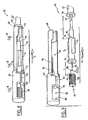
- Figures 5 to 7 are sectional views of an alternative embodiment of the drill guide according to the invention, respectively in an anchoring configuration of the guide, approaching the piercing mandrel and crossing the wall of the septum.
- FIGS. 8 and 9 illustrate a handling tool that is useful for performing the various drilling steps, respectively in an initial configuration and in a subsequent configuration, once the drill guide has been anchored in the septum wall (FIG. in exploded form the different parts of the combination of elements).
- the reference 10 designates the wall of the cardiac septum, for example, in the example described below, the wall separating the cavity 12 of the left atrium from the cavity 14 of the right atrium (note however, this description may be similarly transposed to the portion of the cardiac septum separating the left ventricle from the right ventricle).
- the drilling kit of the invention implements a drilling guide 16 whose structure is comparable to that of a known stimulation probe called “screw probe”, that is to say a probe provided at its distal end with a helical screw having a sharp end, so to allow anchoring in the cardiac tissue at the point of contact with the latter by a rotational movement printed by the practitioner from the proximal end and transmitted to the probe head, and thus the anchor screw, by the connecting sheath the probe head at the proximal end.
- screw probe a known stimulation probe provided at its distal end with a helical screw having a sharp end
- the method of introducing and fixing such a probe is similar to that of conventional probes provided with an anchor screw.
- the probe head 18 has a generally cylindrical shape, and it is provided distal side, on its front end of the anchor screw 20 mentioned above. On the opposite side, the probe head is connected to a hollow flexible sheath 22 (only a portion of which has been shown in the figures) having an internal lumen along its entire length.
- the outer surface 24 of the probe head is a silicone surface.
- the anchoring screw 20 is connected to an inner conductor 26 housed in the lumen of the sheath 22 via the element 18, thus making it possible to collect an electrical signal at the level of the wall of the septum.
- the probe head 18 has an internal axial bore 28 extending to the end face of the probe body and opening at the center thereof in the axis of the helical anchor screw 20.
- the end portion distal 30 of this bore has a smaller diameter than that of the portion 28, so as to locally form a constriction 32, which will be explained below.
- a manipulating mandrel 34 is introduced into the lumen of the sheath 22.
- This manipulating mandrel 34 is of the "profiled mandrel ball” type itself known, that is to say say that its distal end is tapered and ends with a bulge 36 avoiding any risk of drilling or snagging by this end.
- the first phase of the intervention is to set up the handling mandrel 34 in the hollow sheath lumen 22, so as to stiffen the entire probe.
- the diameter of the bulge 36 being greater than that of the axial bore 30, the bulge 36 abuts against the constriction 32, thus preventing the handling mandrel 34 from protruding from the probe.
- the practitioner then introduces the probe head into the cavity 14 of the right atrium until it abuts against the wall 10 of the septum. It then screws the piercing guide 16 on this wall 10 by rotating the probe body 18, and consequently the anchoring screw 20, via the sheath 22 from the proximal end of this wall. last (will be described below, with reference in particular to Figure 6, a tool for performing this maneuver).
- the complete screwing is sensitively detected by the practitioner because of the resistance opposed to the rotation; it is also possible to collect a characteristic electrical signal via the screw 20 to ensure the position of the probe. Once verified, the handling mandrel 34 is removed and replaced by a piercing mandrel.
- FIG. 2 illustrates this piercing mandrel 38, introduced into the piercing guide 16.
- the piercing mandrel 38 has a distal end 40 of reduced diameter, smaller than that of the internal bore 30 of the probe head.
- a shoulder 42 of the piercing mandrel abuts against the internal constriction 32, at the junction of the bore portions 28 and 30, so as to limit the length L from which the pointed distal end 44 of the piercing mandrel 38 emerges beyond the end face of the probe head 18.
- the pointed end 44 remains positioned precisely in the axis of this anchoring screw, which makes it possible to perforate locally and very precisely the septum, without risk of multiple punctures or dissection of the wall by an unexpected rotational movement of the pointed end, as could be the case with the operating techniques implemented so far.
- a variant (not shown) consists in providing the end of the piercing mandrel 38 with a thread cooperating with a tapping formed in the bore 30 to the abutment of the shoulder 42: the septum is then pierced with a relative rotation of the piercing mandrel 38 relative to the piercing guide 16, which provides the correlative advantage of limiting the elongation of the body of the probe under the effect of the stresses resulting from the piercing force of the septum as long as it has not been crossed by the piercing mandrel 38.
- the crossing of the septum can be controlled by image intensifier.
- the piercing mandrel 38 is then removed and replaced by a guide mandrel 46; it should be noted that the blood reflux from the left cavity is minimal during this operation because the hole in the septum is very small.
- FIG. 3 illustrates the configuration with the guiding mandrel 46 introduced into the drilling guide 16 and through the wall 10.
- the guiding mandrel 46 is an angioplasty mandrel of conventional type, that is to say a very thin mandrel comprising a metal core provided at its distal end 48 with a spring 50 whose flexible end avoids any risk of perforation.
- This guide mandrel 46 is introduced over a length allowing its distal end 48 to protrude widely inside the left cavity 12.
- the next phase of the intervention consists, while keeping in place the guide mandrel 46, to remove the drill guide 16 by a reverse rotational movement, to remove the anchor screw 20, and then withdrawal by a translation rear guided by the mandrel 46.
- the final configuration thus obtained is that illustrated in FIG. 4, with the mandrel 46 forming an axial guide from one cavity (right atrium 14) to the other (left atrium 12) through the wall of the septum 10.
- This mandrel 46 can then be used for any operation in itself conventional, including the introduction of a guide catheter threaded on the mandrel 46, possibly via a dilator, over the entire length thereof (technique called “ wireguide “or” OTW “, Over The Wire). Once the guide catheter has been inserted through the septum and opens into the left atrium, the guide mandrel 46 will be extracted from this guide catheter to allow the free passage to a probe that can be implanted in the left atrium. or the left ventricle.
- FIGS. 5 to 7 illustrate an alternative embodiment of the piercing guide 16, in which the distal end of the probe head 18 is closed by a cylindrical tube-shaped cover 52 whose front face 54 comprises a pierceable central region but which , in the initial condition illustrated in FIG. 5, ensures a seal between the internal axial bore 28 of the probe head 18 and the external environment so as to avoid any backward flow of blood into the piercing guide 16.
- the piercing mandrel when it has been substituted for the handling mandrel (configuration illustrated in FIG. 7), can pierce its pointed end with the partition 54, with a reinforced seal at this point, especially when this mandrel piercer itself will be removed to make room for the guide mandrel.
- Figures 5 to 7 are sectional views of an alternative embodiment of the drilling guide according to the invention, respectively in a configuration (i) anchoring the guide, (ii) approaching the piercing mandrel and (iii) ) passing through the wall of the septum by the piercing mandrel combined with a guide catheter.
- the internal axial bore has a slight shoulder 32 (also visible in FIG. 6) acting as an abutment for the ball or the end bulge 36 of the handling mandrel 34.
- the light of the hollow flexible sheath 22 has, as well as the internal axial bore 28, an enlarged diameter with respect to the previous embodiment, so as to allow the introduction not only of the successive mandrels (handling mandrel, piercing mandrel and guide mandrel) but also a guide catheter 56 (see Figures 6 and 7), introduced into the device and through the wall of the septum together with the piercing mandrel.
- FIG. 6 illustrates the configuration of the various elements when the guiding catheter 56 and the piercing mandrel 38, after having been introduced into the sheath 22 by the proximal end thereof, are in the vicinity of the internal axial bore 28.
- the next step is, without changing the position of the guide catheter, to advance the piercing mandrel 38 distally until it pierces through its pointed end 44 the partition 54, with a reinforced sealing at this point so as to avoid any blood reflux in the internal bore 28 of the piercing guide 16.
- the next step is to progress simultaneously in the distal direction the piercing mandrel 38 and the guiding catheter 56, until the latter passes through the wall 10 of the septum and emerges inside the cavity 12.
- the configuration different elements at the end of this step is the one shown in Figure 7.
- the next step (in itself conventional and not illustrated) consists, leaving in place the guide catheter 56, to completely remove the piercing mandrel 38, so that after this withdrawal the guide catheter is found alone in place providing a passage between the cavity 12 and the outside of the patient's body. Through this passage, the surgeon can then introduce the guide mandrel until the latter comes to emerge from the guide catheter into the cavity 12.
- the configuration will be similar to that of Figure 7, but with the guiding mandrel (similar to the guiding mandrel 46 of FIGS. 3 and 4) substituted for the piercing mandrel 38.
- the practitioner extracts the guide catheter. Then it removes the drill guide 16, by a reverse rotation movement, having the effect of unscrewing the anchoring screw, followed by a rearward translation guided by the guide mandrel; the configuration of the different elements during these last two steps will be similar to that illustrated previously in Figures 3 and 4.
- FIG. 8 illustrates the set of different elements, referenced 60, in an initial configuration where the handling tool is subject to the drilling guide
- FIG. 9 illustrates this same set in a configuration of the subsequent step, a once the drill guide anchored in the wall of the septum - this figure 9 also showing in exploded form the various parts of the combination.
- This assembly 60 comprises a removable handle 62, combined with the various elements forming the proximal ends of the flexible sheath 22 extending the drill guide, the guide catheter 56 and the piercing mandrel 38. More specifically, the removable handle 62 comprises a housing internal 64 open laterally to receive the various elements above with a particular relative axial positioning.
- FIG. 8 illustrates the removable handle 62 with these various elements housed in the internal cavity 64
- FIG. 9 shows these same elements in the relative position they occupy just after removal of the removable handle, the latter having been simply radially away.
- the flexible sheath 22 of the drill guide 16 ends proximally by a flange 66 capable of abutting against the distal face 68 of the removable handle 62.
- the guide catheter 56 emerges from the flexible sheath 22 in the proximal direction, where it is extended by an enlarged body 70 terminating proximally by a flange 72, this body being laterally provided with fins 74 to facilitate handling by the practitioner.
- the flange 72 is housed in a homologous recess 76 of the removable handle 78, and there is provided in the latter an opening 78 for the passage of one of the fins (the other fin being turned towards the side opening internal housing 64 of the removable handle).
- the piercing mandrel 38 is terminated distally by an operating knob 80 that can be received in a homologous housing 82 of the removable handle 62.
- the end faces of the operating knob 80 are placed on the proximal side 84 and distal side 86, opposite opposite end faces 88 and 90, respectively, of the cavity 82.
- a longitudinal slot 92 laterally open in the same manner as the inner housing 64, connects the housings 82 and 64 receiving the portion of the piercing mandrel 38 between the operating knob 80 and the flange 72 of the guide catheter 56.
- the assembly is in the configuration illustrated in FIG. 8, where the different elements are held in a given relative position, imposed by the geometry of the cavities of the removable handle 62.
- the axial position of the piercing mandrel 38 and the guide catheter 56, between them and with respect to the drill guide 16, corresponds to that illustrated in FIG. 6, that is to say that the tip 44 of the piercing mandrel 38 does not emerge from the guide catheter 56, and that the latter is set back from the end plane distal to the drill guide 16.
- the piercing mandrel 38 and the guiding catheter 56 are secured in position relative to each other by means of the removable handle 62.
- the next step is to remove the handle 62, simply by a lateral movement (arrow B of Figure 8).
- the next step is to push the button 80 of the piercing mandrel (arrow C of Figure 9), thus allowing the other end to perforate the septum, without changing the position of the guide catheter 56.
- the depth of penetration the piercing mandrel 38 is precisely defined by the dimension L defined between the flange 72 and the face 94 vis-à-vis the operating knob 80, this dimension being defined by the geometry of the removable handle 62 when it housed these two elements.
- the next step is to drive the piercing-guide catheter assembly (arrow D of FIG. 9) into the flexible sheath 22 of the piercing guide, so as to simultaneously advance these two elements to they both emerge beyond the wall of the septum, into the cavity 12 (that is to say, in the position shown in Figure 7).
- the depth of penetration is defined by the dimension L ' defined between the flange 66 of the flexible sheath 22 and an opposite face 96 of the body 70 extending the guide catheter, this dimension being defined by the geometry internal housing of the removable handle 62.
- the removable handle 62 makes it possible to secure between them the various elements (flexible sheath 22 integral with the drill guide 16, guiding catheter 56 and piercing mandrel 38) in predetermined relative positions, thus ensuring a function drilling template preventing excessive penetration of the piercing mandrel and / or the guide catheter inside the cavity 12 after removal of the handle and axial depression of the piercing mandrel and guide catheter.
Landscapes
- Health & Medical Sciences (AREA)
- Life Sciences & Earth Sciences (AREA)
- Biomedical Technology (AREA)
- Pulmonology (AREA)
- Engineering & Computer Science (AREA)
- Anesthesiology (AREA)
- Biophysics (AREA)
- Heart & Thoracic Surgery (AREA)
- Hematology (AREA)
- Animal Behavior & Ethology (AREA)
- General Health & Medical Sciences (AREA)
- Public Health (AREA)
- Veterinary Medicine (AREA)
- Surgical Instruments (AREA)
- Media Introduction/Drainage Providing Device (AREA)
Claims (9)
- Ausrüstung zum Durchstechen der Herzscheidewand und zur Platzierung einer transseptalen Vorrichtung, insbesondere einer Sonde zur Stimulation eines linken Herzraums, dadurch gekennzeichnet, dass sie folgendes umfasst:- eine Stichführung (16) mit einem Sondenkörper mit:einer flexiblen hohlen Hülle (22), die über ihre ganze Länge einen-internen Kanal aufweist und ein nahe gelegenes Ende umfasst, das dazu geeignet ist, einen Dorn aus einer Serie von Dornen aufzunehmen, die nacheinander über dieses Nahe gelegene Ende eingeführt werden, sowie ein entferntes Ende, undeinem Sondenkopf (18, 24), der am entfernten Ende der Hülle angeordnet ist und von einer Seite zur anderen von einer axialen Bohrung (28, 30) durchquert wird, die in Verbindung mit dem internen Kanal der Hülle steht, sowie an der entfernten Seite eine frontale Fläche umfasst, die durch Mittel (20) zur Verankerung an der Wandung der Herzscheidewand (10) verlängert ist;- einen Manipulierdorn (34), der dazu geeignet ist, in den Kanal der Hülle und die Bohrung des Sondenkörpers eingeführt zu werden, und im Verhältnis zur Sonde bis zu einer axialen Position verschiebbar beweglich ist, wo dieser Dorn am entfernten Ende nicht über die frontale Fläche des Sondenkörpers hervorsteht;- einen Stechdorn (38) mit einem spitzen entfernten Ende (44), der dazu geeignet ist, in den Kanal der Hülle und die Bohrung des Sondenkörpers eingeführt zu werden, und im Verhältnis zur Sonde bis zu einer ersten axialen Position, wo dieser Dorn am entfernten Ende nicht über die frontale Fläche des Sondenkörpers hervorsteht, verschiebbar beweglich ist, und dann durch einen zusätzlichen gesteuerten axialen Lauf bis zu einer zweiten Position, wo das spitze entfernte Ende (44) über die frontale Fläche austritt, durch die Verankerungsmittel (20) hindurch, über eine Länge, die wenigstens gleich der lokalen Dicke der Scheidewand (10) ist, um diese so von der einen Seite zur anderen zu durchqueren; und- einen Führungsdorn (46), der dazu geeignet ist, in den Kanal der Hülle und die Bohrung des Sondenkörpers eingeführt zu werden, und im Verhältnis zur Sonde bis zu einer axialen Position verschiebbar beweglich ist, wo dieser Dorn über die frontale Fläche über eine Länge austritt, die wenigstens gleich der lokalen Dicke der Scheidewand ist, um so nach dem Zurückziehen der Stichführung (16) eine axiale Führung von einem Raum zum anderen durch die Scheidewand zu bilden, zur Einführung der transseptalen Vorrichtung.
- Ausrüstung nach Anspruch 1, bei welcher die Verankerungsmittel eine mit dem Sondenkopf (18, 24) verbundene spiralförmige Schraube (20) umfassen, wobei diese dazu geeignet ist, ausgehend von dem nahe gelegenen Ende der Hülle drehend mitgenommen zu werden, um die Verankerung der spiralförmigen Schraube durch Einschrauben in das Gewebe der Scheidewand (10) zu erlauben.
- Ausrüstung nach Anspruch 1, bei welcher die Stichführung (16) erste Anschlagmittel umfasst, um die axiale Bewegung des Manipulierdorns über eine vorbestimmte axiale Position hinaus zu begrenzen.
- Ausrüstung nach Anspruch 1, bei welcher die Stichführung (16) zweite Anschlagmittel umfasst, um den zusätzlichen axialen Lauf des Stechdorns zu begrenzen.
- Ausrüstung nach Anspruch 3 oder nach Anspruch 4, bei welcher die ersten und/oder die zweiten Anschlagmittel aus einer Verengung (32) des Durchmessers der Bohrung (28, 30) des Sondenkopfes gebildet sind, die mit einer Verdickung (36) des Manipulierdorns (34) und/oder mit einer Schulter (42) des Stechdorns (38) zusammenwirkt.
- Ausrüstung nach Anspruch 3 oder nach Anspruch 4, bei welcher die ersten und/oder die zweiten Anschlagmittel ein Innengewinde der Bohrung des Sondenkopfs umfassen, das mit einem entsprechenden Außengewinde des Manipulierdorns und/oder des Stechdorns zusammenwirkt.
- Ausrüstung nach Anspruch 1, bei welcher die Stichführung (16) eine perforierbare Dichtung (52, 56) umfasst, die dazu geeignet ist, die Bohrung des Sondenkörpers an deren Mündung in die frontale Fläche zu verschließen.
- Ausrüstung nach Anspruch 1, weiterhin mit:- einer Katheterführung (56), die dazu geeignet ist, in die flexible hohle Hülle (22) der Stichführung (16) eingeführt zu werden, und einen an seinen beiden Enden offenen Innenkanal umfasst, um nacheinander den Stechdorn (38) und dann den Führungsdorn (46) über die gesamte Länge der Katheterführung und jenseits deren entfernten Öffnung bis in den Herzraum aufzunehmen.
- Ausrüstung nach Anspruch 7, weiterhin mit:- einem abnehmbaren Manipuliergriff (62), der einen inneren Sitz (64) umfasst, welcher seitlich offen ist, um gleichzeitig das nahe gelegene Ende der die Stichführung (16) verlängernden flexiblen Hülle (22), der Katheterführung (56) und des Stechdorns (38) aufzunehmen, wobei dieser innere Sitz (64) so angepasst und dimensioniert ist (L, L'), dass diese nahe gelegenen Enden untereinander auf vorbestimmte relative Positionen festgelegt sind, um so ein Stechwerkzeug auszubilden, das jegliches übermäßiges Eindringen des Stechdorns und/oder der Katheterführung jenseits der Wandung der Scheidewand nach Entfernen des abnehmbaren Griffs (62) und axialem Eindrücken des Stechdorns (38) und der Katheterführung (56) verhindert.
Applications Claiming Priority (2)
| Application Number | Priority Date | Filing Date | Title |
|---|---|---|---|
| FR0311065A FR2859912B1 (fr) | 2003-09-22 | 2003-09-22 | Necessaire de percage du septum cardiaque et de mise en place d'un dispositif transseptal, notamment d'une sonde de stimulation d'une cavite gauche |
| FR0311065 | 2003-09-22 |
Publications (2)
| Publication Number | Publication Date |
|---|---|
| EP1516644A1 EP1516644A1 (de) | 2005-03-23 |
| EP1516644B1 true EP1516644B1 (de) | 2007-11-28 |
Family
ID=34178931
Family Applications (1)
| Application Number | Title | Priority Date | Filing Date |
|---|---|---|---|
| EP04292248A Expired - Lifetime EP1516644B1 (de) | 2003-09-22 | 2004-09-20 | Vorrichtung zum Aufstechen des Septums und Platzieren einer transeptalen Vorrichtung an der linken Seite |
Country Status (5)
| Country | Link |
|---|---|
| US (1) | US7620457B2 (de) |
| EP (1) | EP1516644B1 (de) |
| JP (1) | JP4722441B2 (de) |
| DE (1) | DE602004010338T2 (de) |
| FR (1) | FR2859912B1 (de) |
Families Citing this family (27)
| Publication number | Priority date | Publication date | Assignee | Title |
|---|---|---|---|---|
| US8409219B2 (en) | 2004-06-18 | 2013-04-02 | Medtronic, Inc. | Method and system for placement of electrical lead inside heart |
| US9326756B2 (en) * | 2006-05-17 | 2016-05-03 | St. Jude Medical, Atrial Fibrillation Division, Inc. | Transseptal catheterization assembly and methods |
| US8114110B2 (en) * | 2004-09-22 | 2012-02-14 | St. Jude Medical, Atrial Fibrillation Division, Inc. | Transseptal puncture needle and needle assemblies |
| US7321798B2 (en) * | 2005-03-31 | 2008-01-22 | Medtronic, Inc. | Trans-septal/trans-myocardial ventricular pacing lead |
| US7983765B1 (en) * | 2005-08-19 | 2011-07-19 | Pacesetter, Inc. | Left chamber pressure sensor lead delivery system |
| US7515971B1 (en) * | 2005-09-09 | 2009-04-07 | Pacesetter, Inc. | Left atrial pressure sensor lead |
| EP2626100B1 (de) * | 2006-05-05 | 2016-09-07 | Cathrx Ltd | Elektrischen ableitung fuer modulaire katheteranordnung und herstellungsverfahren |
| US9008795B2 (en) * | 2006-08-04 | 2015-04-14 | Cathrx Ltd | Catheter handle assembly |
| US7846123B2 (en) * | 2007-04-24 | 2010-12-07 | Emory University | Conduit device and system for implanting a conduit device in a tissue wall |
| DE102008040304A1 (de) * | 2008-07-10 | 2010-01-14 | Biotronik Crm Patent Ag | Implantierbare Elektrodenleitung oder Elektrodenleitungsanordnung |
| DE102009030340B4 (de) * | 2009-06-25 | 2011-12-01 | Peter Osypka | Elektrodenanordnung mit einer Stimulationselektrode für den linken Ventrikel |
| EP2327366B1 (de) | 2009-11-30 | 2012-03-14 | Sorin CRM SAS | Besteck zum Bohren des Herzseptums und Implantieren einer transseptalen Sonde, insbesondere einer Sonde zum Feststellen/Stimulieren einer Vertiefung links vom Herzen |
| EP2384784B1 (de) | 2010-05-05 | 2012-09-26 | Sorin CRM SAS | Einheit zur endokavitären Stimulation/Defibrillation des linken Herzventrikels |
| US9072872B2 (en) * | 2010-10-29 | 2015-07-07 | Medtronic, Inc. | Telescoping catheter delivery system for left heart endocardial device placement |
| US10179009B2 (en) | 2012-08-07 | 2019-01-15 | Ahmad Abdul-Karim | Needleless transseptal access device and methods |
| EP2719424B1 (de) * | 2012-10-12 | 2015-04-08 | Sorin CRM SAS | Intraseptale Sonde zur Stimulation des linken Ventrikels |
| EP2818201B1 (de) | 2013-06-24 | 2016-07-20 | Sorin CRM SAS | Intrakardiale Kapsel und entsprechendes Zubehörteil zur Implantation in situ über den femoralen Weg |
| EP2818202B1 (de) | 2013-06-24 | 2016-04-13 | Sorin CRM SAS | Anschlusssystem zwischen einer medizinischen Vorrichtung und ihrem Implantationszubehörteil in situ |
| US10492829B2 (en) * | 2014-08-06 | 2019-12-03 | Boston Scientific Scimed, Inc. | Reusable delivery devices |
| US10786302B2 (en) | 2015-10-09 | 2020-09-29 | Medtronic, Inc. | Method for closure and ablation of atrial appendage |
| US10881868B2 (en) | 2016-05-24 | 2021-01-05 | Sorin Crm Sas | Torque limiting mechanism between a medical device and its implantation accessory |
| CN106510813B (zh) * | 2016-12-09 | 2023-05-26 | 成都五义医疗科技有限公司 | 一种可局部变形的无刀穿刺针 |
| CN109700508A (zh) * | 2018-12-29 | 2019-05-03 | 先健科技(深圳)有限公司 | 穿刺组件及具有其的穿刺系统 |
| CN114681018B (zh) * | 2020-12-30 | 2024-07-02 | 杭州德晋医疗科技有限公司 | 一种心内膜注射装置及心内膜注射系统 |
| CN113456990B (zh) * | 2021-07-30 | 2025-04-04 | 北京迈迪斯医疗技术有限公司 | 介入导管器械 |
| US20250041594A1 (en) * | 2021-12-03 | 2025-02-06 | Biotronik Se & Co. Kg | Sheath for Implanting an Electrode in the Septum of a Human Heart and Method for Implanting an Electrode in the Septum of a Human Heart |
| CN118236621B (zh) * | 2024-05-29 | 2024-07-23 | 首都医科大学宣武医院 | 一种神经电刺激组件 |
Family Cites Families (13)
| Publication number | Priority date | Publication date | Assignee | Title |
|---|---|---|---|---|
| FR2365351A1 (fr) * | 1976-09-24 | 1978-04-21 | Benhaim Jean | Sonde pour interruption non chirurgicale du faisceau de his chez l'homme |
| US4790825A (en) * | 1986-09-05 | 1988-12-13 | Electro Catheter Corporation | Closed chest cannulation method and device for atrial-major artery bypass |
| JPH0385179A (ja) * | 1989-08-30 | 1991-04-10 | Sumitomo Bakelite Co Ltd | 医療用バルーンカテーテル |
| US5190528A (en) * | 1990-10-19 | 1993-03-02 | Boston University | Percutaneous transseptal left atrial cannulation system |
| US5312341A (en) * | 1992-08-14 | 1994-05-17 | Wayne State University | Retaining apparatus and procedure for transseptal catheterization |
| US5447533A (en) * | 1992-09-03 | 1995-09-05 | Pacesetter, Inc. | Implantable stimulation lead having an advanceable therapeutic drug delivery system |
| US5487385A (en) * | 1993-12-03 | 1996-01-30 | Avitall; Boaz | Atrial mapping and ablation catheter system |
| US5873864A (en) * | 1995-12-18 | 1999-02-23 | Luther Medical Products, Inc. | Catheter with beveled needle tip |
| US6416510B1 (en) * | 1997-03-13 | 2002-07-09 | Biocardia, Inc. | Drug delivery catheters that attach to tissue and methods for their use |
| US6547787B1 (en) * | 1997-03-13 | 2003-04-15 | Biocardia, Inc. | Drug delivery catheters that attach to tissue and methods for their use |
| JP4493126B2 (ja) * | 1999-08-20 | 2010-06-30 | オリンパス株式会社 | 内視鏡用注射針 |
| US6970748B2 (en) * | 2002-04-04 | 2005-11-29 | Cardiac Pacemakers, Inc. | Method of using finishing wire with large ball-nose tip |
| US7103418B2 (en) * | 2002-10-02 | 2006-09-05 | Medtronic, Inc. | Active fluid delivery catheter |
-
2003
- 2003-09-22 FR FR0311065A patent/FR2859912B1/fr not_active Expired - Fee Related
-
2004
- 2004-09-20 EP EP04292248A patent/EP1516644B1/de not_active Expired - Lifetime
- 2004-09-20 DE DE602004010338T patent/DE602004010338T2/de not_active Expired - Lifetime
- 2004-09-22 US US10/947,649 patent/US7620457B2/en not_active Expired - Lifetime
- 2004-09-22 JP JP2004276225A patent/JP4722441B2/ja not_active Expired - Lifetime
Also Published As
| Publication number | Publication date |
|---|---|
| DE602004010338T2 (de) | 2008-10-09 |
| JP4722441B2 (ja) | 2011-07-13 |
| DE602004010338D1 (de) | 2008-01-10 |
| US7620457B2 (en) | 2009-11-17 |
| EP1516644A1 (de) | 2005-03-23 |
| FR2859912B1 (fr) | 2005-11-18 |
| JP2005118548A (ja) | 2005-05-12 |
| FR2859912A1 (fr) | 2005-03-25 |
| US20050085883A1 (en) | 2005-04-21 |
Similar Documents
| Publication | Publication Date | Title |
|---|---|---|
| FR2859912A1 (fr) | Necessaire de percage du septum cardiaque et de mise en place d'un dispositif transseptal, notamment d'une sonde de stimulation d'une cavite gauche | |
| EP2327366B1 (de) | Besteck zum Bohren des Herzseptums und Implantieren einer transseptalen Sonde, insbesondere einer Sonde zum Feststellen/Stimulieren einer Vertiefung links vom Herzen | |
| EP2818201B1 (de) | Intrakardiale Kapsel und entsprechendes Zubehörteil zur Implantation in situ über den femoralen Weg | |
| EP2818202B1 (de) | Anschlusssystem zwischen einer medizinischen Vorrichtung und ihrem Implantationszubehörteil in situ | |
| EP1155710B1 (de) | Vorrichtung zum Implantieren von einer Herzstimulationsleitung in Koronargefässen | |
| EP2929910B1 (de) | Intrakardiale Kapsel und ihr Zubehör für die Explantation | |
| EP0993840B1 (de) | In Koronarvenen implantierbare Leitung zur Stimulation eines linken Herzhohlraumes | |
| EP2394695B1 (de) | Autonome intrakardiale Kapsel, und entsprechendes Implantationszubehör | |
| EP2246091B1 (de) | Intrakardialer Sensor zur Stimulation oder Defibrillation mit zurückziehbarer Schraube | |
| EP2457612B1 (de) | Instrumentarium zum Stimulieren/Defibrillieren des linken Ventrikels auf endokavitärem Weg oder über eine Koronarvene | |
| EP2719424B1 (de) | Intraseptale Sonde zur Stimulation des linken Ventrikels | |
| EP3069754B1 (de) | In-situ-implantationszubehör für autonome intrakardiale kapsel | |
| EP0207438A1 (de) | Sonde für eine in den Körper einzupflanzende Elektrode | |
| EP2081504A2 (de) | Chirurgischer führungsdraht mit mehreren nadeln für ein hohlorgan und entsprechendes system | |
| EP2384784A1 (de) | Einheit zur endokavitären Stimulation/Defibrillation des linken Herzventrikels | |
| FR2757773A1 (fr) | Sonde pour dispositif medical a implanter dans le coeur humain pour la stimulation et la detection auriculaire et ventriculaire du coeur | |
| EP2308550B1 (de) | Epikardiale Sonde zur Stimulation/Defibrillation mit einer Schraube, die mit Hilfe eines Führungskatheters in den perikardialen Raum implantiert werden kann | |
| EP2275170B1 (de) | Implantateinheit zum Einsetzen in das Koronarvenennetz, die eine Stimulationssonde mit Verankerungsschraube umfasst | |
| EP2392377A1 (de) | Werkzeug zum Einführen eines Katheters | |
| EP3006082B1 (de) | Zubehör zur entfernung einer implantierten intrakorporalen kapsel | |
| EP3389773B1 (de) | Kommunikationsverstärkungsvorrichtung mit halteelementen für eine implantierbare kapsel | |
| EP3639884B1 (de) | Kupplungssystem zwischen einem leadless herzimplantat und einem zugehörigen implantationswerkzeug | |
| FR2840222A1 (fr) | Accessoire de mise en place d'un catheter-guide | |
| EP0740943A1 (de) | Vorrichtung zur Handhabung und zum Einsetzen von einer Elektrode in einem Herzschrittmachergerät |
Legal Events
| Date | Code | Title | Description |
|---|---|---|---|
| PUAI | Public reference made under article 153(3) epc to a published international application that has entered the european phase |
Free format text: ORIGINAL CODE: 0009012 |
|
| AK | Designated contracting states |
Kind code of ref document: A1 Designated state(s): AT BE BG CH CY CZ DE DK EE ES FI FR GB GR HU IE IT LI LU MC NL PL PT RO SE SI SK TR |
|
| AX | Request for extension of the european patent |
Extension state: AL HR LT LV MK |
|
| 17P | Request for examination filed |
Effective date: 20050907 |
|
| AKX | Designation fees paid |
Designated state(s): AT BE BG CH CY CZ DE DK EE ES FI FR GB GR HU IE IT LI LU MC NL PL PT RO SE SI SK TR |
|
| GRAP | Despatch of communication of intention to grant a patent |
Free format text: ORIGINAL CODE: EPIDOSNIGR1 |
|
| GRAS | Grant fee paid |
Free format text: ORIGINAL CODE: EPIDOSNIGR3 |
|
| GRAA | (expected) grant |
Free format text: ORIGINAL CODE: 0009210 |
|
| AK | Designated contracting states |
Kind code of ref document: B1 Designated state(s): AT BE BG CH CY CZ DE DK EE ES FI FR GB GR HU IE IT LI LU MC NL PL PT RO SE SI SK TR |
|
| REG | Reference to a national code |
Ref country code: GB Ref legal event code: FG4D Free format text: NOT ENGLISH |
|
| REG | Reference to a national code |
Ref country code: IE Ref legal event code: FG4D Free format text: LANGUAGE OF EP DOCUMENT: FRENCH |
|
| REG | Reference to a national code |
Ref country code: CH Ref legal event code: EP |
|
| REF | Corresponds to: |
Ref document number: 602004010338 Country of ref document: DE Date of ref document: 20080110 Kind code of ref document: P |
|
| REG | Reference to a national code |
Ref country code: SE Ref legal event code: TRGR |
|
| GBT | Gb: translation of ep patent filed (gb section 77(6)(a)/1977) |
Effective date: 20080228 |
|
| PG25 | Lapsed in a contracting state [announced via postgrant information from national office to epo] |
Ref country code: ES Free format text: LAPSE BECAUSE OF FAILURE TO SUBMIT A TRANSLATION OF THE DESCRIPTION OR TO PAY THE FEE WITHIN THE PRESCRIBED TIME-LIMIT Effective date: 20080311 Ref country code: NL Free format text: LAPSE BECAUSE OF FAILURE TO SUBMIT A TRANSLATION OF THE DESCRIPTION OR TO PAY THE FEE WITHIN THE PRESCRIBED TIME-LIMIT Effective date: 20071128 |
|
| NLV1 | Nl: lapsed or annulled due to failure to fulfill the requirements of art. 29p and 29m of the patents act | ||
| PG25 | Lapsed in a contracting state [announced via postgrant information from national office to epo] |
Ref country code: SI Free format text: LAPSE BECAUSE OF FAILURE TO SUBMIT A TRANSLATION OF THE DESCRIPTION OR TO PAY THE FEE WITHIN THE PRESCRIBED TIME-LIMIT Effective date: 20071128 Ref country code: PL Free format text: LAPSE BECAUSE OF FAILURE TO SUBMIT A TRANSLATION OF THE DESCRIPTION OR TO PAY THE FEE WITHIN THE PRESCRIBED TIME-LIMIT Effective date: 20071128 Ref country code: BG Free format text: LAPSE BECAUSE OF FAILURE TO SUBMIT A TRANSLATION OF THE DESCRIPTION OR TO PAY THE FEE WITHIN THE PRESCRIBED TIME-LIMIT Effective date: 20080228 Ref country code: FI Free format text: LAPSE BECAUSE OF FAILURE TO SUBMIT A TRANSLATION OF THE DESCRIPTION OR TO PAY THE FEE WITHIN THE PRESCRIBED TIME-LIMIT Effective date: 20071128 |
|
| PG25 | Lapsed in a contracting state [announced via postgrant information from national office to epo] |
Ref country code: AT Free format text: LAPSE BECAUSE OF FAILURE TO SUBMIT A TRANSLATION OF THE DESCRIPTION OR TO PAY THE FEE WITHIN THE PRESCRIBED TIME-LIMIT Effective date: 20071128 |
|
| PG25 | Lapsed in a contracting state [announced via postgrant information from national office to epo] |
Ref country code: CZ Free format text: LAPSE BECAUSE OF FAILURE TO SUBMIT A TRANSLATION OF THE DESCRIPTION OR TO PAY THE FEE WITHIN THE PRESCRIBED TIME-LIMIT Effective date: 20071128 Ref country code: DK Free format text: LAPSE BECAUSE OF FAILURE TO SUBMIT A TRANSLATION OF THE DESCRIPTION OR TO PAY THE FEE WITHIN THE PRESCRIBED TIME-LIMIT Effective date: 20071128 |
|
| PG25 | Lapsed in a contracting state [announced via postgrant information from national office to epo] |
Ref country code: SK Free format text: LAPSE BECAUSE OF FAILURE TO SUBMIT A TRANSLATION OF THE DESCRIPTION OR TO PAY THE FEE WITHIN THE PRESCRIBED TIME-LIMIT Effective date: 20071128 Ref country code: RO Free format text: LAPSE BECAUSE OF FAILURE TO SUBMIT A TRANSLATION OF THE DESCRIPTION OR TO PAY THE FEE WITHIN THE PRESCRIBED TIME-LIMIT Effective date: 20071128 |
|
| PG25 | Lapsed in a contracting state [announced via postgrant information from national office to epo] |
Ref country code: PT Free format text: LAPSE BECAUSE OF FAILURE TO SUBMIT A TRANSLATION OF THE DESCRIPTION OR TO PAY THE FEE WITHIN THE PRESCRIBED TIME-LIMIT Effective date: 20080428 |
|
| PLBE | No opposition filed within time limit |
Free format text: ORIGINAL CODE: 0009261 |
|
| STAA | Information on the status of an ep patent application or granted ep patent |
Free format text: STATUS: NO OPPOSITION FILED WITHIN TIME LIMIT |
|
| 26N | No opposition filed |
Effective date: 20080829 |
|
| PG25 | Lapsed in a contracting state [announced via postgrant information from national office to epo] |
Ref country code: GR Free format text: LAPSE BECAUSE OF FAILURE TO SUBMIT A TRANSLATION OF THE DESCRIPTION OR TO PAY THE FEE WITHIN THE PRESCRIBED TIME-LIMIT Effective date: 20080229 |
|
| BERE | Be: lapsed |
Owner name: ELA MEDICAL Effective date: 20080930 |
|
| PG25 | Lapsed in a contracting state [announced via postgrant information from national office to epo] |
Ref country code: EE Free format text: LAPSE BECAUSE OF FAILURE TO SUBMIT A TRANSLATION OF THE DESCRIPTION OR TO PAY THE FEE WITHIN THE PRESCRIBED TIME-LIMIT Effective date: 20071128 Ref country code: MC Free format text: LAPSE BECAUSE OF NON-PAYMENT OF DUE FEES Effective date: 20080930 |
|
| REG | Reference to a national code |
Ref country code: CH Ref legal event code: PL |
|
| PG25 | Lapsed in a contracting state [announced via postgrant information from national office to epo] |
Ref country code: BE Free format text: LAPSE BECAUSE OF NON-PAYMENT OF DUE FEES Effective date: 20080930 Ref country code: CY Free format text: LAPSE BECAUSE OF FAILURE TO SUBMIT A TRANSLATION OF THE DESCRIPTION OR TO PAY THE FEE WITHIN THE PRESCRIBED TIME-LIMIT Effective date: 20071128 |
|
| PG25 | Lapsed in a contracting state [announced via postgrant information from national office to epo] |
Ref country code: CH Free format text: LAPSE BECAUSE OF NON-PAYMENT OF DUE FEES Effective date: 20080930 Ref country code: LI Free format text: LAPSE BECAUSE OF NON-PAYMENT OF DUE FEES Effective date: 20080930 |
|
| PG25 | Lapsed in a contracting state [announced via postgrant information from national office to epo] |
Ref country code: LU Free format text: LAPSE BECAUSE OF NON-PAYMENT OF DUE FEES Effective date: 20080920 Ref country code: HU Free format text: LAPSE BECAUSE OF FAILURE TO SUBMIT A TRANSLATION OF THE DESCRIPTION OR TO PAY THE FEE WITHIN THE PRESCRIBED TIME-LIMIT Effective date: 20080529 |
|
| PG25 | Lapsed in a contracting state [announced via postgrant information from national office to epo] |
Ref country code: TR Free format text: LAPSE BECAUSE OF FAILURE TO SUBMIT A TRANSLATION OF THE DESCRIPTION OR TO PAY THE FEE WITHIN THE PRESCRIBED TIME-LIMIT Effective date: 20071128 |
|
| PGFP | Annual fee paid to national office [announced via postgrant information from national office to epo] |
Ref country code: SE Payment date: 20120911 Year of fee payment: 9 Ref country code: IE Payment date: 20120912 Year of fee payment: 9 |
|
| REG | Reference to a national code |
Ref country code: SE Ref legal event code: EUG |
|
| PG25 | Lapsed in a contracting state [announced via postgrant information from national office to epo] |
Ref country code: SE Free format text: LAPSE BECAUSE OF NON-PAYMENT OF DUE FEES Effective date: 20130921 |
|
| REG | Reference to a national code |
Ref country code: IE Ref legal event code: MM4A |
|
| PG25 | Lapsed in a contracting state [announced via postgrant information from national office to epo] |
Ref country code: IE Free format text: LAPSE BECAUSE OF NON-PAYMENT OF DUE FEES Effective date: 20130920 |
|
| REG | Reference to a national code |
Ref country code: FR Ref legal event code: PLFP Year of fee payment: 13 |
|
| REG | Reference to a national code |
Ref country code: FR Ref legal event code: PLFP Year of fee payment: 14 |
|
| REG | Reference to a national code |
Ref country code: FR Ref legal event code: PLFP Year of fee payment: 15 |
|
| PGFP | Annual fee paid to national office [announced via postgrant information from national office to epo] |
Ref country code: IT Payment date: 20210811 Year of fee payment: 18 Ref country code: FR Payment date: 20210812 Year of fee payment: 18 |
|
| PGFP | Annual fee paid to national office [announced via postgrant information from national office to epo] |
Ref country code: DE Payment date: 20210810 Year of fee payment: 18 Ref country code: GB Payment date: 20210811 Year of fee payment: 18 |
|
| REG | Reference to a national code |
Ref country code: DE Ref legal event code: R119 Ref document number: 602004010338 Country of ref document: DE |
|
| GBPC | Gb: european patent ceased through non-payment of renewal fee |
Effective date: 20220920 |
|
| PG25 | Lapsed in a contracting state [announced via postgrant information from national office to epo] |
Ref country code: FR Free format text: LAPSE BECAUSE OF NON-PAYMENT OF DUE FEES Effective date: 20220930 Ref country code: DE Free format text: LAPSE BECAUSE OF NON-PAYMENT OF DUE FEES Effective date: 20230401 |
|
| P01 | Opt-out of the competence of the unified patent court (upc) registered |
Effective date: 20230714 |
|
| PG25 | Lapsed in a contracting state [announced via postgrant information from national office to epo] |
Ref country code: IT Free format text: LAPSE BECAUSE OF NON-PAYMENT OF DUE FEES Effective date: 20220920 Ref country code: GB Free format text: LAPSE BECAUSE OF NON-PAYMENT OF DUE FEES Effective date: 20220920 |