EP1516505B1 - Signalwegdetektion für drahtlose netzwerke mit zwischenverstärkern - Google Patents
Signalwegdetektion für drahtlose netzwerke mit zwischenverstärkern Download PDFInfo
- Publication number
- EP1516505B1 EP1516505B1 EP02765154A EP02765154A EP1516505B1 EP 1516505 B1 EP1516505 B1 EP 1516505B1 EP 02765154 A EP02765154 A EP 02765154A EP 02765154 A EP02765154 A EP 02765154A EP 1516505 B1 EP1516505 B1 EP 1516505B1
- Authority
- EP
- European Patent Office
- Prior art keywords
- repeater
- network element
- remote station
- donor
- distance
- Prior art date
- Legal status (The legal status is an assumption and is not a legal conclusion. Google has not performed a legal analysis and makes no representation as to the accuracy of the status listed.)
- Expired - Lifetime
Links
- 238000001514 detection method Methods 0.000 title 1
- 238000000034 method Methods 0.000 claims abstract description 42
- 238000005259 measurement Methods 0.000 claims description 47
- 238000004590 computer program Methods 0.000 claims 1
- 238000004364 calculation method Methods 0.000 description 39
- 238000004422 calculation algorithm Methods 0.000 description 20
- 238000012986 modification Methods 0.000 description 6
- 230000004048 modification Effects 0.000 description 6
- 230000001413 cellular effect Effects 0.000 description 3
- 238000007781 pre-processing Methods 0.000 description 3
- 230000008094 contradictory effect Effects 0.000 description 2
- 238000010295 mobile communication Methods 0.000 description 2
- 101150080339 BTS1 gene Proteins 0.000 description 1
- 230000005540 biological transmission Effects 0.000 description 1
- 238000004891 communication Methods 0.000 description 1
- 230000001934 delay Effects 0.000 description 1
- 230000000694 effects Effects 0.000 description 1
Images

Classifications
-
- H—ELECTRICITY
- H04—ELECTRIC COMMUNICATION TECHNIQUE
- H04W—WIRELESS COMMUNICATION NETWORKS
- H04W64/00—Locating users or terminals or network equipment for network management purposes, e.g. mobility management
-
- G—PHYSICS
- G01—MEASURING; TESTING
- G01S—RADIO DIRECTION-FINDING; RADIO NAVIGATION; DETERMINING DISTANCE OR VELOCITY BY USE OF RADIO WAVES; LOCATING OR PRESENCE-DETECTING BY USE OF THE REFLECTION OR RERADIATION OF RADIO WAVES; ANALOGOUS ARRANGEMENTS USING OTHER WAVES
- G01S5/00—Position-fixing by co-ordinating two or more direction or position line determinations; Position-fixing by co-ordinating two or more distance determinations
- G01S5/02—Position-fixing by co-ordinating two or more direction or position line determinations; Position-fixing by co-ordinating two or more distance determinations using radio waves
-
- H—ELECTRICITY
- H04—ELECTRIC COMMUNICATION TECHNIQUE
- H04B—TRANSMISSION
- H04B7/00—Radio transmission systems, i.e. using radiation field
- H04B7/24—Radio transmission systems, i.e. using radiation field for communication between two or more posts
- H04B7/26—Radio transmission systems, i.e. using radiation field for communication between two or more posts at least one of which is mobile
- H04B7/2603—Arrangements for wireless physical layer control
- H04B7/2606—Arrangements for base station coverage control, e.g. by using relays in tunnels
-
- H—ELECTRICITY
- H04—ELECTRIC COMMUNICATION TECHNIQUE
- H04W—WIRELESS COMMUNICATION NETWORKS
- H04W16/00—Network planning, e.g. coverage or traffic planning tools; Network deployment, e.g. resource partitioning or cells structures
- H04W16/24—Cell structures
- H04W16/26—Cell enhancers or enhancement, e.g. for tunnels, building shadow
Definitions
- the present invention relates to a technique for determining the signal path of a signal transmitted in a wireless network where there is a possibility of repeaters existing in the signal path, and particularly but not exclusivly to a technique for determining the location of a mobile station in the network in dependence on said path determination.
- Networks using repeaters for re-transmision of information are well-known.
- wireless networks such as cellular wireless networks
- the radio signal transmitted by a base transceiver station is received by a repeater and is re-transmitted by the repeater.
- a base transceiver station having a repeater associated there with is known as a donor base transceiver station.
- a donor base transceiver station may be associated with a plurality of repeaters.
- the existence of the repeaters in the cellular network leads to problems for a mobile station (MS) location calculation utilizing the network information (such as base transceiver station (BTS) coordinates).
- MS mobile station
- BTS base transceiver station
- the signals obtained by the MS give no indication as to whether they are from the donor BTS or an associated repeater. As such, reliable and accurate determination of the MS location based on such measurements on signals is difficult. Whilst the unit calculating the MS location knows the location of the donor BTS and associated repeaters, it does not know from which one the measurements were obtained.
- WO-A-01/99444 by Durrant et al discloses a data repeater system that is added to a wireless communications network.
- the data repeater system includes a signal tagging means which adds a unique electronic signature to the repeated signal.
- a time of arrival measurement and recovered signal tag are processed at a mobile location centre to determine the position of the transmitter.
- a method of determining the path of a signal between a donor network element and a remote station, the donor network element being associated with at least one repeater comprising the steps of: receiving at the remote station a plurality of signals associated with a plurality of network elements; calculating an estimate of the distance between the remote station and each network element, based on the received plurality of signals, including an estimate of the distance between the remote station and each repeater associated with the donor network element; determining the one of said estimates of the distance between the remote station and the donor network element and the distance between the remote station and the at least one associated repeater which most closely approximates to the distance between the other network elements and the remote station; and selecting that donor network element/repeater to be the source of the signal.
- the step of calculating an estimate of the distance between the remote station and each network element preferably comprises: selecting each one of the donor network elements and at least one repeater in turn as the source of the signal; and performing said calculating step for only the selected one of the donor network element and at least one repeater.
- the step of calculating the estimate of the distance preferably includes estimating the location of the remote station and thereby estimating an actual distance between each donor network element/repeater and the remote station.
- the step of calculating the estimate of the distance preferably includes measuring physical quantities at the remote station, and thereby estimating a model distance between each network element/repeater and the remote station.
- the measured physical quantity preferably includes the measurement, at the remote station, of one or all of.: a time delay in a received signal; attenuation in a received signal or received signal strength.
- the step of estimating the actual distances preferably further comprises summing the estimated actual distances.
- the step of estimating the model distances preferably further comprises summing the model distances.
- the method may further include calculating a scale factor in dependence on the summed actual and model distances.
- the scale factor may be determined to adapt the scaled sums to be equal.
- the scale factor may be determined by dividing the summed actual estimates by the summed model estimates.
- the model distances estimates may be modified in dependence on said scale factor to produce a set of modified model distances.
- the model distances may be scaled by the scaling factor to produce the modified model distances.
- the method may further include calculating a difference value for each donor network element and at least one repeater by summing the difference between each estimate and each modified model estimate obtained for each respective donor network element and at least one repeater.
- the signal may be determined to be transmitted from the donor network element or at least one repeater having the lowest difference value.
- a plurality of signals may be received from a donor network element, wherein all steps are repeated for each such signal to determine a source of each signal.
- the method may further comprise the step of calculating the location of the remote station in dependence on the determined source of the signal.
- the remote station may be a mobile station and the donor network element is a donor base station.
- a network device adapted to determine the path of a signal between a donor network element and a remote station, the donor network element being associated with at least one repeater, comprising means for calculating an estimate of the distance between the remote station and each network element, including an estimate of the distance between the remote station and each repeater associated with the donor network element, based on a plurality of signals received at a mobile station; means for determining the one of said estimates of the distance between the remote station and the donor network element and the distance between the remote station and the at least one associated repeater which most closely approximates to the distance between the other network elements and the remote station; and means for selecting that donor network element/repeater to be the source of the signal.
- the remote station may be a mobile station and the network element may be a base station.
- the means for calculating an estimate of the distance between the remote station and each network element may include: means for selecting each one of the donor network elements and at least one repeater in turn as the source of the signal; and means for performing said calculating step for only the selected one of the donor network element and at least one repeater.
- the means for calculating the estimate of the distance may include means for estimating the location of the remote station and thereby estimating an actual distance between each donor network element/repeater and the remote station.
- the means for calculating the estimate of the distance may include means for measuring physical quantities at the remote station, and thereby estimating a model distance between each network element/repeater and the remote station.
- the measured physical quantity may include the measurement, at the remote station, of one or all of: a time delay in a received signal; attenuation in a received signal or received signal strength.
- the means for estimating the actual distances may further comprise means for summing the estimated actual distances.
- the means for estimating the model distances may further comprise means for summing the model distances.
- the network device may further include means for calculating a scale factor in dependence on the summed actual and model distances.
- the means for calculating the scale factor may be adapted to convert the scaled sums to be equal.
- the scale factor may be determined by dividing the summed actual estimates by the summed model estimates.
- the model distances estimates may be modified in dependence on said scale factor to produce a set of modified model distances.
- the model distances may be scaled by the scaling factor to produce the modified model distances.
- the network device may further include means for calculating a difference value for each donor network element and at least one repeater, including a summer for summing the difference between each estimate and each modified model estimate obtained for each respective donor network element and at least one repeater.
- the signal may be determined to be transmitted from the donor network element or at least one repeater having the lowest difference value.
- a plurality of signals may be received from a donor network element, wherein all steps are repeated for each such signal to determine a source of each signal.
- the network device may further comprise means for calculating the location of the remote station in dependence on the determined source of the signal.
- the invention thus defines a novel mechanism for detecting a used signal path in the case of the presence of repeaters in a wireless network such as a cellular network.
- the invention particularly describes a mechanism that can be used to detect if the signal received by the mobile station is originating directly from a donor BTS or if the signal has been re-transmitted by a repeater associated with the donor BTS.
- the mechanism can be used to detect which one of the repeaters (or donor BTS) has been used to deliver the signal to the MS.
- the process can be used to detect the signal path for both the serving BTS and neighboring BTS(s). The knowledge of the used signal path advantageoulsy increases location accuracy.
- the mechanism preferably uses a location algorithm, which calculates a location estimate for an MS using a delivered measurement report and network information.
- the invention does not make any assumptions about the location algorithm used, or limit the invention to the use of a specific algorithm, except that the location algorithm preferably makes use of information and related measurements from at least two BTSs.
- the invention also preferably uses a "model for the measurement".
- a model for the measurement is preferably required to be able to deliver an estimate for a distance between the MS and a BTS based on measurement information and network information from the corresponding BTS.
- a model for the measurement may be an empirical physical model for the measured physical quantity (for example, propagation time delay or propagation attenuation).
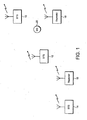
- Figure 1 illustrates an exemplary mobile communications system environment in which the present invention may be utilised.
- the present invention is not limited to such an environment, and the more general applicability of the present invention will become apparent on reading the following description.
- the mobile communications system includes a first base transceiver station (BTS) BTS1 10, a second base transceiver station BTS2 12, and a third base transceiver station BTS3 14.
- the third base transceiver station 14 is associated with a first repeater 16 and a second repeater 18, the third base transceiver station 14 being a donor base station for the repeaters 16 and 18.
- a mobile station (MS) 20 receives radio signals from one or all of the base transceiver base stations or the repeaters.
- the network infrastructure is designed such that repeaters 16 and 18 provide signals for the BTS 14 in geographical areas not reached directly by the BTS 14.
- the location of each of the BTSs 10, 12, 14 and the repeaters 16, 18 is known by the network, and more particularly is known by the means for calculating the location of the MS.
- the means for calculating the location of the MS the 'location calculation unit', is provided in the network.
- the invention is not limited to such, and it will be understood by one skilled in the art that the location calculation unit may be alternatively located, e.g. in the MS itself.
- Figure 1 is not drawn to scale. Figure 1 is merely intended to convey an example scenario where an MS receives a signal from at least one repeater.
- the mobile station 20 receives radio signals from each of the base transceiver stations 10, 12 and from the repeater 18.
- the MS measures the signal only from the donor BTS or one of the repeaters (ie. the signal from a particular BTS has only one physical signal path).
- the physical path is from the BTS 14, to the repeater 16, to the repeater 18, and to the MS 20.
- each of the base transceiver stations 10, 12, and 14 transmit control signals, which are received by the mobile station 20.
- the control signals include information that is used by the network for determining which BTS should serve the MS. Such techniques are well known in the art.
- Repeaters, where provided, also re-transmit the control signals.
- the mobile station 20 is connected to one of the base stations 10,12,14 for the purposes of a call connection. Any connection to the base station 14 may be via one of the repeaters 16,18.
- the mobile station 20 receives control signals on the air interface from all base transceiver stations and repeaters within radio range. As discussed above, in the present example this comprises the base transceiver base stations 10, 12 and the repeater 18. Based on these received signals, the MS 20 provides to the network measurement information which is used by the location calculation unit.
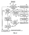
- the location calculation unit determines whether control signals have been received which are associated with any base transceiver station which is connected to one or more repeaters.
- the network stores information as to whether any BTS is a donor BTS, and therefore can determine this information based on the BTS identity in the information returned from the MS.
- step 104 If in step 104 it is determined that no base transceiver stations are associated with repeaters, then the location calculation unit (location calculation server) moves to step 106 and a location calculation is performed as is well known in the art.
- a first base transceiver station associated with a repeater is selected.
- a first base transceiver station may be selected in a number of possible ways, for example on a random selection or on the basis of the strongest received signal.
- BTS 14 the measurement and network data information associated with that BTS is stored, and the measurements kept unchanged for the purpose of the following steps.
- a location estimate is calculated using a known location algorithm.
- the location algorithm may make use of all the measurement and network data information that has been delivered to the location calculation unit from all BTSs/repeaters, but may also only be partly based on that information. This location algorithm may be the same as utilized in step 106.
- the location algorithm in step 110 thus preferably uses the information from all BTSs whether or not connected to the repeater. For those which are already studied (in accordance with the following steps) the best estimate for the signal path is used.
- the location calculation unit has calculated an estimate of the MS physical location, i.e. has determined a location estimate.
- the location calculation unit calculates additional estimates and model values as described in more detail hereinafter.
- This scaling factor is provided as most of the available models for the measurements, for use in step 2 above, have a number of empirical parameters.
- the use of the scaling factor is not essential to the present invention, but is preferably used to provide more reliable results.
- a measure of a difference between d MOD i and d EST i , diff is calculated.
- variance is only one example for providing a measure of difference. What is important is to provide a value that can be used for comparison purposes.
- a variance is used herein as an example, as variance is commonly used to describe how much a measured quantity is spread.
- Alternative possibilities for providing the measure of difference may, for example, be to use the sum of absolute values of differences.
- any quantity that does not have a sign associated with it, and is obtained as a difference between the two distances, may be used.
- the purpose of the measure of difference is to introduce a cost factor that is to be minimized.
- the location calculation unit has determined, for this example, a measure of difference based on the assumption that the MS has received a signal from the donor BTS 14 directly.
- the location calculation unit determines whether all the repeaters associated with the particular donor BTS 14 have been considered. At this stage, only the BTS itself has been considered, and not any of the repeaters. As such, in the example scenario of Figure 1 , there are still the two repeaters 16 and 18 to consider.
- the location calculation unit therefore moves on to step 126, and a repeater is selected.
- the selection of the repeater may be arbitrary, as all repeaters have to be considered.
- the measurement and network data information for that repeater is selected, i.e. the information associated with the signal from the BTS 14, and the steps 110 to 116 repeated for that repeater.
- step 112 above d EST i for the BTS 14 is now changed to the distance between the new estimate and the corresponding repeater.
- step 118 it is determined that one repeater remains to be processed, and in step 126 repeater 18 is selected. Repeater 18 is then selected, and processed.
- the location calculation unit has calculated a measure of difference for each of: the donor base transceiver station 14, the repeater 16 and the repeater 18.
- step 118 it is determined that all repeaters associated with the particular donor BTS have been considered, and the location calculation unit moves on to step 120.
- step 120 the location calculation unit determines which of the measure of difference values from the donor base transceiver station and each of the repeaters is the smallest. That is, step 120 determines which of the BTS 14 and the repeaters 16, 18 gives rise to the minimum measure for a difference between d MOD i and d EST i , diff. This is determined by a simple comparison operation.
- the invention identifies the smallest measure of difference, as the distribution of the distance from the model for measurements is most heavily peaked around the values that result for the MS location estimate BTS distances. This indicates that they are the least contradicting measurements in the final set used in the location calculation. If, for example, there is just one BTS connected to a repeater, that measurement would be contradicting with the location estimate if the wrong signal path is used in the location estimation. With the correct signal path the measurement from the BTS connected to a repeater does not contradict the location estimate. Similarly, as a location estimate depends on the selected signal path, the same applies to the other BTSs (not connected to repeater).
- the real physical path is via repeater 18.
- BTS 14 and repeater 16 (as selected signal paths) would give inconsistent results.
- the measurements and the models are considered as exact, in this example, for simplicity.
- selecting the signal path via the repeater 18 would give a correct distance (repeater 18 to MS distance)
- selecting the path via repeater 16 would give an incorrect distance (for repeater 16 to MS) and similarly also for BTS 14 to MS.
- Any measurements show that the MS is slightly closer to the BTS 10 than to BTS 12, and that BTS 10 to MS distance is roughly the same as repeater 18 to MS distance. If it is assumed that each repeater is amplifying the signal so that it is transmitted from the repeater at the same signal strength as from the donor BTS; the measurement from BTS 14 always indicates the distance between MS and repeater 18, regardless the selected signal path.
- step 122 the location calculation unit selects the network information and modifies the measurements for the one of the BTS 14 and repeaters 16,18 which returned the lowest measure of difference.
- the measurements sent to location algorithm should only correspond to the path between MS and the one selected donor/repeater.
- the modifications are carried out to delete the effect of the donor-repeater path (e.g. to delete the extra time from the measurement, or to calculate the strength of signal at the actual transmitting antenna (donor/repeater).
- the modifications may consider the repeater gain, losses in the path from a donor, extra delays introduced by a repeater, and for indoor repeater assumption that the signals from the other BTS are coming outside can be made etc.
- Various possible considerations for modifying the measurements will be apparent to one skilled in the art. These modifications are outside the scope of the present invention.
- the location calculation unit determines whether all donor base transceiver stations, i.e. every BTS connected to repeater(s), has been considered. If there are still donor BTSs to be considered, then all the above described steps 108 to 122 are repeated.
- step 106 the location calculation unit calculates a final location estimate.
- the location algorithm receives a set of known locations (BTS coordinates or repeater coordinates) and corresponding measurements and other Network information. Based on this information the location algorithm calculates a location estimate. For each BTS which can be connected to a repeater only one path is delivered to the location algorithm, and that path is selected in accordance with the present invention.
- the location calculation unit produces more accurate/reliable results, because the selection of the signal path is more accurate.
- the value d EST i is equal to the value d MODEL i for each BTS for the case of the correct signal path, where any data received from the repeater (if the correct path is not directly from the BTS) is modified accordingly. Furthermore the value d EST i would not be equal to d MODEL i for (at least) some BTSs in the case of the wrong signal path used in the calculation.
- step 110 does not give perfect location estimates with no error, nor does the model for the measurement (step 112) deliver exact ideal distances.
- selecting the signal path leading to minimum discrepancy between the two sets of distances (a measure of the discrepancy is calculated in the step 116 of Figure 2 ) is inherently most consistent and provides the selection of the actually used signal path with high probability.
- step 2 of step 112 may be modified in dependence on the specific information available in any given implementation.
- the measure for the difference in step 112 may preferably be calculated from all available history data.
- FIG. 3 for completeness there is illustrated in an example architecture of a network element for implementing the present invention as described in the preferred embodiment hereinabove.
- the present invention is preferably implemented in a network element, although it will be apparent to one skilled in the art that it may alternatively be implemented elsewhere, for example in a mobile station.
- the network element includes an input means 202, a pre-processing means 204, a location calculation means 206, and further location calculation means 208, a distance estimator 210, a model estimator 212, a scale determinator 214, a difference measure calculator 216, a comparator 218 and a control block 220.
- the location calculation unit of Figure 3 receives measurements and network data at the input means 202.
- the pre-processing means 204 in conjunction with a control block 220, performs the operation of method step 104.
- the location calculation means 208 performs the function of method step 110.
- the distance estimator block 210 and the model estimator block 212 perform the respective parts of method step 112, namely calculating the distance estimates and model estimates.
- the scale determinator 214 performs the method step 114 of determining the scale.
- the difference measure calculator 216 performs method step 116, and calculates the difference measurement.
- the comparator block 218 performs method step 120 to determine which difference measurement is the smallest, after the control block 220 in conjunction with the pre-processing means 204 has determined whether all the repeaters for the particular base transceiver station have been considered in method step 118.
- the control block 220 controls the various elements of the location calculation unit 200 to repeat various method steps, if further base transceiver stations need to be considered.
- the control block 220 also carries out any necessary modification to network and measurements corresponding to the method step 122.
- the location calculation means 206 performs the final location calculation method step 106, and outputs the location estimate.
- the invention can thus be used to detect the correct signal path if repeaters exist in the network for all measured cells.
- the invention can be applied even with minimum information available from the network cells.
- the invention does not introduce any new parameters.
- the implementation of the invention is straightforward and it can be easily added to existing products.
- the invention is not restricted for a particular location algorithm or particular type of measurements, and thus the invention may be utilised in a wide range of situations.
Landscapes
- Engineering & Computer Science (AREA)
- Signal Processing (AREA)
- General Physics & Mathematics (AREA)
- Radar, Positioning & Navigation (AREA)
- Remote Sensing (AREA)
- Computer Networks & Wireless Communication (AREA)
- Physics & Mathematics (AREA)
- Mobile Radio Communication Systems (AREA)
- Radio Relay Systems (AREA)
- Alarm Systems (AREA)
- Monitoring And Testing Of Transmission In General (AREA)
- Radar Systems Or Details Thereof (AREA)
- Amplifiers (AREA)
Claims (35)
- Verfahren zum Bestimmen des Pfads eines Signals zwischen einem Geber-Netzwerkelement (14) und einer entfernten Station (20), wobei das Geber-Netzwerkelement (14) mit mindestens einem Repeater (16, 18) verknüpft ist, umfassend die Schritte:- Empfangen von mehreren Signalen, die mit mehreren Netzwerkelementen (10, 12, 14) verknüpft sind, an der entfernten Station (20);- Berechnen einer Abschätzung der Entfernung zwischen der entfernten Station (20) und jedem Netzwerkelement (10, 12, 14), basierend auf den mehreren empfangenen Signalen, einschließlich einer Abschätzung der Entfernung zwischen der entfernten Station (20) und jedem Repeater (16, 18), der mit dem Geber-Netzwerkelement (14) verknüpft ist;- Bestimmen von derjenigen der Abschätzungen der Entfernung zwischen der entfernten Station (20) und dem Geber-Netzwerkelement (14) und der Entfernung zwischen der entfernten Station (20) und dem mindestens einen verknüpften Repeater (16, 18), die der Entfernung zwischen den anderen Netzwerkelementen (10, 12) und der entfernten Station (20) am nächsten kommt; und- Auswählen dieses Geber-Netzwerkelements/Repeaters als Quelle des Signals.
- Verfahren nach Anspruch 1, wobei der Schritt des Berechnens einer Abschätzung der Entfernung zwischen der entfernten Station (20) und jedem Netzwerkelement (10, 12, 14) umfasst:- Auswählen von jedem der Netzwerkelemente (10, 12, 14) und von mindestens einem Repeater (16, 18) nacheinander als Quelle des Signals; und- Ausführen des Berechnungsschritts für nur das Ausgewählte des Geber-Netzwerkelements (14) und des mindestens einen Repeaters (16, 18).
- Verfahren nach Anspruch 1 oder 2, wobei der Schritt des Berechnens der Abschätzung der Entfernung ein Abschätzen des Standorts der entfernten Station (20) und dadurch Abschätzen einer tatsächlichen Entfernung zwischen jedem Geber-Netzwerkelement/Repeater und der entfernten Station (20) einschließt.
- Verfahren nach Anspruch 3, wobei der Schritt des Berechnens der Abschätzung der Entfernung ein Messen von physikalischen Größen bei der entfernten Station (20) und dadurch Abschätzen einer Modell-Entfernung zwischen jedem Geber-Netzwerkelement/Repeater und der entfernten Station (20) einschließt.
- Verfahren nach Anspruch 4, wobei die gemessenen physikalischen Größen die Messung an der entfernten Station (20) von einem oder allen einschließen von- Zeitverzögerung in einem empfangenen Signal;- Dämpfung in einem empfangenen Signal; oder- Stärke des empfangenen Signals.
- Verfahren nach Anspruch 5, wobei der Schritt des Abschätzens der tatsächlichen Entfernungen weiter ein Summieren der abgeschätzten tatsächlichen Entfernungen umfasst.
- Verfahren nach Anspruch 6, wobei der Schritt des Abschätzens der Modell-Entfernungen weiter ein Summieren der Modell-Entfernungen umfasst.
- Verfahren nach Anspruch 7, weiter einschließend das Berechnen eines Skalierungsfaktors in Abhängigkeit von den summierten tatsächlichen und Modell-Entfernungen.
- Verfahren nach Anspruch 8, wobei der Skalierungsfaktor dazu bestimmt ist, die skalierten Summen so anzupassen, dass sie gleich sind.
- Verfahren nach Anspruch 9, wobei der Skalierungsfaktor durch Teilen der summierten tatsächlichen Abschätzungen durch die summierten ModellAbschätzungen bestimmt wird.
- Verfahren nach Anspruch 9 oder Anspruch 10, wobei die Abschätzungen der Modell-Entfernungen in Abhängigkeit von dem Skalierungsfaktor modifiziert werden, um einen Satz modifizierter Modell-Entfernungen zu erzeugen.
- Verfahren nach Anspruch 11, wobei die Modell-Entfernungen mit dem Skalierungsfaktor skaliert werden, um die modifizierten Modell-Entfernungen zu erzeugen.
- Verfahren nach Anspruch 12, weiter einschließend das Berechnen eines Differenzwerts für jedes Geber-Netzwerkelement (14) und mindestens einen Repeater (16, 18) durch Summieren der Differenz zwischen jeder Abschätzung und jeder modifizierten Modellabschätzung, die für jedes jeweilige Geber-Netzwerkelement (14) und mindestens einen Repeater (16, 18) erhalten werden.
- Verfahren nach Anspruch 13, wobei bestimmt wird, dass das Signal von dem Geber-Netzwerkelement (14) oder mindestens einen Repeater (16, 18) mit dem niedrigsten Differenzwert gesendet wird.
- Verfahren nach irgendeinem der Ansprüche 1 bis 14, wobei mehrere Signale von einem Geber-Netzwerkelement (14) stammen, wobei alle Schritte für jedes derartige Signal wiederholt werden, um eine Quelle von jedem Signal zu bestimmen.
- Verfahren nach irgendeinem vorhergehenden Anspruch, weiter umfassend den Schritt des Berechnens des Standorts der entfernten Station (20) in Abhängigkeit von der bestimmten Quelle des Signals.
- Verfahren nach irgendeinem vorhergehenden Anspruch, wobei die entfernte Station (20) eine Mobilstation ist und das Geber-Netzwerkelement (14) eine Geber-Basisstation ist.
- Netzwerkelement (20), angepasst, um den Pfad eines Signals zwischen einem Geber-Netzwerkelement (14) und einer entfernten Station (20) zu bestimmen, wobei das Geber-Netzwerkelement (14) mit mindestens einem Repeater (16, 18) verknüpft ist, umfassend- Mittel zum Berechnen einer Abschätzung der Entfernung zwischen der entfernten Station (20) und jedem Netzwerkelement (10, 12, 14), einschließlich einer Abschätzung der Entfernung zwischen der entfernten Station (20) und jedem Repeater (16, 18), der mit dem Geber-Netzwerkelement (14) verknüpft ist, basierend auf mehreren Signalen, die an einer Mobilstation (20) empfangen werden;- Mittel zum Bestimmen von derjenigen der Abschätzungen der Entfernung zwischen der entfernten Station (20) und dem Geber-Netzwerkelement (14) und der Entfernung zwischen der entfernten Station (20) und dem mindestens einen verknüpften Repeater (16, 18) und der entfernten Station (20), die der Entfernung zwischen den anderen Netzwerkelementen (10, 12) und der entfernten Station (20) am nächsten kommt; und- Mittel zum Auswählen dieses Geber-Netzwerkelements/Repeaters als Quelle des Signals.
- Netzwerkelement (200) nach Anspruch 18, wobei die entfernte Station (20) eine Mobilstation ist und das Netzwerkelement (10, 12, 14) eine Basisstation ist.
- Netzwerkelement (200) nach Anspruch 18 oder Anspruch 19, wobei das Mittel zum Berechnen einer Abschätzung der Entfernung zwischen der entfernten Station (20) und jedem Netzwerkelement (10, 12, 14) einschließt:- Mittel zum Auswählen von jedem der Netzwerkelemente (10, 12, 14) und von mindestens einem Repeater (16, 18) nacheinander als Quelle des Signals; und- Mittel zum Ausführen des Berechnungsschritts für nur das Ausgewählte des Geber-Netzwerkelements (14) und des mindestens einen Repeaters (16, 18).
- Netzwerkelement (200) nach irgendeinem der Anspruch 18 bis 20, wobei das Mittel zum Berechnen der Abschätzung der Entfernung Mittel zum Abschätzen des Standorts der entfernten Station (20) und dadurch Abschätzen einer tatsächlichen Entfernung zwischen jedem Geber-Netzwerkelement/Repeater und der entfernten Station (20) einschließt.
- Netzwerkelement (200) nach Anspruch 21, wobei das Mittel zum Berechnen der Abschätzung der Entfernung Mittel zum Messen von physikalischen Größen an der entfernten Station (20) und dadurch Abschätzen einer Modell-Entfernung zwischen jedem Netzwerkelement/Repeater und der entfernten Station (20) einschließt.
- Netzwerkelement (200) nach Anspruch 22, wobei die gemessene physikalische Größe die Messung an der entfernten Station (20) von einem oder allen einschließt von- Zeitverzögerung in einem empfangenen Signal;- Dämpfung in einem empfangenen Signal; oder- Stärke des empfangenen Signals.
- Netzwerkelement (200) nach Anspruch 23, wobei das Mittel zum Abschätzen der tatsächlichen Entfernungen weiter Mittel zum Summieren der abgeschätzten tatsächlichen Entfernungen einschließt.
- Netzwerkelement (200) nach Anspruch 24, wobei das Mittel zum Abschätzen der Modell-Entfernungen weiter Mittel zum Summieren der Modell-Entfernungen einschließt.
- Netzwerkelement (200) nach Anspruch 25, weiter einschließend Mittel zum Berechnen eines Skalierungsfaktors in Abhängigkeit von den summierten tatsächlichen und Modell-Entfernungen.
- Netzwerkelement (200) nach Anspruch 26, wobei das Mittel zum Berechnen des Skalierungsfaktors angepasst ist, die skalierten Summen so umzuwandeln, dass sie gleich sind.
- Netzwerkelement (200) nach Anspruch 27, wobei der Skalierungsfaktor durch Teilen der summierten tatsächlichen Abschätzungen durch die summierten Modellabschätzungen bestimmt wird.
- Netzwerkelement (200) nach Anspruch 27 oder Anspruch 28, wobei die Abschätzungen der Modell-Entfernungen in Abhängigkeit von dem Skalierungsfaktor modifiziert werden, um einen Satz von modifizierten Modell-Entfernungen zu erzeugen.
- Netzwerkelement (200) nach Anspruch 29, wobei die Modell-Entfernungen mit dem Skalierungsfaktor skaliert werden, um die modifizierten Modell-Entfernungen zu erzeugen.
- Netzwerkelement (200) nach Anspruch 30, weiter einschließend Mittel zum Berechnen eines Differenzwerts für jedes Geber-Netzwerkelement (14) und mindestens einen Repeater (16, 18), einschließend einen Summierer zum Summieren der Differenz zwischen jeder Abschätzung und jeder modifizierten Modellabschätzung, die für jedes jeweilige Geber-Netzwerkelement (14) und mindestens einen Repeater (16, 18) erhalten werden.
- Netzwerkelement (200) nach Anspruch 31, wobei bestimmt wird, dass das Signal von dem Geber-Netzwerkelement (14) oder mindestens einen Repeater (16, 18) mit dem niedrigsten Differenzwert gesendet wird.
- Netzwerkelement (200) nach irgendeinem der Ansprüche 18 bis 32, wobei mehrere Signale von einem Geber-Netzwerkelement (14) empfangen werden, wobei alle Schritte für jedes derartige Signal wiederholt werden, um eine Quelle von jedem Signal zu bestimmen.
- Netzwerkelement (200) nach irgendeinem der Ansprüche 18 bis 33, weiter umfassend Mittel zum Berechnen des Standorts der entfernten Station (20) in Abhängigkeit von der bestimmten Quelle des Signals.
- Ein Computerprogramm, umfassend Codemittel, die angepasst sind, die Schritte von irgendeinem der Ansprüche 1 bis 17 durchzuführen, wenn sie in einer Netzwerkvorrichtung ausgeführt werden.
Applications Claiming Priority (1)
| Application Number | Priority Date | Filing Date | Title |
|---|---|---|---|
| PCT/IB2002/003198 WO2004002182A1 (en) | 2002-06-21 | 2002-06-21 | Signal path detection for wireless networks including repeaters |
Publications (2)
| Publication Number | Publication Date |
|---|---|
| EP1516505A1 EP1516505A1 (de) | 2005-03-23 |
| EP1516505B1 true EP1516505B1 (de) | 2008-10-29 |
Family
ID=29798177
Family Applications (1)
| Application Number | Title | Priority Date | Filing Date |
|---|---|---|---|
| EP02765154A Expired - Lifetime EP1516505B1 (de) | 2002-06-21 | 2002-06-21 | Signalwegdetektion für drahtlose netzwerke mit zwischenverstärkern |
Country Status (8)
| Country | Link |
|---|---|
| US (1) | US7412207B2 (de) |
| EP (1) | EP1516505B1 (de) |
| KR (1) | KR100652259B1 (de) |
| CN (1) | CN100381007C (de) |
| AT (1) | ATE413076T1 (de) |
| AU (1) | AU2002329524A1 (de) |
| DE (1) | DE60229671D1 (de) |
| WO (1) | WO2004002182A1 (de) |
Families Citing this family (19)
| Publication number | Priority date | Publication date | Assignee | Title |
|---|---|---|---|---|
| US7039418B2 (en) * | 2000-11-16 | 2006-05-02 | Qualcomm Incorporated | Position determination in a wireless communication system with detection and compensation for repeaters |
| US8003122B2 (en) | 2004-03-31 | 2011-08-23 | Cordis Corporation | Device for local and/or regional delivery employing liquid formulations of therapeutic agents |
| JP2007537613A (ja) * | 2004-09-17 | 2007-12-20 | ラディアント テクノロジーズ,インク. | 移動通信端末機の位置決定方法およびシステム |
| KR101002903B1 (ko) * | 2005-11-07 | 2010-12-21 | 삼성전자주식회사 | 멀티 홉 무선 이동 통신 시스템에서 서빙 노드 결정 방법 |
| CN101064913B (zh) * | 2006-04-29 | 2012-05-16 | 上海贝尔阿尔卡特股份有限公司 | 无线网络中用于扩展基站覆盖范围的中继站、基站及其方法 |
| US8221496B2 (en) | 2007-02-01 | 2012-07-17 | Cordis Corporation | Antithrombotic and anti-restenotic drug eluting stent |
| KR100833300B1 (ko) * | 2007-02-05 | 2008-05-29 | (주)래디안트 | 중계기 신호 여부 판단 방법 및 이를 이용한 판단 장치 |
| EP2158783B1 (de) * | 2007-05-22 | 2018-12-12 | Telstra Corporation Limited | Repeater-system für erweiterte zellenabdeckung |
| KR101400794B1 (ko) * | 2007-11-06 | 2014-05-30 | 주식회사 케이엠더블유 | 이동체에서의 이동통신 중계 방법 및 그 중계기 |
| US9603980B2 (en) | 2008-02-26 | 2017-03-28 | CARDINAL HEALTH SWITZERLAND 515 GmbH | Layer-by-layer stereocomplexed polymers as drug depot carriers or coatings in medical devices |
| US8409601B2 (en) | 2008-03-31 | 2013-04-02 | Cordis Corporation | Rapamycin coated expandable devices |
| US8420110B2 (en) | 2008-03-31 | 2013-04-16 | Cordis Corporation | Drug coated expandable devices |
| US8273404B2 (en) | 2008-05-19 | 2012-09-25 | Cordis Corporation | Extraction of solvents from drug containing polymer reservoirs |
| US7819914B2 (en) | 2008-12-16 | 2010-10-26 | Cordis Corporation | Adhesion promoting primer for coated surfaces |
| US20100161039A1 (en) | 2008-12-23 | 2010-06-24 | Vipul Dave | Adhesion promoting temporary mask for coated surfaces |
| EP2213264A1 (de) | 2009-01-30 | 2010-08-04 | Cordis Corporation | Eluierender Stent mit Reservoir |
| US20100280600A1 (en) | 2009-04-30 | 2010-11-04 | Vipul Bhupendra Dave | Dual drug stent |
| US20110137407A1 (en) | 2009-07-09 | 2011-06-09 | Thai Minh Nguyen | Bare metal stent with drug eluting reservoirs |
| US10051608B2 (en) * | 2015-11-10 | 2018-08-14 | At&T Mobility Ii Llc | Facilitation of channel selection within a wireless network |
Family Cites Families (6)
| Publication number | Priority date | Publication date | Assignee | Title |
|---|---|---|---|---|
| US5260943A (en) * | 1992-06-16 | 1993-11-09 | Motorola, Inc. | TDM hand-off technique using time differences |
| JPH11205845A (ja) * | 1998-01-14 | 1999-07-30 | Locus:Kk | 位置特定システム |
| EP1127473A1 (de) * | 1999-09-07 | 2001-08-29 | Koninklijke Philips Electronics N.V. | Verfahren zur berechnung des standorts einer mobilfunkstation basierend auf der kürzesten signallaufzeit |
| US6501955B1 (en) | 2000-06-19 | 2002-12-31 | Intel Corporation | RF signal repeater, mobile unit position determination system using the RF signal repeater, and method of communication therefor |
| FI109839B (fi) * | 2000-08-22 | 2002-10-15 | Nokia Corp | Menetelmä matkaviestimen paikantamiseksi |
| US7039418B2 (en) * | 2000-11-16 | 2006-05-02 | Qualcomm Incorporated | Position determination in a wireless communication system with detection and compensation for repeaters |
-
2002
- 2002-06-21 KR KR1020047019941A patent/KR100652259B1/ko not_active Expired - Fee Related
- 2002-06-21 US US10/518,505 patent/US7412207B2/en not_active Expired - Lifetime
- 2002-06-21 CN CNB028291921A patent/CN100381007C/zh not_active Expired - Lifetime
- 2002-06-21 EP EP02765154A patent/EP1516505B1/de not_active Expired - Lifetime
- 2002-06-21 AU AU2002329524A patent/AU2002329524A1/en not_active Abandoned
- 2002-06-21 DE DE60229671T patent/DE60229671D1/de not_active Expired - Lifetime
- 2002-06-21 WO PCT/IB2002/003198 patent/WO2004002182A1/en not_active Ceased
- 2002-06-21 AT AT02765154T patent/ATE413076T1/de not_active IP Right Cessation
Also Published As
| Publication number | Publication date |
|---|---|
| KR20050004297A (ko) | 2005-01-12 |
| WO2004002182A1 (en) | 2003-12-31 |
| DE60229671D1 (de) | 2008-12-11 |
| KR100652259B1 (ko) | 2006-12-01 |
| CN1628480A (zh) | 2005-06-15 |
| EP1516505A1 (de) | 2005-03-23 |
| CN100381007C (zh) | 2008-04-09 |
| ATE413076T1 (de) | 2008-11-15 |
| US7412207B2 (en) | 2008-08-12 |
| US20050221754A1 (en) | 2005-10-06 |
| AU2002329524A1 (en) | 2004-01-06 |
Similar Documents
| Publication | Publication Date | Title |
|---|---|---|
| US7412207B2 (en) | Signal path detection for wireless networks including repeaters | |
| EP1514130B1 (de) | Probabilistisches modell für eine positionierungstechnik | |
| EP2045613B1 (de) | Berechnung des geographischen Standorts eines mobilen Empfängers unter Verwendung von Netzwerkmessberichten | |
| US6263208B1 (en) | Geolocation estimation method for CDMA terminals based on pilot strength measurements | |
| US7460505B2 (en) | Location estimation of wireless terminals through pattern matching of signal-strength differentials | |
| EP1286174B1 (de) | Funkhandgerät und Ortungssystem | |
| EP1510099B1 (de) | Verfahren zur Ortung eines Mobilendgeräts sowie zugehöriges System und Komponenten | |
| KR100939027B1 (ko) | 이동단말 위치 결정 | |
| CN1114832C (zh) | 在加权最小二乘法位置解决方案中协方差矩阵估计的方法和设备 | |
| EP1506686B1 (de) | Verbesserte positionsbestimmung in drahtlosen kommunikationssystemen | |
| US9660740B2 (en) | Signal strength distribution establishing method and wireless positioning system | |
| US20050014511A1 (en) | Location estimation of wireless terminals through pattern matching of deduced signal strengths | |
| US20020052208A1 (en) | Mobile radio terminal and related method and system | |
| KR20040016453A (ko) | 이동 단말기의 위치 추적 장치 및 방법 | |
| EP2214031A1 (de) | Empfänger-positionierung und positionierungsverfahren für benutzergeräte | |
| CN118302688A (zh) | 实现无线终端的位置估计的方法、第一无线节点和定位节点 | |
| EP2480908A1 (de) | Schätzung eines standortes eines benutzergeräts in einem drahtlosen netz | |
| US9414350B1 (en) | Determining a propagation-time adjustment for a wireless coverage area, based on information provided by wireless terminals | |
| JP2008128726A (ja) | 粒子フィルタを用いた測位システム、装置および方法 | |
| KR100857749B1 (ko) | 위치 결정 시스템에서의 중계기 식별 | |
| US7579990B2 (en) | Method and system for estimating the location of a wireless terminal from a received signal strength | |
| KR100876204B1 (ko) | 이동단말 위치 결정 | |
| EP1527650B1 (de) | Anwendungen von signalqualität-beobachtungen | |
| EP1197111B1 (de) | Standorterfassung für eine mobilstation eines telekommunikationssystems | |
| CN113970767A (zh) | 卫星定位方法、定位设备及用户终端 |
Legal Events
| Date | Code | Title | Description |
|---|---|---|---|
| PUAI | Public reference made under article 153(3) epc to a published international application that has entered the european phase |
Free format text: ORIGINAL CODE: 0009012 |
|
| 17P | Request for examination filed |
Effective date: 20041126 |
|
| AK | Designated contracting states |
Kind code of ref document: A1 Designated state(s): AT BE CH CY DE DK ES FI FR GB GR IE IT LI LU MC NL PT SE TR |
|
| AX | Request for extension of the european patent |
Extension state: AL LT LV MK RO SI |
|
| DAX | Request for extension of the european patent (deleted) | ||
| 17Q | First examination report despatched |
Effective date: 20061214 |
|
| GRAP | Despatch of communication of intention to grant a patent |
Free format text: ORIGINAL CODE: EPIDOSNIGR1 |
|
| RIC1 | Information provided on ipc code assigned before grant |
Ipc: G01S 5/02 20060101ALI20080429BHEP Ipc: H04Q 7/38 20060101AFI20080429BHEP |
|
| GRAS | Grant fee paid |
Free format text: ORIGINAL CODE: EPIDOSNIGR3 |
|
| GRAA | (expected) grant |
Free format text: ORIGINAL CODE: 0009210 |
|
| AK | Designated contracting states |
Kind code of ref document: B1 Designated state(s): AT BE CH CY DE DK ES FI FR GB GR IE IT LI LU MC NL PT SE TR |
|
| REG | Reference to a national code |
Ref country code: GB Ref legal event code: FG4D |
|
| REG | Reference to a national code |
Ref country code: CH Ref legal event code: EP |
|
| REG | Reference to a national code |
Ref country code: IE Ref legal event code: FG4D |
|
| REF | Corresponds to: |
Ref document number: 60229671 Country of ref document: DE Date of ref document: 20081211 Kind code of ref document: P |
|
| NLV1 | Nl: lapsed or annulled due to failure to fulfill the requirements of art. 29p and 29m of the patents act | ||
| PG25 | Lapsed in a contracting state [announced via postgrant information from national office to epo] |
Ref country code: ES Free format text: LAPSE BECAUSE OF FAILURE TO SUBMIT A TRANSLATION OF THE DESCRIPTION OR TO PAY THE FEE WITHIN THE PRESCRIBED TIME-LIMIT Effective date: 20090209 Ref country code: AT Free format text: LAPSE BECAUSE OF FAILURE TO SUBMIT A TRANSLATION OF THE DESCRIPTION OR TO PAY THE FEE WITHIN THE PRESCRIBED TIME-LIMIT Effective date: 20081029 |
|
| PG25 | Lapsed in a contracting state [announced via postgrant information from national office to epo] |
Ref country code: NL Free format text: LAPSE BECAUSE OF FAILURE TO SUBMIT A TRANSLATION OF THE DESCRIPTION OR TO PAY THE FEE WITHIN THE PRESCRIBED TIME-LIMIT Effective date: 20081029 Ref country code: PT Free format text: LAPSE BECAUSE OF FAILURE TO SUBMIT A TRANSLATION OF THE DESCRIPTION OR TO PAY THE FEE WITHIN THE PRESCRIBED TIME-LIMIT Effective date: 20090330 Ref country code: FI Free format text: LAPSE BECAUSE OF FAILURE TO SUBMIT A TRANSLATION OF THE DESCRIPTION OR TO PAY THE FEE WITHIN THE PRESCRIBED TIME-LIMIT Effective date: 20081029 |
|
| PG25 | Lapsed in a contracting state [announced via postgrant information from national office to epo] |
Ref country code: DK Free format text: LAPSE BECAUSE OF FAILURE TO SUBMIT A TRANSLATION OF THE DESCRIPTION OR TO PAY THE FEE WITHIN THE PRESCRIBED TIME-LIMIT Effective date: 20081029 Ref country code: BE Free format text: LAPSE BECAUSE OF FAILURE TO SUBMIT A TRANSLATION OF THE DESCRIPTION OR TO PAY THE FEE WITHIN THE PRESCRIBED TIME-LIMIT Effective date: 20081029 |
|
| PG25 | Lapsed in a contracting state [announced via postgrant information from national office to epo] |
Ref country code: SE Free format text: LAPSE BECAUSE OF FAILURE TO SUBMIT A TRANSLATION OF THE DESCRIPTION OR TO PAY THE FEE WITHIN THE PRESCRIBED TIME-LIMIT Effective date: 20090129 Ref country code: IT Free format text: LAPSE BECAUSE OF FAILURE TO SUBMIT A TRANSLATION OF THE DESCRIPTION OR TO PAY THE FEE WITHIN THE PRESCRIBED TIME-LIMIT Effective date: 20081029 |
|
| PLBE | No opposition filed within time limit |
Free format text: ORIGINAL CODE: 0009261 |
|
| STAA | Information on the status of an ep patent application or granted ep patent |
Free format text: STATUS: NO OPPOSITION FILED WITHIN TIME LIMIT |
|
| 26N | No opposition filed |
Effective date: 20090730 |
|
| PG25 | Lapsed in a contracting state [announced via postgrant information from national office to epo] |
Ref country code: MC Free format text: LAPSE BECAUSE OF NON-PAYMENT OF DUE FEES Effective date: 20090630 |
|
| REG | Reference to a national code |
Ref country code: CH Ref legal event code: PL |
|
| PG25 | Lapsed in a contracting state [announced via postgrant information from national office to epo] |
Ref country code: IE Free format text: LAPSE BECAUSE OF NON-PAYMENT OF DUE FEES Effective date: 20090621 Ref country code: CH Free format text: LAPSE BECAUSE OF NON-PAYMENT OF DUE FEES Effective date: 20090630 Ref country code: LI Free format text: LAPSE BECAUSE OF NON-PAYMENT OF DUE FEES Effective date: 20090630 |
|
| PG25 | Lapsed in a contracting state [announced via postgrant information from national office to epo] |
Ref country code: GR Free format text: LAPSE BECAUSE OF FAILURE TO SUBMIT A TRANSLATION OF THE DESCRIPTION OR TO PAY THE FEE WITHIN THE PRESCRIBED TIME-LIMIT Effective date: 20090130 |
|
| PG25 | Lapsed in a contracting state [announced via postgrant information from national office to epo] |
Ref country code: LU Free format text: LAPSE BECAUSE OF NON-PAYMENT OF DUE FEES Effective date: 20090621 |
|
| PGFP | Annual fee paid to national office [announced via postgrant information from national office to epo] |
Ref country code: FR Payment date: 20110621 Year of fee payment: 10 |
|
| PG25 | Lapsed in a contracting state [announced via postgrant information from national office to epo] |
Ref country code: TR Free format text: LAPSE BECAUSE OF FAILURE TO SUBMIT A TRANSLATION OF THE DESCRIPTION OR TO PAY THE FEE WITHIN THE PRESCRIBED TIME-LIMIT Effective date: 20081029 |
|
| PGFP | Annual fee paid to national office [announced via postgrant information from national office to epo] |
Ref country code: GB Payment date: 20110615 Year of fee payment: 10 |
|
| PG25 | Lapsed in a contracting state [announced via postgrant information from national office to epo] |
Ref country code: CY Free format text: LAPSE BECAUSE OF FAILURE TO SUBMIT A TRANSLATION OF THE DESCRIPTION OR TO PAY THE FEE WITHIN THE PRESCRIBED TIME-LIMIT Effective date: 20081029 |
|
| GBPC | Gb: european patent ceased through non-payment of renewal fee |
Effective date: 20120621 |
|
| REG | Reference to a national code |
Ref country code: FR Ref legal event code: ST Effective date: 20130228 |
|
| PG25 | Lapsed in a contracting state [announced via postgrant information from national office to epo] |
Ref country code: GB Free format text: LAPSE BECAUSE OF NON-PAYMENT OF DUE FEES Effective date: 20120621 Ref country code: FR Free format text: LAPSE BECAUSE OF NON-PAYMENT OF DUE FEES Effective date: 20120702 |
|
| REG | Reference to a national code |
Ref country code: DE Ref legal event code: R081 Ref document number: 60229671 Country of ref document: DE Owner name: NOKIA TECHNOLOGIES OY, FI Free format text: FORMER OWNER: NOKIA CORP., 02610 ESPOO, FI Ref country code: DE Ref legal event code: R081 Ref document number: 60229671 Country of ref document: DE Owner name: HMD GLOBAL OY, FI Free format text: FORMER OWNER: NOKIA CORP., 02610 ESPOO, FI |
|
| REG | Reference to a national code |
Ref country code: DE Ref legal event code: R081 Ref document number: 60229671 Country of ref document: DE Owner name: HMD GLOBAL OY, FI Free format text: FORMER OWNER: NOKIA TECHNOLOGIES OY, ESPOO, FI |
|
| PGFP | Annual fee paid to national office [announced via postgrant information from national office to epo] |
Ref country code: DE Payment date: 20210618 Year of fee payment: 20 |
|
| REG | Reference to a national code |
Ref country code: DE Ref legal event code: R071 Ref document number: 60229671 Country of ref document: DE |