EP1516221B1 - Einrichtung und verfahren zur laserstrahlablenkung für optische messsysteme - Google Patents
Einrichtung und verfahren zur laserstrahlablenkung für optische messsysteme Download PDFInfo
- Publication number
- EP1516221B1 EP1516221B1 EP03737934A EP03737934A EP1516221B1 EP 1516221 B1 EP1516221 B1 EP 1516221B1 EP 03737934 A EP03737934 A EP 03737934A EP 03737934 A EP03737934 A EP 03737934A EP 1516221 B1 EP1516221 B1 EP 1516221B1
- Authority
- EP
- European Patent Office
- Prior art keywords
- laser beam
- optical element
- deflection
- segments
- deflected
- Prior art date
- Legal status (The legal status is an assumption and is not a legal conclusion. Google has not performed a legal analysis and makes no representation as to the accuracy of the status listed.)
- Expired - Lifetime
Links
- 230000003287 optical effect Effects 0.000 title claims abstract description 99
- 238000000034 method Methods 0.000 title claims abstract description 12
- 238000011144 upstream manufacturing Methods 0.000 claims description 4
- 230000008859 change Effects 0.000 claims description 3
- 230000007704 transition Effects 0.000 claims description 3
- 238000013461 design Methods 0.000 abstract description 2
- 238000005259 measurement Methods 0.000 description 7
- 230000008901 benefit Effects 0.000 description 3
- 239000013585 weight reducing agent Substances 0.000 description 3
- 238000012937 correction Methods 0.000 description 2
- 230000000694 effects Effects 0.000 description 2
- 238000005562 fading Methods 0.000 description 2
- 238000004519 manufacturing process Methods 0.000 description 2
- 239000000463 material Substances 0.000 description 2
- 230000007246 mechanism Effects 0.000 description 2
- 238000005070 sampling Methods 0.000 description 2
- 238000002679 ablation Methods 0.000 description 1
- 230000001133 acceleration Effects 0.000 description 1
- 230000001419 dependent effect Effects 0.000 description 1
- 238000005516 engineering process Methods 0.000 description 1
- 239000000446 fuel Substances 0.000 description 1
- 238000012545 processing Methods 0.000 description 1
- 230000005855 radiation Effects 0.000 description 1
- 230000000630 rising effect Effects 0.000 description 1
- 230000035939 shock Effects 0.000 description 1
- 230000002269 spontaneous effect Effects 0.000 description 1
Images


Classifications
-
- B—PERFORMING OPERATIONS; TRANSPORTING
- B60—VEHICLES IN GENERAL
- B60T—VEHICLE BRAKE CONTROL SYSTEMS OR PARTS THEREOF; BRAKE CONTROL SYSTEMS OR PARTS THEREOF, IN GENERAL; ARRANGEMENT OF BRAKING ELEMENTS ON VEHICLES IN GENERAL; PORTABLE DEVICES FOR PREVENTING UNWANTED MOVEMENT OF VEHICLES; VEHICLE MODIFICATIONS TO FACILITATE COOLING OF BRAKES
- B60T8/00—Arrangements for adjusting wheel-braking force to meet varying vehicular or ground-surface conditions, e.g. limiting or varying distribution of braking force
- B60T8/17—Using electrical or electronic regulation means to control braking
- B60T8/1755—Brake regulation specially adapted to control the stability of the vehicle, e.g. taking into account yaw rate or transverse acceleration in a curve
- B60T8/17554—Brake regulation specially adapted to control the stability of the vehicle, e.g. taking into account yaw rate or transverse acceleration in a curve specially adapted for enhancing stability around the vehicles longitudinal axle, i.e. roll-over prevention
-
- G—PHYSICS
- G02—OPTICS
- G02B—OPTICAL ELEMENTS, SYSTEMS OR APPARATUS
- G02B26/00—Optical devices or arrangements for the control of light using movable or deformable optical elements
- G02B26/08—Optical devices or arrangements for the control of light using movable or deformable optical elements for controlling the direction of light
- G02B26/0875—Optical devices or arrangements for the control of light using movable or deformable optical elements for controlling the direction of light by means of one or more refracting elements
- G02B26/0883—Optical devices or arrangements for the control of light using movable or deformable optical elements for controlling the direction of light by means of one or more refracting elements the refracting element being a prism
- G02B26/0891—Optical devices or arrangements for the control of light using movable or deformable optical elements for controlling the direction of light by means of one or more refracting elements the refracting element being a prism forming an optical wedge
-
- G—PHYSICS
- G02—OPTICS
- G02B—OPTICAL ELEMENTS, SYSTEMS OR APPARATUS
- G02B26/00—Optical devices or arrangements for the control of light using movable or deformable optical elements
- G02B26/08—Optical devices or arrangements for the control of light using movable or deformable optical elements for controlling the direction of light
- G02B26/10—Scanning systems
- G02B26/108—Scanning systems having one or more prisms as scanning elements
Definitions
- the invention relates to a device for laser beam deflection for optical measuring systems according to the preamble of patent claim 1, and to a method for laser beam deflection according to the preamble of patent claim 12.
- Measuring systems that work with laser beams are used in various fields of technology.
- a particular example of such optical measuring systems are air data systems which record and evaluate the properties of the air at a certain distance in precisely defined measuring directions. For example, it can be used to measure the speed of air movement in all three spatial axes, air temperature and air pressure.
- the air data systems may e.g. be provided in an airplane or helicopter, a land vehicle, a satellite or even stationary on the ground. Particular application find such air data systems in aviation, e.g. be able to detect turbulences and other important air parameters on an airplane in good time and initiate appropriate controls.
- Scanners are used, which guide the laser beam along a circular path.
- the journal SPIE, Vol. 2956, February 1997, p. 76 describes a Doppler lidar for measurement in which the velocity components of the air are measured with a pulsed light beam and a scanning mechanism.
- the scanning mechanism guides the beam over the various measuring points.
- a scanner for an air data measurement system in which a rotating mirror deflects a laser beam. Fixed mirrors guide the deflected beam out through a window of the measuring system to record the measured data.
- the publication WO 97/06462 shows an optical system in which a rotating optical element laterally displaces a laser beam and places it on a circular path.
- the document GB 2 250 884 A shows a scanner in which a laser beam with continuously varying wedge-shaped segments is deflected in different directions.
- the document GB 1 238 783 A describes a device for light beam ablation, in which an incident light beam is deflected by a rotating disk in different directions.
- document WO 99/54082 shows a method for deflecting a laser beam for material processing, in which a wedge-shaped plate rotates in order to guide a laser beam incident in the center in a circular path.
- the pulse repetition frequencies are limited at the top.
- the known systems are only suitable for continuous wave lasers or for lasers with low pulse repetition rates, since the possible pulse frequency depends on the scanning speed.
- a synchronization or triggering of each laser pulse is necessary.
- the optical losses should be kept as low as possible, and at the same time should be high power densities.
- the object of the invention is to provide a device and a method for laser beam deflection for optical measuring systems, which are suitable for operation with extremely powerful lasers, such as pulse lasers with high power and energy densities and high pulse repetition rates, and also have low optical losses.
- the device according to the invention for the laser beam device comprises an optical element for deflecting an incident laser beam and a drive unit for generating a rotational movement between the optical element and the incident laser beam in order to deflect the laser beam in different successive directions, wherein the optical element at least two segments for deflecting the incident Laser beam to each case comprises a fixed deflection angle and the laser beam in the rotational movement hits the at least two segments in succession.
- the device according to the invention comprises a rotatable deflection unit, which is connected upstream of the optical element in the beam direction and coupled to the drive element in order to displace the laser beam laterally before impinging on the optical element or to bring it into a circular path with a parallel beam axis. That is, the rotational movement between the optical element and the incident laser beam is generated by the rotational movement of the deflecting unit.
- the optical element is fixedly fixed.
- a high pulse rate can be achieved during the measurement, ie pulse lasers with arbitrarily high pulse repetition rates can be used.
- extremely powerful lasers such as pulsed lasers with high power and energy densities, can be used in optical measuring systems.
- a very high efficiency is achieved because the optical losses are extremely low with the device according to the invention. It also results in a very high directional accuracy and directional stability of the deflected laser beam and a high temperature independence.
- the device according to the invention can be constructed very stable against vibrations, shocks and accelerations and is also very compact with a small volume, which is particularly advantageous for applications in the aerospace industry.
- the device according to the invention can be realized almost wear-free or with a long service life of the bearing and it consists of only a few components, which is why it is particularly cost-effective.
- the optical element is arranged such that the incident laser beam during the rotational movement on the surface of the optical element performs a circular path.
- the optical element is preferably designed as a disk or ring and the individual segments of the optical element are preferably wedge-shaped, wherein the wedge angle of each segment defines its deflection angle.
- the segments of the optical element have surfaces which are inclined with respect to the beam axis of the incident laser beam, the angles of inclination of the surface of each segment, together with the refractive index of the optical material, defining its deflection angle.
- the deflected laser beam maintains a constant direction in space.
- the segments are designed such that the incident laser beam is deflected towards the axis of rotation or axis of symmetry.
- the window from which the laser beam exits in a corresponding optical measuring system can be kept particularly small.
- the segments deflect the incident laser beam away from the axis of rotation.
- the segments are designed such that the respective incident laser beam is deflected by each segment in another defined direction. But it can also be configured equal to several segments to during the rotational movement to deflect the laser beam several times in one and the same defined direction.
- a transition region is present between two adjoining segments, which allows a change of direction of the laser beam without interrupting the beam.
- a cross-fading from one measuring point or one measuring direction to another measuring point or another measuring direction can take place during the measurement.
- the optical element is embodied on one side, for example on the rear side, spherically or aspherically or has a spherical or aspherical surface element with a positive focal length.
- the optical element is flattened or formed as a flat surface in a partial area which is not used for beam deflection, or it has a recess in the partial area.
- the optical element is flattened or formed as a flat surface in a partial area which is not used for beam deflection, or it has a recess in the partial area.
- the optical element is preferably transparent, wherein the respective deflection angle is generated by refraction in segments. But it is also possible to design the optical element reflective, wherein the respective deflection angle is generated by reflection at the segments or segment surfaces.
- the dwell time of the deflected laser beam in a defined spatial direction can be determined as a function of the angular range of the respective segment and the rotational frequency. This results in a particularly high degree of flexibility with regard to the manner of the measurement.
- the segments preferably have a spherical or aspherical surface on one side. As a result, a correction of a parallel beam offset can be achieved.
- the segments are designed such that the beam deflection takes place toward the axis of rotation.
- the exit window for the laser beam can be kept particularly small.
- the optical element according to the invention is provided or usable in a device according to the invention for laser beam deflection. Advantages and features of the optical element according to the invention also apply to the laser beam deflection device according to the invention and vice versa.
- a method for laser beam deflection in which an incident laser beam is deflected by an optical element successively in at least two different directions, wherein an upstream deflection unit rotates, and wherein the laterally offset parallel to the axis of rotation incident laser beam during a rotation each time for a period t at least two segments of the optical element and each segment deflects the laser beam during the time t in exactly one defined direction, wherein the direction of the deflected laser beam during the time t is constant.
- the method according to the invention makes it possible, in particular, to use extremely powerful lasers or pulse lasers with arbitrarily high pulse repetition rates in optical measuring systems, and the sampling frequency of the individual measuring positions can be, for example, several hundred hertz.
- the advantages and features which are mentioned in relation to the device according to the invention and the optical element according to the invention also apply to the method according to the invention.
- the method is carried out with a device according to the invention.
- the device 10 comprises an optical element 11 with a plurality of segments 12a, 12b, which are wedge-shaped.
- the optical element 11 is configured in the form of a round disk, wherein the individual segments 12a, 12b of the disk have surfaces inclined in the radial direction.
- a deflection unit 13 in the form of a rotatable optical system is connected upstream of the fixed optical element 11 and serves to displace a laser beam 14a laterally and to bring the shifted laser beam 14b in a circular motion, wherein the beam axis is directed parallel to the original beam axis.
- the laterally offset laser beam 14b after passing through the rotating deflection unit 13 describes the lateral surface of a cylinder or a circular movement in cylindrical form.
- Fig. 2 shows the device 10 according to the invention in side section.
- the wedge shape of the individual segments 12a, 12b causes the incident laser beam 14b, each strikes the optical element 11 within a segment, at the surfaces of the wedge-shaped segments 12a, 12b is successively broken in the various desired directions.
- Each direction of the laser beam caused by a single segment 12a, 12b is exactly maintained over a segment area as the incident laser beam 14b travels.
- the individual wedges or segments 12a, 12b are prisms in this example.
- the deflection unit 13 which is mounted in rotation and is rotated by a drive unit, not shown in the figures, contains for beam deflection mirror, for example, metallic or dielectric type, as deflection, where the laser beam 14a is laterally displaced by reflection.
- beam deflection mirror for example, metallic or dielectric type
- prisms using total reflection at the deflection surfaces.
- the rotating optics or deflecting unit 13 can also be designed as a transparent monolith.
- deflecting unit 13 of the cylindrically circular laser beam 14b strikes the fixed, optically transparent optical element 11, the special shape of which breaks the laser beam in the desired direction.
- Figures 3a-3d show the optical element 11 in various embodiments in a front view.
- the optical element 11 designed as a round disk contains at its beam entrance side or front side or rear side a surface which is subdivided into four subsegments 12 a, 12 b, 12 c, 12 d.
- the laser beam 14b striking the front side of the optical element 11 substantially perpendicularly describes a circular path 15 in the edge region of the optical element 11, the incident laser beam 14b successively striking the individual segments 12a, 12b, 12c, 12d and through these in different directions in FIG Room is distracted.
- each segment 12a, 12b, 12c, 12d has a fixed deflection angle in space, so that the deflected laser beam 14c during a time t in its spatial direction remains constant, ie as long as the incident laser beam 14b is deflected by the corresponding segment.
- the optical element 11 is divided equally into two subsegments 12a, 12b, while in FIG. 3c it is divided equally into three subsegments 12a, 12b, 12c.
- the optical element 11 is shown with a subdivision into segments 12a, 12b, 12c, each occupying a different angular range of the optical element 11.
- a different dwell time of the deflected laser beam in the individual measuring positions is achieved at constant circular speed or rotational speed.
- the segment angle ⁇ of a segment 12a, 12b, 12c, 12d determines, together with the rotational frequency F in Hertz, the dwell time or measuring time T m in seconds per direction.
- T m ⁇ ( 360 ° ⁇ F )
- the number of disk or ring segments determines the number of measurement positions of the optical measuring device in which the laser deflection device is used. For example, at least two segments must therefore be formed at two positions, at least three at three positions, and so on.
- each segment 12a, 12b, 12c, 12d depends only on the wedge angle and the inclination of the wedge-shaped segment. Therefore, the accuracy of the deflection angle is determined only by manufacturing tolerances and behaves stable in time. In the realization, an optionally by bearing clearance existing angular variation of the rotating elements are kept negligible by appropriate selection of the bearings.
- FIG. 4 shows a device for beam deflection 20 according to a further preferred embodiment of the invention, with an optical element 21 in which a plurality of segments 12a, 12b cause a deflection in the same direction.
- the optical element 21 is shown schematically in FIG. 5 in a perspective view. In this embodiment, during one revolution, the laser beam is deflected twice in the same direction.
- FIG. 6 shows a further embodiment of the invention with a device for beam deflection 30, whose optical element 31 effects a beam deflection away from the axis of symmetry or rotation A.
- the beam deflection shown in the preceding figures to the axis of rotation A has the advantage that the space used for the laser radiation in the beam path to the optics can be kept smaller to allow, for example, a smaller optical exit window. This is particularly advantageous in vehicles or aircraft.
- the laser beam passes through different thicknesses of the respective segment. This leads to a lateral offset of the deflected laser beam, wherein the offset corresponds approximately to the segment width at the location of the circular motion. At this offset, the deflected laser beam remains parallel.
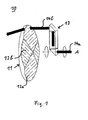
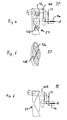
- Figures 7, 8a and 9a show further embodiments in which the lateral offset is corrected when it has a disturbing effect on high demands on the exact location of the desired measuring point.
- one side of the optical element 11 in the case shown here the rear side or the beam exit side, is designed as a spherical or aspherical surface.
- a spherically or aspherically formed surface element 16 is located on the rear side of the optical element 11.
- the radius of this sphere or asphere forms a positive focal length, which corresponds exactly to the distance to the measurement position. Since all parallel rays in If this focal point is bundled, all offset errors are corrected as well.
- the central area of the optical element 11 is flattened (FIGS. 8a, 8b) or recessed (FIGS. 9a, 9b).
- the flattening or recess is possible because only the area, which is penetrated by the laser beam, must have the wedge-shaped or spherical or aspherical shape.
- Figures 10 and 11 show a device 40 as another possible embodiment of the invention, with an optical element 41 which reflects the incident laser beam 14b.
- the individual segments of the optical element 41 have reflecting surfaces with the highest possible degree of reflection for laser wavelengths on the side facing the incident laser beam.
- deflection of the laser beam toward the axis of symmetry or rotation A can also take place here (FIG. 10), or a deflection away from the axis of symmetry or rotation A can take place (FIG. 11), or be combined by suitable segments both.
- the surface shape of the optical element 11 is more complex, i. no longer designed wedge-shaped with flat surfaces, but depending on the deflection spherical, aspherical, for example, parabolic, elliptical or helical.
- a u.U. existing and possibly disturbing beam deformation by such curved surfaces is not disturbing, especially in applications at a short distance and at relatively small deflection angles or even small beam diameters.
- this embodiment is used in cases where only deflection directions of a spatial axis, i. horizontal or vertical, are needed, which span a plane.
- a deflection by reflection on the optical element 11 is also possible here. That is, the optics for the deflection is not transparent in this case, but mirrored.
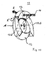
- FIG. 13 shows the optical element 11, which has segments 12a, 12b, 12c, 12d which are helically or conically shaped for deflecting the incident laser beam 14.
- the optical element 11 is designed annular, wherein the individual segments 12a, 12b, 12c, 12d, which are configured as a cone or helix, in the region of the circular path of the incident laser beam 14 are formed.
- the optical element 11 has a recess for weight reduction.
- each segment 12a, 12b, 12c, 12d is inclined in the circumferential direction with the surface of each segment 12a, 12b, 12c, 12d rising steadily in a circumferential direction. While the incident laser beam 14 passes over one of the segments 12a, it is constantly deflected by this segment in a direction R. When hitting the subsequent segment 12b, a change in direction of the deflected laser beam in the direction R 'takes place. This direction R 'in turn remains constant until the laser beam hits the next segment 12c due to the rotational movement, etc.
Landscapes
- Physics & Mathematics (AREA)
- General Physics & Mathematics (AREA)
- Optics & Photonics (AREA)
- Engineering & Computer Science (AREA)
- Transportation (AREA)
- Mechanical Engineering (AREA)
- Photometry And Measurement Of Optical Pulse Characteristics (AREA)
- Length Measuring Devices By Optical Means (AREA)
Description
- Die Erfindung betrifft eine Einrichtung zur Laserstrahlablenkung für optische Messsysteme gemäß dem Oberbegriff von Patentanspruch 1, sowie ein Verfahren zur Laserstrahlablenkung gemäß dem Oberbegriff von Patentanspruch 12.
- Messsysteme, die mit Laserstrahlen arbeiten, finden in verschiedenen Bereichen der Technik Anwendung. Ein besonderes Beispiel für derartige optische Messsysteme sind Luftdatensysteme, welche die Eigenschaften der Luft in einem gewissen Abstand In exakt definierten Messrichtungen erfassen und auswerten. Beispielsweise kann damit die Geschwindigkeit der Luftbewegung in allen drei Raumachsen, Lufttemperatur und Luftdruck gemessen werden. Die Luftdatensysteme können z.B. in einem Flugzeug oder Hubschrauber, einem Landfahrzeug, einem Satelliten oder auch stationär am Boden vorgesehen sein. Besondere Anwendung finden derartige Luftdatensysteme in der Luftfahrt, um z.B. in einem Flugzeug rechtzeitig Turbulenzen und andere wichtige Luftparameter erkennen zu können und entsprechende Steuerungen einzuleiten.
- Um den Laserstrahl in verschiedene Raumrichtungen zu lenken, werden in den bekannten Messsystemen zB. Scanner eingesetzt, die den Laserstrahl entlang einer Kreisbahn führen.
- In der Zeitschrift SPIE, Vol. 2956, Februar 1997, S. 76 ist ein Doppler Lidar zur Messung beschrieben, bei dem mit einem gepulsten Lichtstrahl und einem Scanmechanismus die Geschwindigkeitskomponenten der Luft gemessen werden. Durch den Scanmechanismus wird der Strahl über die verschiedenen Messpunkte geführt.
- In Applied Optics, Vol. 33, Nr. 27, S. 6467 aus dem Jahr 1994 wird ein Scanner für ein Luftdatenmesssystem beschrieben, bei dem ein rotierender Spiegel einen Laserstrahl ablenkt. Über feststehende Spiegel wird der abgelenkte Strahl durch ein Fenster des Messsystems nach außen geführt, um die Messdaten zu erfassen.
- Die Druckschrift WO 97/06462 zeigt ein optisches System, bei dem ein rotierendes optisches Element einen Laserstrahl seitlich versetzt und auf eine Kreisbahn bringt.
- In dem Dokument US 6,070,813 ist ein Verfahren zur Herstellung eines Gehäuses für Kraftstoffeinspritzeinrichtungen beschrieben. Dabei wird ein Laserstrahl mittels einer Optik seitlich von seiner Achse versetzt, wobei der versetzte Laserstrahl auf eine Linse trifft, durch die er fokussiert wird.
- Das Dokument GB 2 250 884 A zeigt einen Scanner, bei dem ein Laserstrahl mit kontinuierlich variierenden keilförmigen Segmenten in verschiedene Richtungen abgelenkt wird.
- In der Druckschrift GB 1 238 783 A ist eine Einrichtung zur Lichtstrahlabteitung beschrieben, bei der ein einfallender Lichtstrahl durch eine rotierende Scheibe in verschiedene Richtungen abgelenkt wird.
- Schließlich zeigt die Druckschrift WO 99/54082 ein Verfahren zum Ablenken eines Laserstrahls zur Materialbearbeitung, bei dem eine keilförmige Platte rotiert, um einen im Zentrum auftreffenden Laserstrahl in einer Kreisbahn zu führen.
- Bei den bekannten Laserstrahl-Umlenkeinrichtungen für Messsysteme besteht das Problem, dass die Pulswiederholfrequenzen nach oben hin begrenzt sind. Die bekannten Systeme sind nur für Dauerstrichlaser oder für Laser mit geringen Pulswiederholraten geeignet, da die mögliche Pulsfrequenz von der Scangeschwindigkeit abhängt Außerdem ist eine Synchronisation bzw. Triggerung eines jeden Laserpulses nötig. Hinzu kommt, dass die optischen Verluste möglichst gering gehalten werden sollen, und gleichzeitig hohe Leistungsdichten vorliegen sollen.
- Aufgabe der Erfindung ist es, eine Einrichtung und ein Verfahren zur Laserstrahlablenkung für optische Messsysteme anzugeben, welche für den Betrieb mit extrem leistungsstarken Lasern, wie beispielsweise Pulslasern mit hohen Leistungs- und Energiedichten sowie hohen Pulswiederholraten, geeignet sind und darüber hinaus geringe optische Verluste aufweisen.
- Diese Aufgabe wird gelöst durch die Einrichtung zur Laserstrahlablenkung für optische Messsysteme gemäß Patentanspruch 1, durch das Verfahren zur Laserstrahlablenkung in optischen Messsystemen gemäß Patentanspruch 12. Weitere vorteilhafte Merkmale, Aspekte und Details der Erfindung ergeben sich aus den abhängigen Ansprachen, der Beschreibung und den Zeichnungen.
- Die erfindungsgemäße Einrichtung zur Laserstrahleinrichtung umfasst ein optisches Element zur Ablenkung eines einfallenden Laserstrahls und eine Antriebseinheit zur Erzeugung einer Rotationsbewegung zwischen dem optischen Element und dem einfallenden Laserstrahl, um den Laserstrahl in verschiedene aufeinanderfolgende Richtungen abzulenken, wobei das optische Element mindestens zwei Segmente zur Ablenkung des einfallenden Laserstrahls um jeweils einen festen Ablenkwinkel umfasst und der Laserstrahl bei der Rotationsbewegung nacheinander auf die mindestens zwei Segmente trifft.
- Weiterhin umfasst die erfindungsgemäße Einrichtung eine rotierbare Umlenkeinheit, die dem optischen Element in Strahlrichtung vorgeschaltet und an das Antriebselement gekoppelt ist, um den Laserstrahl vor dem Auftreffen auf das optische Element seitlich zu versetzen bzw in eine Kreisbahn mit paralleler Strahlachse zu bringen. D.h., die Rotationsbewegung zwischen dem optischen Element und dem einfallenden Laserstrahl wird durch die Drehbewegung der Umlenkeinheit erzeugt Bevorzugt ist das optische Element feststehend ausgebildet bzw. fixiert.
- Dadurch ergibt sich, dass während einer definierten Zeitdauer immer ein exakt gleicher Ablenkwinkel im Raum geliefert wird und während dieser Zeit keine Winkelbewegung erfolgt. D.h., dass während der Zeitdauer, in der der Laserstrahl auf ein Segment trifft, die Richtung des abgelenkten Laserstrahls im Raum konstant ist. Trifft der Laserstrahl auf das nächste Segment, erfolgt eine Richtungsänderung des abgelenkten Laserstrahls, wobei die neue Richtung im Raum wiederum konstant ist, während der Laserstrahl durch das entsprechende Segment abgelenkt wird. Dies erklärt sich dadurch, dass der Laserstrahl beim Überstreichen eines Segments stets den gleichen Einfallswinkel auf die Segmentoberfläche aufweist Deshalb bleibt auch der Austrittswinkel bei diesem Segment konstant.
- Dadurch kann bei der Messung insbesondere eine hohe Pulsrate erzielt werden, d.h. es können Pulslaser mit beliebig hohen Pulswiederholraten verwendet werden. Somit können extrem leistungsstarke Laser, beispielsweise Pulslaser mit hohen Leistungs- und Energiedichten, in optischen Messsystemen eingesetzt werden. Darüberhinaus wird ein sehr hoher Wirkungsgrad erzielt da die optischen Verluste mit der erfindungsgemäßen Einrichtung extrem gering sind. Es ergibt sich weiterhin eine sehr hohe Richtungsgenauigkeit und Richtungsstabilität des abgelenkten Laserstrahls sowie eine weitgehende Temperaturunabhängigkeit. Die erfindungsgemäße Einrichtung kann sehr stabil gegenüber Vibrationen, Erschütterungen und Beschleunigungen aufgebaut werden und ist darüber hinaus sehr kompakt mit einem geringen Volumen, was für Anwendungen in der Luft- und Raumfahrt besonders vorteilhaft ist.
- Die erfindungsgemäße Einrichtung kann nahezu verschleißfrei bzw. mit einer hohen Lebensdauer der Lager realisiert werden und sie besteht nur aus wenigen Bauteilen, weshalb sie besonders kostengünstig ist.
- Darüberhinaus können mit nur einem Laser mehrere Messpositionen, deren Anzahl z.B. zwischen 2 und etwa 100 liegen, nahezu zeitgleich erfasst werden. Dabei kann die Abtastfrequenz der einzelnen Messpositionen mehrere hundert Hertz betragen. Totzeiten, bei denen die Einheit auf Grund von Schaltvorgängen aussetzt, werden vermieden.
- Vorteilhafterweise ist das optische Element derart angeordnet, dass der einfallende Laserstrahl bei der Rotationsbewegung auf der Oberfläche des optischen Elements eine Kreisbahn ausführt.
- Das optische Element ist vorzugsweise scheiben- oder ringförmig ausgestaltet und die einzelnen Segmente des optischen Elements sind bevorzugt keilförmig ausgebildet, wobei der Keilwinkel jedes Segments dessen Ablenkwinkel definiert.
- Vorteilhafterweise haben die Segmente des optischen Elements Oberflächen, die gegenüber der Strahlachse des einfallenden Laserstrahls geneigt sind, wobei die Neigungswinkel der Oberfläche jedes Segments zusammen mit der Brechzahl des optischen Materials dessen Ablenkwinkel definiert. Insbesondere behält während des Auftreffens des Laserstrahls auf ein Segment der abgelenkte Laserstrahl eine konstante Richtung im Raum.
- Bevorzugt sind die Segmente derart gestaltet, dass der einfallende Laserstrahl zur Rotationsachse bzw. Symmetrieachse hin abgelenkt wird. Dadurch kann das Fenster, aus dem der Laserstrahl bei einem entsprechenden optischen Messsystem austritt, besonders klein gehalten werden. Es ist aber auch möglich, dass die Segmente den einfallenden Laserstrahl von der Rotationsachse weg ablenken.
- Beispielsweise sind die Segmente derart gestaltet, dass der jeweils einfallende Laserstrahl von jedem Segment in eine andere definierte Richtung abgelenkt wird. Es können aber auch mehrere Segmente gleich ausgestaltet sein, um während der Rotationsbewegung den Laserstrahl mehrmals in ein und dieselbe definierte Richtung abzulenken.
- Vorteilhaft ist zwischen zwei aneinandergrenzenden Segmenten ein Übergangsbereich vorhanden, der eine Richtungsänderung des Laserstrahls ohne Strahlunterbrechung ermöglicht. Dadurch kann bei der Messung ein Überblenden von einem Messpunkt bzw. einer Messrichtung zu einem anderen Messpunkt bzw. einer anderen Messrichtung erfolgen.
- Besonders vorteilhaft ist es, wenn das optische Element an einer Seite, beispielsweise an der Rückseite, sphärisch oder asphärisch ausgebildet ist bzw. ein sphärisch oder asphärisch ausgebildetes Flächenelement mit einer positiven Brennweite aufweist. Dadurch kann ein Versatz des auf das optische Element einfallenden Laserstrahls während der Kreisbewegung des Laserstrahls an einem gewünschten Messpunkt korrigiert werden, so dass die Lage der Messposition besonders genau eingehalten werden kann.
- Bevorzugt ist das optische Element in einem Teilbereich, der nicht zur Strahlablenkung genutzt wird, abgeflacht bzw. als ebene Fläche ausgebildet, oder es weist in dem Teilbereich eine Aussparung auf. Dadurch kann eine weitere Gewichtsreduzierung und Miniaturisierung der Einrichtung erreicht werden.
- Das optische Element ist bevorzugt transparent, wobei der jeweilige Ablenkwinkel durch Lichtbrechung in Segmenten erzeugt wird. Es ist aber auch möglich, das optische Element reflektierend auszugestalten, wobei der jeweilige Ablenkwinkel durch Reflexion an den Segmenten bzw. Segmentoberflächen erzeugt wird.
- Die Verweildauer des abgelenkten Laserstrahls in einer definierten Raumrichtung kann in Abhängigkeit vom Winkelbereich des jeweiligen Segments und der Rotationsfrequenz bestimmt werden. Dadurch ergibt sich eine besonders hohe Flexibilität hinsichtlich der Art und Weise der Messung.
- Bevorzugt weisen die Segmente an einer Seite eine sphärische oder asphärische Oberfläche auf. Dadurch kann eine Korrektur eines parallelen Strahlversatzes erreicht werden.
- Bevorzugt sind die Segmente derart gestaltet, dass die Strahlablenkung zur Rotationsachse hin erfolgt Dadurch kann das Austrittsfenster für den Laserstrahl besonders klein gehalten werden.
- Vorteilhafterweise ist das erfindungsgemäße optische Element in einer erfindungsgemäßen Einrichtung zur Laserstrahlablenkung vorgesehen bzw. einsetzbar. Vorteile und Merkmale des erfindungsgemäßen optischen Elements gelten auch für die erfindungsgemäße Laserstrahlablenkeinrichtung und umgekehrt.
- Gemäß einem weiteren Aspekt der Erfindung wird ein Verfahren zur Laserstrahlablenkung angegeben, bei dem ein einfallender Laserstrahl durch ein optisches Element nacheinander in mindestens zwei unterschiedliche Richtungen abgelenkt wird, wobei eine vorgeschaltete Umlenkeinheit rotiert, und wobei der zur Rotationsachse seitlich parallel versetzt einfallende Laserstrahl während einer Rotation jeweils für eine Zeitdauer t auf mindestens zwei Segmente des optischen Elements trifft und jedes Segment den Laserstrahl während der Zeitdauer t in genau eine definierte Richtung ablenkt, wobei die Richtung des abgelenkten Laserstrahls während der Zeitdauer t konstant ist.
- Durch das erfindungsgemäße Verfahren können insbesondere extrem leistungsstarke Laser bzw. Pulslaser mit beliebig hohen Pulswiederholraten in optischen Messsystemen verwendet werden und die Abtastfrequenz der einzelnen Messpositionen kann dabei beispielsweise mehrere hundert Hertz betragen. Im Übrigen gelten die Vorteile und Merkmale, die in Bezug auf die erfindungsgemäße Einrichtung und das erfindungsgemäße optische Element genannt sind, auch für das erfindungsgemäße Verfahren.
- Vorteilhafterweise wird das Verfahren mit einer erfindungsgemäßen Einrichtung durchgeführt.
- Nachfolgend wird die Erfindung anhand der Figuren beispielhaft beschrieben, in denen
- Fig. 1
- eine Laserstrahlablenkeinrichturig gemäß einer bevorzugten Ausführungsform der Erfindung schematisch in perspektivischer Darstellung zeigt;
- Fig. 2
- eine Schnittansicht der in Fig. 1 gezeigten Einrichtung schematisch darstellt;
- Fig. 3a - 3d
- Vorderansichten von erfindungsgemäßen optischen Elementen verschiedener bevorzugter Ausführungsformen schematisch darstellen;
- Fig. 4
- eine schematische Seitenansicht der erfindungsgemäßen Einrichtung gemäß einer weiteren bevorzugten Ausführungsform zeigt;
- Fig. 5
- eine perspektivische Darstellung des in Fig. 4 verwendeten optischen Elements schematisch darstellt;
- Fig. 6
- eine andere Ausführungsform der erfindungsgemäßen Laserstrahlablenkeinrichtung in einer Seitenansicht schematisch zeigt, bei der der Laserstrahl von der Symmetrieachse weg abgelenkt wird;
- Fig. 7
- eine besonders bevorzugte Ausführungsform der erfindungsgemäßen Einrichtung mit einem gekrümmten Flächenelement in einer Seitenansicht schematisch zeigt;
- Fig. 8a und 8b
- eine weitere bevorzugte Ausführungsform der Erfindung mit einem abgeflachten optischen Element schematisch zeigen;
- Fig. 9a und 9b
- eine noch weitere bevorzugte Ausführungsform der Erfindung mit einem an einer Seite ausgesparten optischen Element zeigen;
- Fig. 10
- eine erfindungsgemäße Einrichtung mit einem reflektierenden optischen Element in einer Seitenansicht schematisch zeigt;
- Fig. 11
- eine erfindungsgemäße Einrichtung mit einem reflektierenden optischen Element und Strahlablenkung von der Symmetrieachse weg in einer Seitenansicht schematisch zeigt;
- Fig. 12
- eine Schnittansicht einer erfindungsgemäßen Laserstrahlablenkeinrichtung mit einem optischen Element schematisch zeigt; und
- Fig. 13
- ein optisches Element gemäß einer besonders bevorzugten Aus führungsform der Erfindung schematisch in perspektivischer Darstellung zeigt.
- Fig. 1 zeigt eine erfindungsgemäße Laserablenkeinheit bzw. -einrichtung 10 zur Laserstrahlablenkung für optische Messsysteme gemäß einer bevorzugten Ausführungsform der Erfindung. Die Einrichtung 10 umfasst ein optisches Element 11 mit mehreren Segmenten 12a, 12b, die keilförmig gestaltet sind. Das optische Element 11 ist in Form einer runden Scheibe ausgestaltet, wobei die einzelnen Segmente 12a, 12b der Scheibe in radialer Richtung geneigte Oberflächen aufweisen.
- Eine Umlenkeinheit 13 in Form einer rotierbaren Optik ist dem feststehenden optischen Element 11 vorgeschaltet und dient dazu, einen Laserstrahl 14a seitlich zu versetzen und den versetzten Laserstrahl 14b in eine Kreisbewegung zu bringen, wobei die Strahlachse parallel zur ursprünglichen Strahlachse gerichtet ist. Somit beschreibt der seitlich versetzte Laserstrahl 14b nach Durchlaufen der rotierenden Umlenkeinheit 13 die Mantelfläche eines Zylinders bzw. eine Kreisbewegung in Zylinderform. Die Form des optischen Elements 11, das beispielsweise auch als ringförmiger Scheibenausschnitt ausgestaltet sein kann und vorzugsweise auf seiner Vorderseite bzw. Strahleintrittsseite in die einzelnen Segmente 12a, 12b unterteilt ist, ist im Seitenschnitt für jedes dieser Segmente 12a, 12b keilförmig. Dabei besitzt jedes Segment 12a, 12b einen eigenen Keilwinkel mit eigener Ausrichtung.
- Fig. 2 zeigt die erfindungsgemäße Einrichtung 10 im Seitenschnitt. Die Keilform der einzelnen Segmente 12a, 12b bewirkt, dass der einfallende Laserstrahl 14b, der jeweils innerhalb eines Segments auf das optische Element 11 trifft, an den Oberflächen der keilförmigen Segmente 12a, 12b nacheinander in die verschiedenen gewünschten Richtungen gebrochen wird. Jede durch ein einzelnes Segment 12a, 12b verursachte Richtung des Laserstrahls wird beim Wandern des einfallenden Laserstrahls 14b über eine Segmentfläche exakt beibehalten. Die einzelnen Keile bzw. Segmente 12a, 12b sind in diesem Beispiel Prismen.
- Die Umlenkeinheit 13, die rotierend gelagert ist und durch eine in den Figuren nicht dargestellte Antriebseinheit in Rotation versetzt wird, enthält zur Strahlumlenkung Spiegel, beispielsweise metallischer oder dielektrischer Art, als Umlenkflächen, an denen der Laserstrahl 14a durch Reflexion seitlich versetzt wird. Es können aber auch Prismen unter Verwendung der Totalreflexion an den Umlenkflächen verwendet werden. Bei Verwendung von Prismen kann die rotierende Optik bzw. Umlenkeinheit 13 auch als transparenter Monolith ausgebildet sein.
- Nach Durchlaufen der im Betrieb rotierenden Umlenkeinheit 13 trifft der zylindrisch kreisende Laserstrahl 14b auf das feststehende, optisch transparente optische Element 11, dessen spezielle Form den Laserstrahl in die gewünschte Richtung bricht.
- Die Figuren 3a - 3d zeigen das optische Element 11 in verschiedenen Ausführungsformen in einer Ansicht von vorne.
- In Fig. 3a enthält das als runde Scheibe ausgebildete optische Element 11 an seiner Strahleintrittsseite bzw. Vorderseite oder Rückseite eine Fläche, die in vier Teilsegmente 12a, 12b, 12c, 12d unterteilt ist. Der im Wesentlichen senkrecht auf die Vorderseite des optischen Elements 11 auftreffende Laserstrahl 14b beschreibt eine Kreisbahn 15 im Randbereich des optischen Elements 11, wobei der einfallende Laserstrahl 14b nacheinander auf die einzelnen Segmente 12a, 12b, 12c, 12d trifft und durch diese in verschiedene Richtungen im Raum abgelenkt wird. Dabei hat jedes Segment 12a, 12b, 12c, 12d einen festen Ablenkwinkel im Raum, so dass der abgelenkte Laserstrahl 14c während einer Zeitdauer t in seiner Raumrichtung konstant bleibt, d.h. so lange der einfallende Laserstrahl 14b von dem entsprechenden Segment abgelenkt wird.
- In der Figur 3b ist das optische Element 11 gleichmäßig in zwei Teilsegmente 12a, 12b unterteilt, während es in Fig. 3c gleichmäßig in drei Teilsegmente 12a, 12b, 12c unterteilt ist.
- In Fig. 3d ist das optische Element 11 mit einer Unterteilung in Segmente 12a, 12b, 12c gezeigt, die jeweils einen unterschiedlichen Winkelbereich des optischen Elements 11 einnehmen. Dadurch wird bei konstanter Kreisgeschwindigkeit bzw. Rotationsgeschwindigkeit eine unterschiedliche Verweildauer des abgelenkten Laserstrahls in den einzelnen Messpositionen erreicht. Der Segmentwinkel α eines Segments 12a, 12b, 12c, 12d legt zusammen mit der Rotationsfrequenz F in Hertz die Verweildauer bzw. Messzeit Tm in Sekunden pro Richtung fest. Dabei gilt:

- Das Umschalten von einer Ablenkungsrichtung zur nächsten erfolgt nicht spontan, sondern entspricht einem Überblenden. Die Überblenddauer Tü hängt vom Laserstrahldurchmesser DL, von der Rotationsfrequenz F in Hertz und vom Durchmesser der Kreisbahn DK ab, den der Laserstrahl 14b auf dem optischen Element 11 beschreibt. Dabei gilt näherungsweise folgender Zusammenhang:

- Die Anzahl der Scheiben- oder Ringsegmente bestimmt die Anzahl der Messpositionen der optischen Messeinrichtung, in der die Laserablenkungseinrichtung verwendet wird. Beispielsweise müssen bei zwei Positionen demnach mindestens zwei Segmente ausgebildet sein, bei drei Positionen mindestens drei, usw..
- Der Ablenkwinkel jedes Segments 12a, 12b, 12c, 12d hängt nur vom Keilwinkel und der Neigung des keilförmigen Segments ab. Daher ist die Genauigkeit des Ablenkwinkels nur durch Fertigungstoleranzen bestimmt und verhält sich zeitlich stabil. Bei der Realisierung kann eine gegebenenfalls durch Lagerspiel vorhandene Winkelvariation der rotierenden Elemente durch geeignete Auswahl der Lager vernachlässigbar klein gehalten werden.
- In Fig. 4 ist eine Einrichtung zur Strahlumlenkung 20 gemäß einer weiteren bevorzugten Ausführungsform der Erfindung gezeigt, mit einem optischen Element 21, bei dem mehrere Segmente 12a, 12b eine Ablenkung in der gleichen Richtung bewirken. Das optische Element 21 ist in Fig. 5 schematisch in perspektivischer Darstellung gezeigt. Bei dieser Ausführungsform erfolgt während einer Umdrehung ein zweimaliges Ablenken des Laserstrahls in dieselbe Richtung.
- Fig. 6 zeigt eine weitere Ausführungsform der Erfindung mit einer Einrichtung zur Strahlablenkung 30, deren optisches Element 31 eine Strahlablenkung von der Symmetrie- bzw. Rotationsachse A weg bewirkt. Demgegenüber hat jedoch die in den vorhergehenden Figuren gezeigte Strahlablenkung zur Rotationsachse A hin den Vorteil, dass der für die Laserstrahlung genutzte Raum im Strahlengang nach der Optik kleiner gehalten werden kann um beispielsweise ein kleineres optisches Austrittsfenster zu ermöglichen. Dies ist insbesondere auch in Fahrzeugen oder Flugzeugen vorteilhaft.
- Durch die Keilform der einzelnen Segmente 12a, 12b, 12c, 12d durchläuft der Laserstrahl unterschiedliche Dicken des jeweiligen Segments. Dies führt zu einem seitlichen Versatz des abgelenkten Laserstrahls, wobei der Versatz in etwa der Segmentbreite am Ort der Kreisbewegung entspricht. Bei diesem Versatz bleibt der abgelenkte Laserstrahl parallel.
- Die Figuren 7, 8a und 9a zeigen weitere Ausführungsformen, bei denen der seitliche Versatz korrigiert wird, wenn er sich bei hoher Anforderung an die exakte Lage des gewünschten Messpunkts störend auswirkt. Dabei ist eine Seite des optischen Elements 11, im hier gezeigten Fall die Rückseite bzw. Strahlaustrittsseite, als sphärische oder asphärische Fläche ausgebildet. Zu diesem Zweck befindet sich auf der Rückseite des optischen Elements 11 ein sphärisch oder asphärisch ausgebildetes Flächenelement 16. Um eine exakte Versatzkorrektur zu erreichen, bildet der Radius dieser Sphäre oder Asphäre eine positive Brennweite, die genau dem Abstand zur Messposition entspricht. Da alle parallelen Strahlen in diesem Brennpunkt gebündelt werden, werden auch alle Versatzfehler hierdurch korrigiert.
- Bei den in Figuren 8a, 8b, 9a, 9b gezeigten Ausführungsformen ist der zentrale Bereich des optischen Elements 11 abgeflacht (Figuren 8a, 8b) bzw. ausgespart (Figuren 9a, 9b). Hierdurch wird eine weitere Gewichtsreduzierung und Miniaturisierung der Einrichtung erreicht. Die Abflachung bzw. Aussparung ist möglich, da nur der Bereich, der vom Laserstrahl durchdrungen wird, die keilförmige bzw. sphärische oder asphärische Form besitzen muss.
- Die Figuren 10 und 11 zeigen eine Einrichtung 40 als weitere mögliche Ausführungsform der Erfindung, mit einem optischen Element 41, das den einfallenden Laserstrahl 14b reflektiert. Dazu haben die einzelnen Segmente des optischen Elements 41 spiegelnde Oberflächen mit einem möglichst hohen Reflexionsgrad für Laserwellenlängen auf der dem einfallenden Laserstrahl zugewandten Seite. Ebenso wie bei den oben beschriebenen Ausführungsformen kann auch hier eine Ablenkung des Laserstrahls zur Symmetrie- bzw. Rotationsachse A hin erfolgen (Fig. 10), oder auch eine Ablenkung von der Symmetrie- bzw. Rotationsachse A weg erfolgen (Fig. 11), oder durch geeignete Segmente beides kombiniert werden.
- Bei der in Fig. 12 dargestellten Ausführungsform ist die Oberflächenform des optischen Elements 11 komplexer, d.h. nicht mehr nur keilförmig mit planen Flächen ausgeführt, sondern je nach Ablenkrichtung sphärisch, asphärisch, beispielsweise auch parabolisch, elliptisch oder wendelförmig. Eine u.U. vorhandene und ggf. störende Strahlverformung durch derartige gekrümmte Oberflächen ist insbesondere bei Anwendungen in kurzer Entfernung und bei relativ kleinen Ablenkwinkeln oder auch kleinen Strahldurchmessern nicht störend. Vorzugsweise wird diese Ausführungsform in Fällen verwendet, in denen nur Ablenkrichtungen einer Raumachse, d.h. horizontal oder vertikal, benötigt werden, die eine Ebene aufspannen.
- Ähnlich wie in den oben beschriebenen Ausführungsformen ist auch hier eine Ablenkung durch Reflexion auf dem optischen Element 11 möglich. D.h., die Optik zur Ablenkung ist in diesem Fall nicht transparent, sondern verspiegelt.
- Fig. 13 zeigt das optische Element 11, das zum Ablenken des einfallenden Laserstrahls 14 wendelartig oder kegelartig ausgeformte Segmente 12a, 12b, 12c, 12d aufweist. Das optische Element 11 ist ringförmig gestaltet, wobei die einzelnen Segmente 12a, 12b, 12c, 12d, die als Kegel oder Wendel ausgestaltet sind, im Bereich der Kreisbahn des auftreffenden Laserstrahls 14 ausgebildet sind. In seinem zentralen Bereich 17 hat das optische Element 11 eine Aussparung zur Gewichtsreduzierung.
- Die dem einfallenden Laserstrahl zugewandte Seite jedes Segments 12a, 12b, 12c, 12d ist in Umfangsrichtung geneigt, wobei die Oberfläche jedes Segments 12a, 12b, 12c, 12d in einer Umfangsrichtung stetig ansteigt. Während der einfallende Laserstrahl 14 eines der Segmente 12a überstreicht, wird er durch dieses Segment konstant in eine Richtung R abgelenkt. Beim Auftreffen auf das nachfolgende Segment 12b erfolgt eine Richtungsänderung des abgelenkten Laserstrahls in die Richtung R'. Diese Richtung R' bleibt wiederum konstant, bis der Laserstrahl aufgrund der Rotationsbewegung auf das nächste Segment 12c trifft, usw..
Claims (13)
- Einrichtung zur Laserstrahlablenkung für optische Messsysteme, mit einem optischen Element (11;21: 31; 41) zur Ablenkung eines einfallenden Laserstrahls (14; 14b); und
einer Antriebseinheit zur Erzeugung einer Rotationsbewegung zwischen dem optischen Element (11; 21; 31; 41) und dem einfallenden Laserstrahl (14; 14b):
gekennzeichnet durch
eine rotierbare Umlenkeinheit (13), die dem optischen Element (11; 21; 31; 41) in Strahlrichtung vorgeschaltet und an die Antriebseinheit gekoppelt ist, um den einfallenden Laserstrahl (14a) vor seinem Auftreffen auf das optische Element (11; 21: 31; 41) seitlich parallel zu versetzen und in eine Kreisbahn zu bringen;
wobei die rotierbare Umlenkeinheit derart angeordnet ist, dass der Laserstrahl (14; 14b) die Kreisbahn auf der Oberfläche des optischen Elements (11; 21; 31; 41) ausführt;
und wobei das optische Element (11; 21; 31; 41) mindestens zwei Segmente (12a, 12b, 12c, 12d) umfasst, die derart gestaltet sind, dass der auftreffende Laserstrahl (14; 14b) durch die Segmente (12a, 12b, 12c, 12d) nacheinander in verschiedene definierte Richtungen (R, R) abgelenkt wird, wobei während des Auftreffens des Laserstrahls (14; 14b) auf das jeweilige Segment (12a, 12b, 12c, 12d) die Richtung (R. R) des abgelenkten Laserstrahls konstant ist. - Einrichtung nach Anspruch 1, dadurch gekennzeichnet, dass das optische Element (11; 21; 31; 41) Scheiben- oder ringförmig ausgestaltet ist.
- Einrichtung nach einem der vorhergehenden Ansprüche, dadurch gekennzeichnet, dass die Segmente (12a, 12b, 12c, 12d) des optischen Elements (11; 21; 31; 41) ebene Oberflächen aufweisen, die gegenüber der Strahlachse des einfallenden Laserstrahls geneigt sind, wobei der Neigungswinkel jedes Segments (12a, 12b, 12c, 12d) dessen Ablenkwinkel definiert.
- Einrichtung nach einem der vorhergehenden Ansprüche, dadurch gekennzeichnet, dass die Segmente (12a, 12b, 12c, 12d) derart gestaltet sind, dass der einfallende Laserstrahl (14; 14b) zur Rotationsachse (A) hin abgelenkt wird.
- Einrichtung nach einem der vorhergehenden Ansprüche, dadurch gekennzeichnet, dass mehrere Segmente (12a, 12b. 12c. 12d) gleich ausgestaltet sind, um während der Rotationsbewegung den Laserstrahl (14; 14b) mehrmals in ein und dieselbe definierte Richtung abzulenken.
- Einrichtung nach einem der vorhergehenden Ansprüche, dadurch gekennzeichnet, dass zwischen zwei aneinandergrenzenden Segmenten (12a, 12b, 12c, 12d) ein Obergangsbereich vorhanden ist, der eine Richtungsänderung des Laserstrahls ohne Strahlunterbrechung ermöglicht.
- Einrichtung nach einem der vorhergehenden Ansprüche, dadurch gekennzeichnet, dass das optische Element (11) an einer Seite ein sphärisch oder asphärisch ausgebildetes Flächenelement (16) mit einer positiven Brennweite aufweist.
- Einrichtung nach einem der vorhergehenden Ansprüche, dadurch gekennzeichnet, dass das optische Element (11; 21; 31; 41) in einem nicht zur Strahlablenkung genutzten Teilbereich abgeflacht ist oder eine Aussparung aufweist.
- Einrichtung nach einem der vorhergehenden Ansprüche, dadurch gekennzeichnet, dass das optische Element (11; 21; 31; 41) transparent ist, wobei der jeweilige Ablenkwinkel durch Lichtbrechung in den Segmenten (12a, 12b, 12c, 12d) erzeugt wird.
- Einrichtung nach einem der vorhergehenden Ansprüche, dadurch gekennzeichnet, dass das optische Element (11; 21; 31; 41) reflektierend ist, wobei der jeweilige Ablenkwinkel durch Reflexion an den Segmenten (12a, 12b, 12c, 12d) erzeugt wird.
- Einrichtung nach einem der vorhergehenden Ansprüche, dadurch gekennzeichnet, dass die Verweildauer des abgelenkten Laserstrahls in einer definierten Raumrichtung in Abhängigkeit vom Winkelbereich des jeweiligen Segments (12a, 12b, 12c, 12d) und der Rotationsfrequenz bestimmt ist.
- Verfahren zur Laserstrahlablenkung in optischen Messsystemen, bei dem ein einfallender Laserstrahl (14; 14b) durch ein optisches Element (11; 21; 31; 41) nacheinander in mindestens zwei unterschiedliche Richtungen (R, R') abgelenkt wird, wobei
der Laserstrahl (14; 14b) jeweils für eine Zeitdauer (t) auf mindestens zwei Segmente (12a, 12b, 12c, 12d) des optischen Elements (11;21;31;41) trifft,
wobei jedes Segment (12a, 12b, 12c, 12d) den Laserstrahl (14;14b) während der Zeitdauer (t) in genau eine definierte Richtung (R, R') ablenkt,
dadurch gekennzeichnet, dass
der Laserstrahl (14; 14b) vor dem Auftreffen auf das optische Element (11; 21; 31; 41) mittels einer rotierenden Umlenkeinheit (13) seitlich parallel versetzt wird und eine Kreisbahn ausführt wobei die Strahlachse parallel zur ursprünglichen Strahlachse gerichtet ist, und wobei die Richtung (R, R) des abgelenkten Laserstrahls während der Zeitdauer (t) konstant ist. - Verfahren nach Anspruch 12, dadurch gekennzeichnet, dass es mit einer Einrichtung nach einem der Ansprüche 1 bis 11 durchgeführt wird.
Applications Claiming Priority (3)
| Application Number | Priority Date | Filing Date | Title |
|---|---|---|---|
| DE10228899A DE10228899A1 (de) | 2002-06-27 | 2002-06-27 | Einrichtung und Verfahren zur Laserstrahlablenkung für optische Messsysteme und optisches Element |
| DE10228899 | 2002-06-27 | ||
| PCT/DE2003/001893 WO2004003626A1 (de) | 2002-06-27 | 2003-06-07 | Einrichtung und verfahren zur laserstrahlablenkung für optische messsysteme |
Publications (2)
| Publication Number | Publication Date |
|---|---|
| EP1516221A1 EP1516221A1 (de) | 2005-03-23 |
| EP1516221B1 true EP1516221B1 (de) | 2006-03-15 |
Family
ID=29761501
Family Applications (1)
| Application Number | Title | Priority Date | Filing Date |
|---|---|---|---|
| EP03737934A Expired - Lifetime EP1516221B1 (de) | 2002-06-27 | 2003-06-07 | Einrichtung und verfahren zur laserstrahlablenkung für optische messsysteme |
Country Status (6)
| Country | Link |
|---|---|
| US (1) | US7123394B2 (de) |
| EP (1) | EP1516221B1 (de) |
| AT (1) | ATE320615T1 (de) |
| AU (1) | AU2003245857A1 (de) |
| DE (2) | DE10228899A1 (de) |
| WO (1) | WO2004003626A1 (de) |
Families Citing this family (18)
| Publication number | Priority date | Publication date | Assignee | Title |
|---|---|---|---|---|
| FR2870942B1 (fr) | 2004-05-25 | 2006-08-25 | Airbus France Sas | Systeme de mesure anticipee d'une turbulence en amont d'un aeronef |
| WO2006020109A2 (en) * | 2004-07-16 | 2006-02-23 | Hills, Inc. | Forming shaped fiber fabrics |
| JP2006243538A (ja) * | 2005-03-04 | 2006-09-14 | Nidec Sankyo Corp | 光ビーム走査装置 |
| EP1698930A3 (de) * | 2005-03-04 | 2007-04-11 | Nidec Sankyo Corporation | Lichtstrahlabtastvorrichtung |
| US20060279827A1 (en) * | 2005-06-10 | 2006-12-14 | Optical Physics Company | Wide angle beam director |
| JP2007155467A (ja) * | 2005-12-05 | 2007-06-21 | Nidec Sankyo Corp | 光ビーム走査装置 |
| US7768686B2 (en) * | 2007-02-05 | 2010-08-03 | Raytheon Company | Light-beam-scanning system utilizing counter-rotating prism wheels |
| TWM324785U (en) * | 2007-04-16 | 2008-01-01 | Young Optics Inc | Illumination system |
| PL2248073T3 (pl) | 2008-02-05 | 2016-10-31 | Generator wzorca optycznego stosujący segmenty aksikonu | |
| FR2990522B1 (fr) * | 2012-05-09 | 2015-02-06 | Ideoptics | Systeme optique de deflexion |
| US11353359B1 (en) | 2013-03-14 | 2022-06-07 | Wavefront Research, Inc. | Pupil division multiplexed imaging systems |
| US9733121B1 (en) * | 2013-03-14 | 2017-08-15 | Wavefront Research, Inc. | Pupil division multiplexed imaging systems |
| EP3224665B1 (de) | 2014-11-24 | 2018-08-22 | Philips Lighting Holding B.V. | Beleuchtungsvorrichtung und beleuchtungssystem |
| DE102015105613B4 (de) | 2015-04-13 | 2023-08-31 | Carl Zeiss Industrielle Messtechnik Gmbh | Auflicht-Beleuchtung für variablen Arbeitsabstand |
| DE102016102971B4 (de) * | 2016-02-19 | 2021-02-11 | Carl Zeiss Industrielle Messtechnik Gmbh | Linseneinrichtung für variablen Arbeitsabstand, Beleuchtungsbaugruppe, Koordinatenmessgerät und Verfahren |
| DE102018204858B4 (de) * | 2018-03-29 | 2023-12-07 | Robert Bosch Gmbh | LiDAR-System |
| US20220113429A1 (en) * | 2020-10-09 | 2022-04-14 | Yandex Self Driving Group Llc | Lidar systems and methods |
| DE102023110581B3 (de) | 2023-04-25 | 2024-07-04 | Deutsches Zentrum für Luft- und Raumfahrt e.V. | Optisches Messsystem zur Erfassung von Umgebungsparametern in einer Umgebung |
Family Cites Families (17)
| Publication number | Priority date | Publication date | Assignee | Title |
|---|---|---|---|---|
| DE1803609B2 (de) * | 1968-10-17 | 1971-07-15 | Vorrichtung zum zeilenversatz bei opto elektronischen abtast geraeten | |
| US3746421A (en) * | 1971-10-27 | 1973-07-17 | Barnes Eng Co | Multiple line rotating polygon |
| US3881802A (en) * | 1974-04-18 | 1975-05-06 | Bendix Corp | Wedge-prism optical scanner |
| GB1521931A (en) * | 1976-01-31 | 1978-08-16 | Ferranti Ltd | Optical apparatus |
| US4544228A (en) * | 1982-09-14 | 1985-10-01 | Spectra-Physics, Inc. | Scanning method using a rotating prism |
| DE3939577A1 (de) * | 1989-11-30 | 1991-06-06 | Fraunhofer Ges Forschung | Vorrichtung zum ablenken des lichtstrahls |
| GB9001509D0 (en) * | 1990-01-23 | 1990-03-21 | Davy Mckee Poole | An optical imaging device for guiding a robot |
| JP3034637B2 (ja) * | 1990-08-28 | 2000-04-17 | 株式会社リコー | 光偏向素子および光走査装置 |
| GB2250884B (en) * | 1990-12-07 | 1995-05-10 | Philips Electronic Associated | Optical image sensing systems |
| GB2256937A (en) * | 1991-06-21 | 1992-12-23 | Gec Ferranti Defence Syst | Optical scanner |
| FR2693292B1 (fr) * | 1992-07-01 | 1994-09-16 | Reflexion Plus | Lecteur omnidirectionnel de vignettes de code à barre, à zone de lecture agrandie. |
| WO1997006462A1 (en) * | 1995-08-09 | 1997-02-20 | Minnesota Mining And Manufacturing Company | Rotating optical system for laser machining apparatus |
| DE19645573A1 (de) * | 1996-11-05 | 1998-05-07 | Bodenseewerk Geraetetech | Rundumbeobachtungsgerät |
| DE19817851C1 (de) | 1998-04-22 | 1999-10-28 | Lpkf Laser & Electronics Gmbh | Verfahren zum Ablenken eines Laserstrahls |
| US6070813A (en) * | 1998-08-11 | 2000-06-06 | Caterpillar Inc. | Laser drilled nozzle in a tip of a fuel injector |
| EP1133707A4 (de) * | 1998-10-26 | 2002-01-09 | Herzel Laor | 1xN REFLEKBORSCHALTER |
| US6343767B1 (en) * | 1999-03-03 | 2002-02-05 | Raytheon Company | Missile seeker having a beam steering optical arrangement using risley prisms |
-
2002
- 2002-06-27 DE DE10228899A patent/DE10228899A1/de not_active Withdrawn
-
2003
- 2003-06-07 DE DE50302672T patent/DE50302672D1/de not_active Expired - Lifetime
- 2003-06-07 AT AT03737934T patent/ATE320615T1/de not_active IP Right Cessation
- 2003-06-07 AU AU2003245857A patent/AU2003245857A1/en not_active Abandoned
- 2003-06-07 EP EP03737934A patent/EP1516221B1/de not_active Expired - Lifetime
- 2003-06-07 WO PCT/DE2003/001893 patent/WO2004003626A1/de not_active Ceased
-
2004
- 2004-12-27 US US11/020,116 patent/US7123394B2/en not_active Expired - Fee Related
Also Published As
| Publication number | Publication date |
|---|---|
| US7123394B2 (en) | 2006-10-17 |
| DE10228899A1 (de) | 2004-01-22 |
| DE50302672D1 (de) | 2006-05-11 |
| AU2003245857A1 (en) | 2004-01-19 |
| EP1516221A1 (de) | 2005-03-23 |
| WO2004003626A1 (de) | 2004-01-08 |
| ATE320615T1 (de) | 2006-04-15 |
| US20050225763A1 (en) | 2005-10-13 |
Similar Documents
| Publication | Publication Date | Title |
|---|---|---|
| EP1516221B1 (de) | Einrichtung und verfahren zur laserstrahlablenkung für optische messsysteme | |
| EP3350615B1 (de) | Lidarsensor | |
| EP3673291B1 (de) | Sendeeinrichtung mit einem durch ein kollimierendes abdeckelement überdeckten scanspiegel | |
| DE4328894C2 (de) | Laserbearbeitungsvorrichtung und zugehöriges Verfahren | |
| DE4438368C2 (de) | Anordnung zur Führung und Formung von Strahlen eines geradlinigen Laserdiodenarrays | |
| EP1015166B1 (de) | Optische vorrichtung zum bohren mittels laserstrahls | |
| DE2256736A1 (de) | Verfahren zur automatischen oberflaechenprofilmessung und vorrichtung zur durchfuehrung des verfahrens | |
| DE10341548A1 (de) | Optoelektronische Erfassungseinrichtung | |
| DE4445136A1 (de) | Axialspiegel-Abtastsystem und -verfahren | |
| DE102019108681A1 (de) | Vorrichtung und Verfahren zur Erzeugung eines Doppel- oder Vielfachspots in der Lasermaterialbearbeitung | |
| DE2550814C3 (de) | Zeilentastvorrichtung für Materialbahnen zur Fehlstellenermittlung | |
| DE4014837A1 (de) | Verfahren und vorrichtungen zum punktweisen optischen ueberstreichen einer vorlage | |
| DE3022365A1 (de) | Optische abtastvorrichtung | |
| EP1318524B1 (de) | Röntgen-optisches System und Verfahren zur Abbildung einer Quelle | |
| DE102014012456A1 (de) | Optische Strahlführungseinheit und Materialbearbeitungsvorrichtung mit einer optischen Strahlführungseinheit | |
| DE69626748T2 (de) | Optischer Scanner | |
| DE2023739A1 (de) | ||
| EP1358036B1 (de) | Vorrichtung zur substratbehandlung mittels laserstrahlung | |
| WO2020151898A1 (de) | Optisches system, insbesondere lidar-system, sowie fahrzeug | |
| DE102019213824A1 (de) | Sendeeinheit mit mindestens einer Planplatte und LIDAR-Vorrichtung | |
| EP1438628B1 (de) | Verfahren und vorrichtung zur verminderung von speckle in einem optischen system | |
| DE4122482B4 (de) | Verfahren und Anordnung zum Schwenken eines Laserstrahls | |
| DE3833727A1 (de) | Optische abtastvorrichtung | |
| DE4345289C2 (de) | Optische Anordnung mit einem Laseroszillator | |
| DE4404118C2 (de) | Vorrichtung zur Veränderung der Richtung der Strahlung eines Lasers |
Legal Events
| Date | Code | Title | Description |
|---|---|---|---|
| PUAI | Public reference made under article 153(3) epc to a published international application that has entered the european phase |
Free format text: ORIGINAL CODE: 0009012 |
|
| 17P | Request for examination filed |
Effective date: 20041109 |
|
| AK | Designated contracting states |
Kind code of ref document: A1 Designated state(s): AT BE BG CH CY CZ DE DK EE ES FI FR GB GR HU IE IT LI LU MC NL PT RO SE SI SK TR |
|
| 17Q | First examination report despatched |
Effective date: 20050408 |
|
| GRAP | Despatch of communication of intention to grant a patent |
Free format text: ORIGINAL CODE: EPIDOSNIGR1 |
|
| GRAS | Grant fee paid |
Free format text: ORIGINAL CODE: EPIDOSNIGR3 |
|
| GRAA | (expected) grant |
Free format text: ORIGINAL CODE: 0009210 |
|
| AK | Designated contracting states |
Kind code of ref document: B1 Designated state(s): AT BE BG CH CY CZ DE DK EE ES FI FR GB GR HU IE IT LI LU MC NL PT RO SE SI SK TR |
|
| PG25 | Lapsed in a contracting state [announced via postgrant information from national office to epo] |
Ref country code: FI Free format text: LAPSE BECAUSE OF FAILURE TO SUBMIT A TRANSLATION OF THE DESCRIPTION OR TO PAY THE FEE WITHIN THE PRESCRIBED TIME-LIMIT Effective date: 20060315 Ref country code: SK Free format text: LAPSE BECAUSE OF FAILURE TO SUBMIT A TRANSLATION OF THE DESCRIPTION OR TO PAY THE FEE WITHIN THE PRESCRIBED TIME-LIMIT Effective date: 20060315 Ref country code: NL Free format text: LAPSE BECAUSE OF FAILURE TO SUBMIT A TRANSLATION OF THE DESCRIPTION OR TO PAY THE FEE WITHIN THE PRESCRIBED TIME-LIMIT Effective date: 20060315 Ref country code: IT Free format text: LAPSE BECAUSE OF FAILURE TO SUBMIT A TRANSLATION OF THE DESCRIPTION OR TO PAY THE FEE WITHIN THE PRESCRIBED TIME-LIMIT;WARNING: LAPSES OF ITALIAN PATENTS WITH EFFECTIVE DATE BEFORE 2007 MAY HAVE OCCURRED AT ANY TIME BEFORE 2007. THE CORRECT EFFECTIVE DATE MAY BE DIFFERENT FROM THE ONE RECORDED. Effective date: 20060315 Ref country code: SI Free format text: LAPSE BECAUSE OF FAILURE TO SUBMIT A TRANSLATION OF THE DESCRIPTION OR TO PAY THE FEE WITHIN THE PRESCRIBED TIME-LIMIT Effective date: 20060315 Ref country code: RO Free format text: LAPSE BECAUSE OF FAILURE TO SUBMIT A TRANSLATION OF THE DESCRIPTION OR TO PAY THE FEE WITHIN THE PRESCRIBED TIME-LIMIT Effective date: 20060315 Ref country code: IE Free format text: LAPSE BECAUSE OF FAILURE TO SUBMIT A TRANSLATION OF THE DESCRIPTION OR TO PAY THE FEE WITHIN THE PRESCRIBED TIME-LIMIT Effective date: 20060315 |
|
| REG | Reference to a national code |
Ref country code: GB Ref legal event code: FG4D Free format text: NOT ENGLISH Ref country code: CH Ref legal event code: EP |
|
| RAP2 | Party data changed (patent owner data changed or rights of a patent transferred) |
Owner name: AIRBUS DEUTSCHLAND GMBH |
|
| REG | Reference to a national code |
Ref country code: IE Ref legal event code: FG4D Free format text: LANGUAGE OF EP DOCUMENT: GERMAN |
|
| REF | Corresponds to: |
Ref document number: 50302672 Country of ref document: DE Date of ref document: 20060511 Kind code of ref document: P |
|
| NLT2 | Nl: modifications (of names), taken from the european patent patent bulletin |
Owner name: AIRBUS DEUTSCHLAND GMBH Effective date: 20060405 |
|
| PG25 | Lapsed in a contracting state [announced via postgrant information from national office to epo] |
Ref country code: BG Free format text: LAPSE BECAUSE OF FAILURE TO SUBMIT A TRANSLATION OF THE DESCRIPTION OR TO PAY THE FEE WITHIN THE PRESCRIBED TIME-LIMIT Effective date: 20060615 Ref country code: DK Free format text: LAPSE BECAUSE OF FAILURE TO SUBMIT A TRANSLATION OF THE DESCRIPTION OR TO PAY THE FEE WITHIN THE PRESCRIBED TIME-LIMIT Effective date: 20060615 Ref country code: SE Free format text: LAPSE BECAUSE OF FAILURE TO SUBMIT A TRANSLATION OF THE DESCRIPTION OR TO PAY THE FEE WITHIN THE PRESCRIBED TIME-LIMIT Effective date: 20060615 |
|
| PG25 | Lapsed in a contracting state [announced via postgrant information from national office to epo] |
Ref country code: ES Free format text: LAPSE BECAUSE OF FAILURE TO SUBMIT A TRANSLATION OF THE DESCRIPTION OR TO PAY THE FEE WITHIN THE PRESCRIBED TIME-LIMIT Effective date: 20060626 |
|
| PG25 | Lapsed in a contracting state [announced via postgrant information from national office to epo] |
Ref country code: BE Free format text: LAPSE BECAUSE OF NON-PAYMENT OF DUE FEES Effective date: 20060630 Ref country code: MC Free format text: LAPSE BECAUSE OF NON-PAYMENT OF DUE FEES Effective date: 20060630 |
|
| GBT | Gb: translation of ep patent filed (gb section 77(6)(a)/1977) |
Effective date: 20060621 |
|
| PG25 | Lapsed in a contracting state [announced via postgrant information from national office to epo] |
Ref country code: PT Free format text: LAPSE BECAUSE OF FAILURE TO SUBMIT A TRANSLATION OF THE DESCRIPTION OR TO PAY THE FEE WITHIN THE PRESCRIBED TIME-LIMIT Effective date: 20060816 |
|
| NLV1 | Nl: lapsed or annulled due to failure to fulfill the requirements of art. 29p and 29m of the patents act | ||
| ET | Fr: translation filed | ||
| REG | Reference to a national code |
Ref country code: IE Ref legal event code: FD4D |
|
| PLBE | No opposition filed within time limit |
Free format text: ORIGINAL CODE: 0009261 |
|
| STAA | Information on the status of an ep patent application or granted ep patent |
Free format text: STATUS: NO OPPOSITION FILED WITHIN TIME LIMIT |
|
| 26N | No opposition filed |
Effective date: 20061218 |
|
| PG25 | Lapsed in a contracting state [announced via postgrant information from national office to epo] |
Ref country code: AT Free format text: LAPSE BECAUSE OF NON-PAYMENT OF DUE FEES Effective date: 20060607 |
|
| BERE | Be: lapsed |
Owner name: EADS DEUTSCHLAND G.M.B.H. Effective date: 20060630 |
|
| REG | Reference to a national code |
Ref country code: CH Ref legal event code: PL |
|
| PG25 | Lapsed in a contracting state [announced via postgrant information from national office to epo] |
Ref country code: CH Free format text: LAPSE BECAUSE OF NON-PAYMENT OF DUE FEES Effective date: 20070630 Ref country code: LI Free format text: LAPSE BECAUSE OF NON-PAYMENT OF DUE FEES Effective date: 20070630 Ref country code: GR Free format text: LAPSE BECAUSE OF FAILURE TO SUBMIT A TRANSLATION OF THE DESCRIPTION OR TO PAY THE FEE WITHIN THE PRESCRIBED TIME-LIMIT Effective date: 20060616 Ref country code: CZ Free format text: LAPSE BECAUSE OF FAILURE TO SUBMIT A TRANSLATION OF THE DESCRIPTION OR TO PAY THE FEE WITHIN THE PRESCRIBED TIME-LIMIT Effective date: 20060315 |
|
| PG25 | Lapsed in a contracting state [announced via postgrant information from national office to epo] |
Ref country code: EE Free format text: LAPSE BECAUSE OF FAILURE TO SUBMIT A TRANSLATION OF THE DESCRIPTION OR TO PAY THE FEE WITHIN THE PRESCRIBED TIME-LIMIT Effective date: 20060315 |
|
| PG25 | Lapsed in a contracting state [announced via postgrant information from national office to epo] |
Ref country code: HU Free format text: LAPSE BECAUSE OF FAILURE TO SUBMIT A TRANSLATION OF THE DESCRIPTION OR TO PAY THE FEE WITHIN THE PRESCRIBED TIME-LIMIT Effective date: 20060916 Ref country code: TR Free format text: LAPSE BECAUSE OF FAILURE TO SUBMIT A TRANSLATION OF THE DESCRIPTION OR TO PAY THE FEE WITHIN THE PRESCRIBED TIME-LIMIT Effective date: 20060315 Ref country code: LU Free format text: LAPSE BECAUSE OF NON-PAYMENT OF DUE FEES Effective date: 20060607 |
|
| PG25 | Lapsed in a contracting state [announced via postgrant information from national office to epo] |
Ref country code: CY Free format text: LAPSE BECAUSE OF FAILURE TO SUBMIT A TRANSLATION OF THE DESCRIPTION OR TO PAY THE FEE WITHIN THE PRESCRIBED TIME-LIMIT Effective date: 20060315 |
|
| REG | Reference to a national code |
Ref country code: FR Ref legal event code: PLFP Year of fee payment: 14 |
|
| PGFP | Annual fee paid to national office [announced via postgrant information from national office to epo] |
Ref country code: GB Payment date: 20160621 Year of fee payment: 14 Ref country code: DE Payment date: 20160621 Year of fee payment: 14 |
|
| PGFP | Annual fee paid to national office [announced via postgrant information from national office to epo] |
Ref country code: FR Payment date: 20160627 Year of fee payment: 14 |
|
| REG | Reference to a national code |
Ref country code: DE Ref legal event code: R119 Ref document number: 50302672 Country of ref document: DE |
|
| GBPC | Gb: european patent ceased through non-payment of renewal fee |
Effective date: 20170607 |
|
| REG | Reference to a national code |
Ref country code: FR Ref legal event code: ST Effective date: 20180228 |
|
| PG25 | Lapsed in a contracting state [announced via postgrant information from national office to epo] |
Ref country code: GB Free format text: LAPSE BECAUSE OF NON-PAYMENT OF DUE FEES Effective date: 20170607 Ref country code: DE Free format text: LAPSE BECAUSE OF NON-PAYMENT OF DUE FEES Effective date: 20180103 |
|
| PG25 | Lapsed in a contracting state [announced via postgrant information from national office to epo] |
Ref country code: FR Free format text: LAPSE BECAUSE OF NON-PAYMENT OF DUE FEES Effective date: 20170630 |