EP1516121B1 - Wind power plant - Google Patents
Wind power plant Download PDFInfo
- Publication number
- EP1516121B1 EP1516121B1 EP03759829.9A EP03759829A EP1516121B1 EP 1516121 B1 EP1516121 B1 EP 1516121B1 EP 03759829 A EP03759829 A EP 03759829A EP 1516121 B1 EP1516121 B1 EP 1516121B1
- Authority
- EP
- European Patent Office
- Prior art keywords
- rotor
- wind energy
- energy installation
- installation according
- disk
- Prior art date
- Legal status (The legal status is an assumption and is not a legal conclusion. Google has not performed a legal analysis and makes no representation as to the accuracy of the status listed.)
- Expired - Lifetime
Links
- 238000009434 installation Methods 0.000 claims description 27
- 230000001105 regulatory effect Effects 0.000 claims description 8
- 230000007935 neutral effect Effects 0.000 claims description 3
- 230000001154 acute effect Effects 0.000 claims description 2
- 230000008901 benefit Effects 0.000 description 7
- 230000005540 biological transmission Effects 0.000 description 7
- 230000015572 biosynthetic process Effects 0.000 description 5
- 239000000463 material Substances 0.000 description 5
- 238000012423 maintenance Methods 0.000 description 4
- 230000006835 compression Effects 0.000 description 2
- 238000007906 compression Methods 0.000 description 2
- 230000001276 controlling effect Effects 0.000 description 2
- 238000005260 corrosion Methods 0.000 description 2
- 230000007797 corrosion Effects 0.000 description 2
- 230000001419 dependent effect Effects 0.000 description 2
- 238000006073 displacement reaction Methods 0.000 description 2
- 230000005484 gravity Effects 0.000 description 2
- 230000002093 peripheral effect Effects 0.000 description 2
- 229910000851 Alloy steel Inorganic materials 0.000 description 1
- 229910000831 Steel Inorganic materials 0.000 description 1
- 238000005299 abrasion Methods 0.000 description 1
- 230000007423 decrease Effects 0.000 description 1
- 230000000694 effects Effects 0.000 description 1
- 230000005611 electricity Effects 0.000 description 1
- 230000003993 interaction Effects 0.000 description 1
- 239000000203 mixture Substances 0.000 description 1
- 230000035515 penetration Effects 0.000 description 1
- 239000004033 plastic Substances 0.000 description 1
- 229920003023 plastic Polymers 0.000 description 1
- 238000005096 rolling process Methods 0.000 description 1
- 239000010959 steel Substances 0.000 description 1
- XLYOFNOQVPJJNP-UHFFFAOYSA-N water Substances O XLYOFNOQVPJJNP-UHFFFAOYSA-N 0.000 description 1
Images


Classifications
-
- F—MECHANICAL ENGINEERING; LIGHTING; HEATING; WEAPONS; BLASTING
- F03—MACHINES OR ENGINES FOR LIQUIDS; WIND, SPRING, OR WEIGHT MOTORS; PRODUCING MECHANICAL POWER OR A REACTIVE PROPULSIVE THRUST, NOT OTHERWISE PROVIDED FOR
- F03D—WIND MOTORS
- F03D7/00—Controlling wind motors
- F03D7/02—Controlling wind motors the wind motors having rotation axis substantially parallel to the air flow entering the rotor
- F03D7/04—Automatic control; Regulation
- F03D7/041—Automatic control; Regulation by means of a mechanical governor
-
- F—MECHANICAL ENGINEERING; LIGHTING; HEATING; WEAPONS; BLASTING
- F03—MACHINES OR ENGINES FOR LIQUIDS; WIND, SPRING, OR WEIGHT MOTORS; PRODUCING MECHANICAL POWER OR A REACTIVE PROPULSIVE THRUST, NOT OTHERWISE PROVIDED FOR
- F03D—WIND MOTORS
- F03D7/00—Controlling wind motors
- F03D7/02—Controlling wind motors the wind motors having rotation axis substantially parallel to the air flow entering the rotor
- F03D7/022—Adjusting aerodynamic properties of the blades
- F03D7/0224—Adjusting blade pitch
-
- F—MECHANICAL ENGINEERING; LIGHTING; HEATING; WEAPONS; BLASTING
- F05—INDEXING SCHEMES RELATING TO ENGINES OR PUMPS IN VARIOUS SUBCLASSES OF CLASSES F01-F04
- F05B—INDEXING SCHEME RELATING TO WIND, SPRING, WEIGHT, INERTIA OR LIKE MOTORS, TO MACHINES OR ENGINES FOR LIQUIDS COVERED BY SUBCLASSES F03B, F03D AND F03G
- F05B2260/00—Function
- F05B2260/70—Adjusting of angle of incidence or attack of rotating blades
- F05B2260/75—Adjusting of angle of incidence or attack of rotating blades the adjusting mechanism not using auxiliary power sources, e.g. servos
-
- F—MECHANICAL ENGINEERING; LIGHTING; HEATING; WEAPONS; BLASTING
- F05—INDEXING SCHEMES RELATING TO ENGINES OR PUMPS IN VARIOUS SUBCLASSES OF CLASSES F01-F04
- F05B—INDEXING SCHEME RELATING TO WIND, SPRING, WEIGHT, INERTIA OR LIKE MOTORS, TO MACHINES OR ENGINES FOR LIQUIDS COVERED BY SUBCLASSES F03B, F03D AND F03G
- F05B2260/00—Function
- F05B2260/70—Adjusting of angle of incidence or attack of rotating blades
- F05B2260/77—Adjusting of angle of incidence or attack of rotating blades the adjusting mechanism driven or triggered by centrifugal forces
-
- Y—GENERAL TAGGING OF NEW TECHNOLOGICAL DEVELOPMENTS; GENERAL TAGGING OF CROSS-SECTIONAL TECHNOLOGIES SPANNING OVER SEVERAL SECTIONS OF THE IPC; TECHNICAL SUBJECTS COVERED BY FORMER USPC CROSS-REFERENCE ART COLLECTIONS [XRACs] AND DIGESTS
- Y02—TECHNOLOGIES OR APPLICATIONS FOR MITIGATION OR ADAPTATION AGAINST CLIMATE CHANGE
- Y02E—REDUCTION OF GREENHOUSE GAS [GHG] EMISSIONS, RELATED TO ENERGY GENERATION, TRANSMISSION OR DISTRIBUTION
- Y02E10/00—Energy generation through renewable energy sources
- Y02E10/70—Wind energy
- Y02E10/72—Wind turbines with rotation axis in wind direction
Definitions
- the invention relates to a wind turbine with at least one rotor, wherein the rotor at least one rotor blade, vzw. a plurality of rotor blades, wherein the rotor blade is operatively connected to a rotor shaft, wherein the rotor blade is rotatable about a substantially radially aligned adjustment axis and wherein at least one adjusting device is provided for adjusting the rotor blade.
- a wind turbine is known ( DE 42 41 631 C2 ), wherein the rotor has three rotor blades and wherein the rotor blades are operatively connected via rotatably mounted stub shafts via a rotor blade bearing with the rotor shaft. Due to the fact that the rotor blades are rotatably mounted, they are - with respect to the axis of the rotor shaft - rotatable about a substantially radially aligned adjustment axis. For adjustment, that is to say for positioning the respective rotor blade, an adjustment device acting on the adjustment axis is provided in each case.
- the adjusting device described here is designed as a cam gear.
- the cam gear has a disc and a cooperating with the disc spring and a cooperating with the disc belt.
- the movement of the rotor blade is controlled about the adjustment axis.
- a controller / control element for each effective, depending on the blade angle of the rotor blade holding torque is formed.
- a wind turbine is known (DE-PS 36 28 626 ), in which the rotor blades adjusted accordingly via a running as a rod gear adjustment means, namely can be rotated.
- the rotor on a rider which is mounted axially displaceably on a kind of axis. From the rider rods each extend to points on the rotor blades, wherein during a movement of the rider along its axis in turn rotates the corresponding rotor blades, namely be adjusted. About corresponding spring elements the movement of the rider is again controlled.
- an adjusting device for regulating / controlling the positions of the rotor blades is also created here.
- FR 1,433,734 A a wind turbine known where a plurality of rotor blades are rotatably mounted about radially aligned adjustment axes.
- an adjusting device is provided which has a plurality of components, such as rollers and elongated, plate-shaped intermediate pieces.
- each rotor blade has a separate adjustment device, with the result that the maintenance effort as well as the installation and adjustment effort is correspondingly high and the vulnerability of the entire system is increased, which leads to an overall increased repair and maintenance costs.
- the entire adjustment of all rotor blades is not optimal due to the large number of adjustment devices.
- wind turbine (DE-PS 36 28 626 ) also not optimal that here designed as a rod gear adjustment means for realizing the adjustment of the rotor blades is provided.
- the elements present here namely the spring elements and the rider again exposed to external weather conditions
- the realized power transmission chain in particular by the large number of joints with appropriate game afflicted (tolerance chain), which in turn leads to the disadvantages already described above leads.
- the co-rotating rods of the rod gear aerodynamically unfavorable and therefore reduce performance for the entire wind turbine. As a result, therefore, the wind turbines known in the art are not yet optimally formed.
- the invention is therefore based on the object, the above-mentioned wind turbine to design and further that for adjusting the positions of the rotor blades, the game and the tolerance chain of the power transmission chain is reduced, especially the installation and maintenance of such adjustment device and thus associated costs are significantly minimized, in particular, the setting / positioning of all rotor blades is optimized and vzw. the adjustment device is well protected from the weather.
- the adjusting device has at least one cam disc cooperating with a control disk and the cam disk is arranged such that the axis of rotation of the cam disk coincides with the adjustment axis.
- the adjustment device is now designed so that on the one hand a control disk, on the other hand has a cam, the adjustment device is less susceptible to wear.
- the belt known and used in the prior art is eliminated.
- the adjusting device is designed so that it can be used for several rotor blades together, ie by a single adjustment device, namely essentially with a control disk, the vzw on. several cam disks acts, all rotor blades can be adjusted together accordingly.
- the control disk and the cam act correspondingly frictionally together, which will be explained in more detail below.
- the thus formed adjusting device is preferably fully integrated in a rotor hub, and vzw. is completely “encapsulated” there, so that it is protected from external weather conditions, which brings with it further advantages.
- elements of the adjustment device are accordingly protected against the effects of the weather, in particular against corrosion, icing, etc.
- the rod elements of the rod transmission used in the prior art are also eliminated. Since the adjusting device can be integrated into a rotor hub, this therefore has aerodynamic advantages, which in turn leads to an increase in power of the entire wind turbine. As a result, the disadvantages described above are avoided and achieved decisive advantages.
- the Fig. 1 to 6 show essential components of a not shown here in its entirety wind turbine.
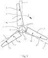
- the wind turbine has at least one rotor 1 with at least one rotor blade 2, vzw. with several, here with three rotor blades 2 on.
- the rotor blades 2 are operatively connected to a substantially horizontally disposed rotor shaft 3 via a rotor hub bearing.
- the rotor blades 2 are rotatable about a substantially radially aligned adjustment axis 4, wherein at least one adjusting device 5 acting on the adjustment axis 4 is provided for adjusting the rotor blades 2.
- the rotor 1 shown here of the wind turbine not shown in its entirety, here has three rotor blades 2.
- the wind turbine can have a plurality of rotor blades 2, for example four rotor blades or even only two, possibly even only one rotor blade 2.
- a rotational movement of the rotor shaft 3 is caused by the rotor blades 2 when it flows with the corresponding wind speed v wind , since the rotor blades 2 are effectively connected to the rotor shaft 3, which will be explained in more detail below.
- the rotor shaft 3 is arranged to extend substantially horizontally. This does not always have to be this way.
- the rotor shaft 3 is arranged slightly obliquely or even vertically. Vzw. However, the rotor shaft 3 is arranged to extend substantially horizontally and operatively connected to a generator, not shown here, to generate corresponding energy or electricity.
- the rotor blades 2 each have a stub shaft 6, which is rotatably mounted within a rotor hub 7.
- Fig. 1 is visible through the axis of the stub shaft 6 essentially defines the adjustment axis 4 or defined by the axis of the bearing 15, the adjustment axis 4.
- Out Fig.1 is also easy to see that the individual rotor blades 2, so the longitudinal axis of the rotor blades 2 do not coincide with the respective adjustment axis 4, but are arranged so that the respective pressure point D of the rotor blades 2 of the respective adjustment axis 4 lags behind during the rotation of the rotor 1 ,
- the rotational movement of the rotor 1 is in Fig. 1 represented by the corresponding arrow A.
- Fig. 2 now shows the rotor 1 in a schematic representation of the side. Good to see are in the rotor hub 7 via the stub shafts 6 mounted rotor blades 2 and the schematically indicated here and partially shown rotor shaft 3. Due to the representation in Fig. 2 It can be seen that the adjustment axes 4 with respect to the rotor shaft 3, although substantially radially, vzw. However, the adjustment axes 4 of the rotor blades 2 are inclined slightly to the front substantially, so that the rotor blades 2 form an acute angle ⁇ with the general rotor plane. The arrangement of the rotor blades 2, the formation of an angle ⁇ and the formation of a trailing pressure point D have an adjusting torque in the direction of feathering during operation of the wind turbine.
- the adjusting device 5 has at least one cam disc 9 cooperating with a control disc 8 and the cam disc 9 is arranged such that the axis of rotation of the cam disc 9 coincides with the adjustment axis 4.
- the adjusting device 5 now has at least one control disk 8 and at least one cam 9, which interact with each other substantially frictionally, the disadvantages mentioned are avoided to a considerable extent.
- no additional belt element must be provided and the signs of wear are now substantially reduced, since the adjusting device 5 thus formed is substantially not susceptible to wear.
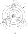
- FIGS Fig. 3 to 6 The preferred embodiment of the adjusting device 5 shown here, as shown in FIGS Fig. 3 to 6 can be seen, a control disk 8 and three cam 9.
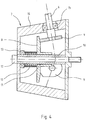
- Fig. 4 shows that the control disk 8 is arranged on an axis 10 within the rotor hub 7 and is axially displaceable thereon.
- the control disk 8 is rotatably mounted on the axle 10 by means of a bearing 11. It is from the Fig. 4 as well as from the Fig. 5 clearly recognize that the individual cams 9 are in frictional contact with the control disk 8.
- the control disk 8 is subjected to force by a spring element 12 in the direction of the cam disks 9.
- a spring element 12 in the direction of the cam disks 9.
- the spring element 12 is rotatably supported by means of a bearing 13, so that a rotation of the control disc 8 and also a corresponding rotation of the spring element 12 is made possible.
- the rotation axis of the control disk 8 corresponds to the axis of rotation of the rotor shaft 3.
- the adjusting device 5 consists essentially of a control disk 8 and three cams 9 and the bearing of the control disk 8 and the spring element 12 here.
- the number of cams 9 is substantially dependent on the number of rotor blades 2.
- the cams 9 are located respectively at the lower ends of the stub shafts 6 of the rotor blades 2 and are rotatably arranged here.
- the adjustment axes 4 of the respective rotor blades 2 are defined by the axes of the individual stub shafts 6.
- the respective stub shaft 6 is rotatably mounted within the peripheral wall 14 of the rotor hub 7.
- a corresponding bearing 15 is provided in each case.
- a corresponding number of shaft stumps 6 or cam disks 9 is now also provided. So it is quite conceivable that the adjusting device 5 therefore vzw. has two, four or more cams 9, which cooperate with the corresponding control disk 8. This is dependent on the respective embodiment of the wind power plant, in particular of the rotor 1.
- control disk 8 and the cam discs 9 may be different from the particular application and in particular depending on the forces occurring.
- steel and steel alloys but also corresponding other cast materials or corresponding mixtures as well as plastics in question. It is crucial that a punctual contact between the control disk 8 and the respective cam 9 is ensured. As a result, optimum storage of the control disk 8 and the cam 9 is possible.
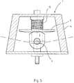
- the design of the spring element 12, here as a helical compression spring has been found to be a preferred embodiment. But it is also conceivable, other spring elements, for example. Disc springs or the like. Provide here.
- control disk 8 rotatable and the spring element 12 are rotatably mounted, which will be explained in more detail below.
- wear and tear, in particular abrasion between the control disk 8 and cam 9 are significantly minimized, because due to the possibility of rotation of the control disk 8 together with the helical compression spring, it comes to a low Reibverschl accompany and a high control quality of the adjustment device. 5
- control disk 8 and cam 9 are therefore preferred materials that ensure good contact between the elements, ie in particular materials that ensure a good rolling of the cam 9 on the control disk 8. It is particularly advantageous that the entire adjusting device 5 is arranged substantially within the rotor hub 7 and therefore the individual elements are protected from the weather here. As a result, the necessary occurring contacts are not due the penetration of water, or other weather influences, such as icing or dirt reduces or interferes with the interaction of the elements.
- the Fig. 5 and 6 show a cam 9 from the side in a schematic representation.
- the upper portion of the cam 9 has a corresponding contour 9a.
- the contour 9a of the cam 9 has two extremes 16. These extremes 16 are used for the realization of the "zero position" or the neutral position of the cam 9 on the control disk 8. In other words, with the help of the extrema 16, the zero position of the cam 9 relative to the control disk 8 is clearly defined. This ensures optimal adjustment of the neutral position of the rotor blades 2.
- the adjusting device 5 is disposed or integrated within the rotor hub 7.
- the axis 10, on which the control disk 8 is mounted, is hollow, so that the rotor hub 7 by means of a connecting element 17, vzw. by means of a screw with the rotor shaft 3 for transmitting the torque of the rotor 1 is connectable.
- the adjusting device 5 is constructed such that it can be integrated on the one hand inside the rotor hub 7, but on the other hand, the rotor hub 7 in a simple manner to the rotor shaft 3 by a connecting element 17, vzw. a screw element with the rotor shaft 3 can be screwed. This increases the ease of installation of the entire wind turbine, since only one connecting element is required for the assembly, which is additionally of great advantage. Adjustment device 5 and rotor hub 7 therefore form an easily assembled module.
- the adjusting device 5 thus serves as a control and / or regulating element for controlling / regulating the power P or rotational speed n of the wind power plant.
- the adjusting device 5 serves as a control and / or regulating element for controlling / regulating the power P or rotational speed n of the wind power plant.
- cam disks 9, control disk 8 and spring element 12 are now designed and arranged such that the holding torque or holding forces can be transmitted to the rotor blades 2 in a corresponding manner, so that their position can be controlled or regulated accordingly. This may again on the Fig. 1 to get expelled.
- the pressure point D of the rotor blades 2 of the respective adjustment axis 4 lags behind. As a result, it comes with flow at a wind speed v wind > v nominal , shown in Fig. 2 , to a rotation of the rotor blades 2 about the adjustment axis 4, in particular because the pressure point D lies just outside the respective adjustment axis 4.
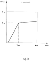
- Fig. 7 shows an increase in power Pnenn the wind turbine with increasing wind speed v wind to the value vnenn . Above the wind speed vnenn the wind turbine is therefore limited for safety reasons.
- Fig. 8 shows now that the adjustment device 5 is designed and / or formed such that the idle speed n rotor of the rotor 1 from a certain wind speed, here from the value v abr substantially only slightly increases, namely up to the wind speed v exr . Consequently, here the speed of the rotor is abmony from wind speed vr abr reasons of safety.
- the rotor blades 2 in the direction of the flag position also reduces the angle ⁇ .
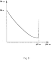
- Fig. 9 shows from the Abregeltician a steep drop in the holding torque M.
- the holding torque M decreases with increasing displacement angle phi until the end of Verstellwinkel Anlagens, where a steep increase takes place.
- This increase is realized by the contours 9a of the cams 9, namely by the "outer corner points", which are not specified.
- Fig. 9 Therefore, the "control characteristic" of the adjusting device 5 is therefore essentially defined by the formation / contour profile 9a of all cams and the spring element 12.
Description
Die Erfindung betrifft eine Windkraftanlage mit mindestens einem Rotor, wobei der Rotor mindestens ein Rotorblatt, vzw. mehrere Rotorblätter aufweist, wobei das Rotorblatt mit einer Rotorwelle wirksam verbunden ist, wobei das Rotorblatt um eine im wesentlichen radial ausgerichtete Verstellachse drehbar ist und wobei zur Einstellung des Rotorblattes mindestens eine Verstell-Einrichtung vorgesehen ist.The invention relates to a wind turbine with at least one rotor, wherein the rotor at least one rotor blade, vzw. a plurality of rotor blades, wherein the rotor blade is operatively connected to a rotor shaft, wherein the rotor blade is rotatable about a substantially radially aligned adjustment axis and wherein at least one adjusting device is provided for adjusting the rotor blade.
Im Stand der Technik, von dem die Erfindung ausgeht, ist eine Windkraftanlage bekannt (
Weiterhin ist im Stand der Technik eine Windkraftanlage bekannt (DE-PS
Schließlich ist aus
Die im Stand der Technik bekannten Windkraftanlagen, insbesondere deren Verstell-Einrichtungen zur Verstellung bzw. Positionierung der Rotorblätter sind noch nicht optimal ausgebildet. So ist bei der eingangs genannten Windkraftanlage (
Der Erfindung liegt daher die Aufgabe zugrunde, die eingangs genannte Windkraftanlage derart auszugestalten und weiterzubilden, dass zur Einstellung der Positionen der Rotorblätter das Spiel und die Toleranzkette der Kraftübertragungskette verringert ist, insbesondere auch der Montage- und Wartungsaufwand für eine derartige Verstell-Einrichtung und die damit verbundenen Kosten erheblich minimiert sind, wobei insbesondere die Einstellung / Positionierung aller Rotorblätter optimiert ist und vzw. die Verstell-Einrichtung vor Witterungseinflüssen gut schützbar ist.The invention is therefore based on the object, the above-mentioned wind turbine to design and further that for adjusting the positions of the rotor blades, the game and the tolerance chain of the power transmission chain is reduced, especially the installation and maintenance of such adjustment device and thus associated costs are significantly minimized, in particular, the setting / positioning of all rotor blades is optimized and vzw. the adjustment device is well protected from the weather.
Die zuvor aufgezeigte Aufgabe ist nun dadurch gelöst, dass die Verstell-Einrichtung mindestens eine mit einer Steuerscheibe zusammenwirkende Kurvenscheibe aufweist und die Kurvenscheibe derart angeordnet ist, dass die Drehachse der Kurvenscheibe mit der Verstellachse zusammenfällt. Dadurch, dass die Verstell-Einrichtung nunmehr so ausgebildet ist, dass sie einerseits eine Steuerscheibe, andererseits eine Kurvenscheibe aufweist, ist die Verstell-Einrichtung weniger verschleißanfällig. Insbesondere entfällt der im Stand der Technik bekannte und verwendete Riemen. Weiterhin ist die Verstell-Einrichtung so ausgebildet, dass diese für mehrere Rotorblätter gemeinsam verwendet werden kann, also durch eine einzige Verstell-Einrichtung, nämlich im wesentlichen mit einer Steuerscheibe, die auf vzw. mehrere Kurvenscheiben wirkt, alle Rotorblätter gemeinsam entsprechend verstellt werden können. Hierzu wirken die Steuerscheibe und die Kurvenscheibe entsprechend reibschlüssig zusammen, was im folgenden noch näher erläutert werden wird. Von Vorteil ist, dass die so ausgebildete Verstell-Einrichtung bevorzugt in einer Rotornabe vollständig integrierbar ist, und vzw. dort vollständig "einkapselbar" ist, so dass sie vor äußeren Witterungseinflüssen geschützt ist, was weitere Vorteile mit sich bringt. Hierdurch sind Elemente der Verstell-Einrichtung entsprechend vor den Witterungseinflüssen, insbesondere vor Korrosion, Vereisung etc. geschützt. Zusätzlich entfallen ebenfalls die im Stand der Technik verwendeten Stangenelemente des hier verwendeten Stangengetriebes. Da die Verstell-Einrichtung in eine Rotornabe integrierbar ist, weist diese daher aerodynamische Vorteile auf, was wiederum zu einer Leistungserhöhung der gesamten Windkraftanlage führt. Im Ergebnis sind die eingangs beschriebenen Nachteile vermieden und entscheidende Vorteile erzielt.The previously indicated object is now achieved in that the adjusting device has at least one cam disc cooperating with a control disk and the cam disk is arranged such that the axis of rotation of the cam disk coincides with the adjustment axis. The fact that the adjusting device is now designed so that on the one hand a control disk, on the other hand has a cam, the adjustment device is less susceptible to wear. In particular, the belt known and used in the prior art is eliminated. Furthermore, the adjusting device is designed so that it can be used for several rotor blades together, ie by a single adjustment device, namely essentially with a control disk, the vzw on. several cam disks acts, all rotor blades can be adjusted together accordingly. For this purpose, the control disk and the cam act correspondingly frictionally together, which will be explained in more detail below. It is advantageous that the thus formed adjusting device is preferably fully integrated in a rotor hub, and vzw. is completely "encapsulated" there, so that it is protected from external weather conditions, which brings with it further advantages. As a result, elements of the adjustment device are accordingly protected against the effects of the weather, in particular against corrosion, icing, etc. In addition, the rod elements of the rod transmission used in the prior art are also eliminated. Since the adjusting device can be integrated into a rotor hub, this therefore has aerodynamic advantages, which in turn leads to an increase in power of the entire wind turbine. As a result, the disadvantages described above are avoided and achieved decisive advantages.
Es gibt nun eine Vielzahl von Möglichkeiten die erfindungsgemäße Windkraftanlage in vorteilhafter Art und Weise auszugestalten und weiterzubilden. Hierfür darf zunächst auf die dem Patentanspruch 1 nachgeordneten Patentansprüche verwiesen werden. Im folgenden soll nun ein bevorzugtes Ausführungsbeispiel der Erfindung anhand der nachfolgenden Zeichnung und zugehörenden Beschreibung näher erläutert werden.There are now a variety of ways to design the wind turbine according to the invention in an advantageous manner and further. For this purpose, reference may first be made to the claims subordinate to claim 1. In the following, a preferred embodiment of the invention will now be explained in more detail with reference to the following drawings and associated description.
In der Zeichnung zeigt:
- Fig. 1
- den Rotor der erfindungsgemäßen Windkraftanlage von vorne in schematischer Darstellung,
- Fig. 2
- den Rotor der erfindungsgemäßen Windkraftanlage in schematischer Darstellung von der Seite,
- Fig. 3
- in schematischer Darstellung von vorne das Innere der Rotornabe, nämlich die wesentlichen Bestandteile der Verstell-Einrichtung mit Blick in die "geöffnete Rotornabe",
- Fig. 4
- die Rotornabe im Schnitt von der Seite in schematischer Darstellung mit der in der Rotornabe integrierten Verstell-Einrichtung,
- Fig. 5
- in schematischer Darstellung teilweise im Schnitt eine Draufsicht auf die Rotornabe mit integrierter Verstell-Einrichtung,
- Fig. 6
- in schematischer vergrößerter Darstellung von vorne eine einzelne Kurvenscheibe,
- Fig. 7
- in schematischer Darstellung eine Leistungskennlinie der erfindungsgemäßen Windkraftanlage in Abhängigkeit der Windgeschwindigkeit,
- Fig.8
- in schematischer Darstellung eine Leerlauf-Drehzahlkennlinie der erfindungsgemäßen Windkraftanlage in Abhängigkeit der Windgeschwindigkeit und
- Fig.9
- die Kennlinie des Haltemomentes für die Positionierung der Rotorblätter in schematischer Darstellung in Abhängigkeit des Verstellwinkels, also die "Reglercharakteristik" der Verstell-Einrichtung.
- Fig. 1
- the rotor of the wind turbine according to the invention from the front in a schematic representation,
- Fig. 2
- the rotor of the wind turbine according to the invention in a schematic representation of the side,
- Fig. 3
- in a schematic representation from the front, the interior of the rotor hub, namely the essential components of the adjustment device with a view into the "open rotor hub",
- Fig. 4
- the rotor hub in section from the side in a schematic representation with the integrated in the rotor hub adjustment device,
- Fig. 5
- in a schematic representation partially in section a plan view of the rotor hub with integrated adjustment device,
- Fig. 6
- in schematic enlarged representation from the front a single cam,
- Fig. 7
- a schematic representation of a performance curve of the wind turbine according to the invention as a function of wind speed,
- Figure 8
- a schematic representation of an idle speed characteristic of the wind turbine according to the invention in dependence on the wind speed and
- Figure 9
- the characteristic of the holding torque for the positioning of the rotor blades in a schematic representation as a function of the adjustment angle, ie the "controller characteristic" of the adjustment device.
Die
Der hier dargestellte Rotor 1 der in ihrer Gesamtheit nicht dargestellten Windkraftanlage weist hier drei Rotorblätter 2 auf. Es ist aber denkbar, dass die Windkraftanlage mehrere Rotorblätter 2 bspw. vier Rotorblätter oder auch nur zwei, womöglich auch sogar nur ein Rotorblatt 2 aufweisen kann. Hierbei wird durch die Rotorblätter 2 bei Anströmung mit der entsprechenden Windgeschwindigkeit vwind eine Rotationsbewegung der Rotorwelle 3 verursacht, da die Rotorblätter 2 mit der Rotorwelle 3 wirksam verbunden sind, was im folgenden noch näher erläutert werden soll. Die Rotorwelle 3 ist im wesentlichen horizontal verlaufend angeordnet. Dies muß nicht immer so sein. Es ist auch durchaus denkbar, dass die Rotorwelle 3 leicht schräg oder sogar vertikal angeordnet ist. Vzw. ist die Rotorwelle 3 jedoch im wesentlichen horizontal verlaufend angeordnet und mit einem hier nicht dargestellten Generator entsprechend wirksam verbunden, um entsprechende Energie bzw. Elektrizität zu erzeugen.The
Die Rotorblätter 2 weisen jeweils einen Wellenstumpf 6 auf, der innerhalb einer Rotornabe 7 drehbar gelagert ist. Wie
Die eingangs beschriebenen Nachteile sind nun dadurch vermieden, dass die Verstell-Einrichtung 5 mindestens eine mit einer Steuerscheibe 8 zusammenwirkende Kurvenscheibe 9 aufweist und die Kurvenscheibe 9 derart angeordnet ist, dass die Drehachse der Kurvenscheibe 9 mit der Verstellachse 4 zusammenfällt. Dadurch, dass die Verstell-Einrichtung 5 nunmehr mindestens eine Steuerscheibe 8 und mindestens eine Kurvenscheibe 9 aufweist, die im wesentlichen reibschlüssig miteinander zusammenwirken, sind die eingangs genannten Nachteile im erheblichen Maße vermieden. Einerseits muß kein zusätzliches Riemenelement mehr vorgesehen werden sowie die Verschleißerscheinungen nunmehr wesentlich verringert sind, da die so ausgebildete Verstell-Einrichtung 5 im wesentlichen eben nicht verschleißanfällig ist. Weiterhin müssen keine aufwendigen und verschleißanfälligen zusätzlichen Gelenke etc. vorgesehen werden, so dass eine kurze Kraftübertragungskette mit spielfreier Kraftübertragung, und daher geringe Toleranzen und ein exakter Blatteinstellwinkel der Rotorblätter 2 mit der so ausgebildeten Verstell-Einrichtung 5 realisierbar sind, was im folgenden noch ausführlich erläutert werden soll. Weiterhin sind hier die Steuer- bzw. Reglerelemente, welche die Verstell-Einrichtung 5 aufweist, vor Witterungseinflüssen wie Korrosion und Vereisung sehr gut geschützt, denn die Verstell-Einrichtung 5 kann innerhalb der Rotornabe 7 vollständig integriert werden, was im folgenden ebenfalls ausführlich beschrieben werden wird. Im Ergebnis ist eine kostengünstige, verschleißfreie sowie - im Endeffekt - nahezu keine Toleranzen aufweisende Verstell-Einrichtung 5 geschaffen, mit deren Hilfe die Rotorblätter 2 optimal positionierbar sind.The disadvantages described above are now avoided in that the adjusting device 5 has at least one
Die bevorzugte Ausführungsform der hier dargestellten Verstell-Einrichtung 5 weist, wie aus den
Die
Auch die Materialien aus denen die Steuerscheibe 8 und die Kurvenscheiben 9 hergestellt sind, können vom jeweiligen Anwendungsfall und insbesondere in Abhängigkeit der auftretenden Kräfte unterschiedlich sein. Es kommen hier Stahl sowie Stahllegierungen aber auch entsprechende andere Gussmaterialen bzw. entsprechende Mischungen wie auch Kunststoffe in Frage. Entscheidend ist, dass ein punktueller Kontakt zwischen der Steuerscheibe 8 und der jeweiligen Kurvenscheibe 9 gewährleistet ist. Im Ergebnis ist eine optimale Lagerung der Steuerscheibe 8 bzw. der Kurvenscheibe 9 ermöglicht.The materials from which the
Auch die Ausbildung des Federelementes 12, hier als Schraubendruckfeder hat sich als bevorzugte Ausführungsform herausgestellt. Es ist aber auch denkbar, andere Federelemente, bspw. Tellerfedern oder dgl. hier vorzusehen.The design of the
Ein wesentlicher Vorteil ist, dass die Steuerscheibe 8 rotierbar und auch das Federelement 12 rotierbar gelagert sind, was im folgenden noch näher erläutert werden soll. Hierdurch bedingt sind auch Verschleißerscheinungen, insbesondere Abrieb zwischen Steuerscheibe 8 und Kurvenscheiben 9 erheblich minimiert, denn aufgrund der Rotationsmöglichkeit der Steuerscheibe 8 zusammen mit der Schraubendruckfeder kommt es zu einem geringen Reibverschleiß und zu einer hohen Regelgüte der Verstell-Einrichtung 5.A significant advantage is that the
Als Materialien für Steuerscheibe 8 und Kurvenscheiben 9 kommen daher bevorzugt Materialien in Frage, die einen guten Kontakt zwischen den Elementen gewährleisten, also insbesondere Materialien, die ein gutes Abwälzen der Kurvenscheibe 9 auf der Steuerscheibe 8 gewährleisten. Hierbei ist insbesondere von Vorteil, dass die gesamte Verstell-Einrichtung 5 im wesentlichen innerhalb der Rotornabe 7 angeordnet ist und daher die einzelnen Elemente hier vor Witterungseinflüssen geschützt sind. Hierdurch bedingt werden die erforderlichen auftretenden Kontakte nicht durch das Eindringen von Wasser, oder anderen Witterungseinflüssen, wie Vereisungen oder Schmutz vermindert bzw. das Zusammenwirken der Elemente beeinträchtigt.As materials for
Die
Wie die
Mit Hilfe der Verstell-Einrichtung 5 ist nun eine Leistungs- und / oder Drehzahlsteuerung der Windkraftanlage ermöglicht. Dies soll im folgenden näher erläutert werden:
Die Verstell-Einrichtung 5 dient also als Steuer- und / oder Regelelement zur Steuerung / Regelung der Leistung P bzw. Drehzahl n der Windkraftanlage. Von besonderer Bedeutung ist hierbei die Ausbildung der Kurvenscheibe 9 bzw. der jeweiligen Kurvenscheiben 9, sowie des Federelementes 12, nämlich der hier vorgesehenen Federkraft des Federelementes 12 sowie der Ausbildung der Kurvenkontur 9a der Kurvenscheibe 9.With the help of the adjusting device 5 is now a power and / or speed control of the wind turbine allows. This will be explained in more detail below:
The adjusting device 5 thus serves as a control and / or regulating element for controlling / regulating the power P or rotational speed n of the wind power plant. Of particular importance here is the formation of the
Alle diese Elemente, also Kurvenscheiben 9, Steuerscheibe 8 und Federelement 12 sind nun derart ausgebildet und angeordnet, dass das Haltemoment bzw. die Haltekräfte entsprechend auf die Rotorblätter 2 übertragbar sind, so dass deren Position entsprechend steuerbar bzw. regelbar ist. Hierzu darf nochmals auf die
Die Verstell-Einrichtung 5 ist nun derart ausgebildet, dass ab einer bestimmten Windgeschwindigkeit vnenn die Leistung Pnenn der Windkraftanlage im wesentlichen konstant bleibt, so wie dies in der
Aus der
Im Ergebnis sind für eine Windkraftanlage mit einer derart ausgebildeten Verstell-Einrichtung 5 entscheidende Vorteile erzielt, wobei der Arbeits-, Montage- und Wartungsaufwand verringert sind, die Verschleißerscheinungen vermindert sind, ein gutes Reglerverhalten der Verstell-Einrichtung 5 erzielbar ist und sämtliche Vorteile bei nur geringen Kosten realisierbar sind.As a result, 5 key advantages are achieved for a wind turbine with such a trained adjustment device, the work, installation and maintenance costs are reduced, the signs of wear are reduced, a good controller behavior of the adjustment device 5 can be achieved and all the benefits in only low costs are feasible.
- 11
- Rotorrotor
- 22
- Rotorblattrotor blade
- 33
- Rotorwellerotor shaft
- 44
- Verstellachseadjustment axis
- 55
- Verstell-EinrichtungAdjustment device
- 66
- Wellenstumpfstub shaft
- 77
- Rotornaberotor hub
- 88th
- Steuerscheibecontrol disc
- 99
- Kurvenscheibecam
- 9a9a
- Konturcontour
- 1010
- Achseaxis
- 1111
- Lagercamp
- 1212
- Federelementspring element
- 1313
- Lagercamp
- 1414
- Umfangswandungperipheral
- 1515
- Lagercamp
- 1616
- ExtremaExtrema
- 1717
- Schraubelementscrew
- WW
- Windwind
- DD
- Druckpunktpressure point
- Ms M s
- MassenschwerpunktCenter of gravity
- AA
- Pfeilarrow
- PP
- Leistungpower
- nn
- Drehzahlrotation speed
- MM
- Haltemomentholding torque
- phiphi
- Verstellwinkeldisplacement
- vwind v wind
- Windgeschwindigkeitwind speed
- γγ
- Konuswinkelcone angle
Claims (20)
- Wind energy installation having at least one rotor (1) with the rotor (1) having at least one rotor blade (2), preferably two or more rotor blades (2), wherein the rotor blade (2) is effectively connected to a rotor shaft (3), wherein the rotor blade (2) can rotate about an essentially radially aligned pitch control axis (4), and wherein at least one pitch control device (5) is provided in order to adjust the rotor blade (2), characterized in that the pitch control device (5) has at least one cam disk (9) which interacts with a control disk (8), and the cam disk (9) is arranged such that the rotation axis of the cam disk (9) coincides with the pitch control axis (4).
- Wind energy installation according to Claim 1, characterized in that the control disk (8) is arranged and can be moved axially on a shaft (10) within the rotor hub (7).
- Wind energy installation according to Claim 2, characterized in that the control disk (8) is mounted on the shaft (10) by means of a bearing (11) such that it can rotate.
- Wind energy installation according to one of Claims 1 to 3, characterized in that the control disk (8) makes friction contact with the cam disk (9).
- Wind energy installation according to one of Claims 1 to 4, characterized in that the control disk (8) has force applied to it by at least one spring element (12) in the direction of the cam disk (9).
- Wind energy installation according to Claim 5, characterized in that the spring element (12) is mounted such that it can rotate, such that rotation of the control disk (8) and of the spring element (12) is possible.
- Wind energy installation according to one of Claims 1 to 6, characterized in that the rotation axis of the control disk (8) corresponds to the rotation axis of the rotor shaft (3).
- Wind energy installation according to one of Claims 1 to 7, characterized in that the cam disk (9) is arranged at the lower end of a shaft stub (6) of the rotor blade (2) such that they rotate together, and the pitch control axis (4) of the rotor blade (2) is defined by the axis of the shaft stub (6).
- Wind energy installation according to Claim 8, characterized in that the shaft stub (6) is mounted within the circumferential wall (14) of the rotor hub (7) such that it can rotate.
- Wind energy installation according to one of Claims 1 to 9, characterized in that the contour profile (9a) of the cam disk (9) has two extremes (16) for provision of the null position or the neutral position of the cam disk (9) on the control disk (8).
- Wind energy installation according to Claim 8 or according to Claims 8 and 10, characterized in that the three rotor blades (2) are provided, and the shaft stubs (6) of the rotor blades (2) are mounted within the circumferential wall (14) of the rotor hub (7) such that they can rotate.
- Wind energy installation according to one of Claims 2 to 11, characterized in that the pitch control device (5) is arranged within the rotor hub (7).
- Wind energy installation according to one of Claims 2 to 12, characterized in that the shaft (10) of the control disk (8) is hollow, so that the rotor hub (7) can be connected by means of a connecting element (17) to the rotor shaft (3) in order to transmit a torque.
- Wind energy installation according to one of Claims 1 to 13, characterized in that the rotor blades (2) are arranged such that the respective pressure point (D) on each of the rotor blades (2) runs behind the respective pitch control axis (4).
- Wind energy installation according to one of Claims 1 to 14, characterized in that the pitch control axes (4) of the rotor blades (2) are slightly inclined, so that the rotor blades (2) form an acute angle (γ) with the general rotor plane.
- Wind energy installation according to one of Claims 1 to 15, characterized in that the pitch control device (5) allows a power and/or rotation speed of the wind energy installation to be controlled.
- Wind energy installation according to one of Claims 5 to 16, characterized in that cam disks (9), the control disk (8) and the spring element (12) are designed and arranged such that holding torques (M) or holding forces can be transmitted to the rotor blades (2), so that their positioning can be controlled.
- Wind energy installation according to one of Claims 5 to 17, characterized in that the cam disks (9), the control disk (8) and the spring element (12) are designed and arranged such that the pitch control angle range of the rotor blades (2) is determined by a specific characteristic of the holding torque (M).
- Wind energy installation according to one of Claims 1 to 18, characterized in that the pitch control device (5) is designed and/or configured such that the rated power (Pnenn) of the wind energy installation remains constant above a specific wind speed (vnenn), namely the wind energy installation is regulated above said specific wind speed (vnenn).
- Wind energy installation according to one of Claims 1 to 19, characterized in that the pitch control device (5) is designed and/or configured such that the idling rotation speed (n) of the rotor (1) is regulated above a specific wind speed (vabr).
Applications Claiming Priority (3)
| Application Number | Priority Date | Filing Date | Title |
|---|---|---|---|
| DE10226713A DE10226713B4 (en) | 2002-06-14 | 2002-06-14 | Wind turbine |
| DE10226713 | 2002-06-14 | ||
| PCT/DE2003/001868 WO2003106839A1 (en) | 2002-06-14 | 2003-06-05 | Wind power plant |
Publications (2)
| Publication Number | Publication Date |
|---|---|
| EP1516121A1 EP1516121A1 (en) | 2005-03-23 |
| EP1516121B1 true EP1516121B1 (en) | 2018-09-12 |
Family
ID=29719109
Family Applications (1)
| Application Number | Title | Priority Date | Filing Date |
|---|---|---|---|
| EP03759829.9A Expired - Lifetime EP1516121B1 (en) | 2002-06-14 | 2003-06-05 | Wind power plant |
Country Status (5)
| Country | Link |
|---|---|
| US (1) | US7137785B2 (en) |
| EP (1) | EP1516121B1 (en) |
| AU (1) | AU2003250744A1 (en) |
| DE (1) | DE10226713B4 (en) |
| WO (1) | WO2003106839A1 (en) |
Families Citing this family (18)
| Publication number | Priority date | Publication date | Assignee | Title |
|---|---|---|---|---|
| DE102005014026A1 (en) * | 2005-03-23 | 2006-09-28 | Rudolf Eckart | Rotor arrangement for wind energy unit comprises rotor blade shaft on which an adjustable rotor blade is mounted and has bearing linked to hub to which rim is fixed via spokes |
| ZA200800898B (en) * | 2005-07-15 | 2009-04-29 | Oceanlinx Ltd | A blade pitch control mechanism |
| GB0609799D0 (en) * | 2006-05-18 | 2006-06-28 | Euro Projects Ltd | A turbine blade support assembly |
| WO2009150713A1 (en) * | 2008-06-10 | 2009-12-17 | 三菱重工業株式会社 | Blade pitch angle control device and wind turbine generator |
| CN101981311B (en) * | 2009-04-10 | 2013-07-17 | 三菱重工业株式会社 | Pitch drive of wind power generator and wind power generator |
| US8770934B2 (en) * | 2009-12-16 | 2014-07-08 | Hamilton Sundstrand Corporation | Teeter mechanism for a multiple-bladed wind turbine |
| US8622697B2 (en) | 2010-11-18 | 2014-01-07 | Hamilton Sundstrand Corporation | Ram air turbine bearing spacer |
| US9726149B2 (en) | 2011-01-18 | 2017-08-08 | Hamilton Sundstrand Corporation | Spiral bevel gear set for ram air turbine |
| EP2546517B1 (en) * | 2011-07-13 | 2016-03-30 | ALSTOM Renewable Technologies | Wind turbine rotor |
| DE102012013365A1 (en) * | 2012-06-22 | 2013-12-24 | Richard Strehler | Central pitch adjustment for wind turbines, has two component assemblies, where former component assembly is in circumferential rotating hub and latter component assembly is in fixed installation part |
| CN103470712B (en) * | 2013-09-23 | 2016-01-20 | 西北农林科技大学 | A kind of speed self balancing device |
| CN104295449B (en) * | 2014-09-23 | 2015-07-15 | 丁健威 | Wind power generation device with rear-mounted blades |
| DE102016111954A1 (en) * | 2016-06-30 | 2018-01-04 | Wobben Properties Gmbh | Pitch system of a wind turbine and wind turbine |
| DE102016014339B4 (en) | 2016-12-02 | 2021-05-27 | Martin van Egeren | Wind turbine |
| US10975840B2 (en) | 2016-12-02 | 2021-04-13 | Klaus Krieger | Wind power plant |
| DE202016007375U1 (en) | 2016-12-02 | 2017-01-23 | Martin van Egeren | Wind turbine |
| DE102017104474A1 (en) | 2017-03-03 | 2018-09-06 | Wobben Properties Gmbh | Adjustment unit for an azimuth adjustment and / or for a pitch adjustment of a wind energy plant and method |
| DE102017004909A1 (en) * | 2017-05-18 | 2018-11-22 | Enbreeze Gmbh | Device for adjusting the rotor blades of a flow force plant |
Family Cites Families (13)
| Publication number | Priority date | Publication date | Assignee | Title |
|---|---|---|---|---|
| FR1433734A (en) * | 1965-04-26 | 1966-04-01 | Wind motor | |
| US3469633A (en) * | 1967-10-19 | 1969-09-30 | Gen Dynamics Corp | Control means for air driven turbines |
| US4124330A (en) * | 1974-10-09 | 1978-11-07 | United Technologies Corporation | Cam-operated pitch-change apparatus |
| IT1091536B (en) * | 1977-12-23 | 1985-07-06 | Fiat Spa | DEVICE FOR THE ADJUSTMENT OF THE PITCH OF THE BLADES OF A WIND MOTOR |
| DE2930062B1 (en) * | 1979-07-25 | 1980-02-14 | Maschf Augsburg Nuernberg Ag | Wind turbine with a one or two-bladed rotor arranged on a tower |
| US4495423A (en) * | 1981-09-10 | 1985-01-22 | Felt Products Mfg. Co. | Wind energy conversion system |
| US4435646A (en) * | 1982-02-24 | 1984-03-06 | North Wind Power Company, Inc. | Wind turbine rotor control system |
| US4743163A (en) * | 1985-11-22 | 1988-05-10 | Sundstrand Corporation | Ram air turbine control system |
| DE3628626A1 (en) * | 1986-08-22 | 1988-02-25 | Peter Dipl Ing Frieden | Propeller windmill with expanded field of application |
| GB2233400A (en) * | 1989-06-20 | 1991-01-09 | George William James Bell | Automatic variable pitch propellor |
| DE4241631C2 (en) * | 1992-12-10 | 1994-11-24 | Peter Dipl Ing Frieden | Wind turbine |
| US6158953A (en) * | 1998-12-04 | 2000-12-12 | Lamont; John S | Wind turbine with variable position blades |
| DE19941630C1 (en) * | 1999-09-01 | 2001-03-08 | Pvo Engineering Ltd | Wind-powered energy plant has coupling belt passed around belt discs associated with blade angle adjustment drives for each rotor blade |
-
2002
- 2002-06-14 DE DE10226713A patent/DE10226713B4/en not_active Expired - Fee Related
-
2003
- 2003-06-05 AU AU2003250744A patent/AU2003250744A1/en not_active Abandoned
- 2003-06-05 EP EP03759829.9A patent/EP1516121B1/en not_active Expired - Lifetime
- 2003-06-05 WO PCT/DE2003/001868 patent/WO2003106839A1/en not_active Application Discontinuation
-
2004
- 2004-12-14 US US11/011,387 patent/US7137785B2/en not_active Expired - Lifetime
Non-Patent Citations (1)
| Title |
|---|
| None * |
Also Published As
| Publication number | Publication date |
|---|---|
| AU2003250744A1 (en) | 2003-12-31 |
| EP1516121A1 (en) | 2005-03-23 |
| DE10226713B4 (en) | 2004-07-08 |
| WO2003106839A1 (en) | 2003-12-24 |
| US20050118026A1 (en) | 2005-06-02 |
| DE10226713A1 (en) | 2004-01-08 |
| US7137785B2 (en) | 2006-11-21 |
Similar Documents
| Publication | Publication Date | Title |
|---|---|---|
| EP1516121B1 (en) | Wind power plant | |
| EP1816346B1 (en) | Blade pitch adjustment device for a wind turbine blade | |
| DE112008000344B4 (en) | Power transmission device and manufacturing method therefor | |
| EP1266137B1 (en) | Bearing for an adjustable rotor blade on a wind energy plant | |
| EP1440240B1 (en) | Generator for a hydro-electric station | |
| DE2632697A1 (en) | WIND POWER MACHINE | |
| EP1002949A2 (en) | Vertical axis wind turbine | |
| DE10003385A1 (en) | Wind turbine | |
| DE3227700A1 (en) | WIND ENERGY CONVERTER | |
| WO2003093695A1 (en) | Hydrodynamic brake | |
| EP2885533A1 (en) | Fluid flow power plant | |
| DE3628626C2 (en) | ||
| DE3117996C2 (en) | ||
| DE102015104316A1 (en) | Wave gear for an actuator of a steering system | |
| DE10251388B4 (en) | Rotor of a wind turbine | |
| DE202012000907U1 (en) | Flow turbine | |
| DE202016007375U1 (en) | Wind turbine | |
| EP3548736B1 (en) | Wind power plant | |
| DE2948112A1 (en) | Automatic controller for limiting speed of windmill - has self-adjusting vanes controlled by levers and centrifugal weights | |
| EP4103835B1 (en) | Rotor comprising rotor blades | |
| DE102013211683B4 (en) | Wind power plant | |
| DE212016000270U1 (en) | Wind power station | |
| DE202010003488U1 (en) | Device for converting wind energy into mechanical energy | |
| DE102011104250B4 (en) | water wheel | |
| DE102016014339A1 (en) | Wind turbine |
Legal Events
| Date | Code | Title | Description |
|---|---|---|---|
| PUAI | Public reference made under article 153(3) epc to a published international application that has entered the european phase |
Free format text: ORIGINAL CODE: 0009012 |
|
| 17P | Request for examination filed |
Effective date: 20041216 |
|
| AK | Designated contracting states |
Kind code of ref document: A1 Designated state(s): AT BE BG CH CY CZ DE DK EE ES FI FR GB GR HU IE IT LI LU MC NL PT RO SE SI SK TR |
|
| AX | Request for extension of the european patent |
Extension state: AL LT LV MK |
|
| DAX | Request for extension of the european patent (deleted) | ||
| 17Q | First examination report despatched |
Effective date: 20100112 |
|
| STAA | Information on the status of an ep patent application or granted ep patent |
Free format text: STATUS: EXAMINATION IS IN PROGRESS |
|
| REG | Reference to a national code |
Ref country code: DE Ref legal event code: R079 Ref document number: 50315781 Country of ref document: DE Free format text: PREVIOUS MAIN CLASS: F03D0007020000 Ipc: F03D0007040000 |
|
| GRAP | Despatch of communication of intention to grant a patent |
Free format text: ORIGINAL CODE: EPIDOSNIGR1 |
|
| STAA | Information on the status of an ep patent application or granted ep patent |
Free format text: STATUS: GRANT OF PATENT IS INTENDED |
|
| RIC1 | Information provided on ipc code assigned before grant |
Ipc: F03D 7/04 20060101AFI20180115BHEP Ipc: F03D 7/02 20060101ALI20180115BHEP |
|
| INTG | Intention to grant announced |
Effective date: 20180215 |
|
| GRAS | Grant fee paid |
Free format text: ORIGINAL CODE: EPIDOSNIGR3 |
|
| GRAA | (expected) grant |
Free format text: ORIGINAL CODE: 0009210 |
|
| STAA | Information on the status of an ep patent application or granted ep patent |
Free format text: STATUS: THE PATENT HAS BEEN GRANTED |
|
| AK | Designated contracting states |
Kind code of ref document: B1 Designated state(s): AT BE BG CH CY CZ DE DK EE ES FI FR GB GR HU IE IT LI LU MC NL PT RO SE SI SK TR |
|
| REG | Reference to a national code |
Ref country code: GB Ref legal event code: FG4D Free format text: NOT ENGLISH |
|
| REG | Reference to a national code |
Ref country code: CH Ref legal event code: EP |
|
| REG | Reference to a national code |
Ref country code: IE Ref legal event code: FG4D Free format text: LANGUAGE OF EP DOCUMENT: GERMAN |
|
| REG | Reference to a national code |
Ref country code: DE Ref legal event code: R096 Ref document number: 50315781 Country of ref document: DE |
|
| REG | Reference to a national code |
Ref country code: AT Ref legal event code: REF Ref document number: 1040902 Country of ref document: AT Kind code of ref document: T Effective date: 20181015 |
|
| REG | Reference to a national code |
Ref country code: NL Ref legal event code: MP Effective date: 20180912 |
|
| REG | Reference to a national code |
Ref country code: DE Ref legal event code: R082 Ref document number: 50315781 Country of ref document: DE Representative=s name: HUEBSCH, KIRSCHNER & PARTNER, PATENTANWAELTE U, DE |
|
| PG25 | Lapsed in a contracting state [announced via postgrant information from national office to epo] |
Ref country code: GR Free format text: LAPSE BECAUSE OF FAILURE TO SUBMIT A TRANSLATION OF THE DESCRIPTION OR TO PAY THE FEE WITHIN THE PRESCRIBED TIME-LIMIT Effective date: 20181213 Ref country code: BG Free format text: LAPSE BECAUSE OF FAILURE TO SUBMIT A TRANSLATION OF THE DESCRIPTION OR TO PAY THE FEE WITHIN THE PRESCRIBED TIME-LIMIT Effective date: 20181212 Ref country code: FI Free format text: LAPSE BECAUSE OF FAILURE TO SUBMIT A TRANSLATION OF THE DESCRIPTION OR TO PAY THE FEE WITHIN THE PRESCRIBED TIME-LIMIT Effective date: 20180912 Ref country code: SE Free format text: LAPSE BECAUSE OF FAILURE TO SUBMIT A TRANSLATION OF THE DESCRIPTION OR TO PAY THE FEE WITHIN THE PRESCRIBED TIME-LIMIT Effective date: 20180912 |
|
| REG | Reference to a national code |
Ref country code: CH Ref legal event code: PK Free format text: BERICHTIGUNGEN |
|
| RIC2 | Information provided on ipc code assigned after grant |
Ipc: F03D 7/02 20060101ALI20180115BHEP Ipc: F03D 7/04 20060101AFI20180115BHEP |
|
| PG25 | Lapsed in a contracting state [announced via postgrant information from national office to epo] |
Ref country code: ES Free format text: LAPSE BECAUSE OF FAILURE TO SUBMIT A TRANSLATION OF THE DESCRIPTION OR TO PAY THE FEE WITHIN THE PRESCRIBED TIME-LIMIT Effective date: 20180912 |
|
| PG25 | Lapsed in a contracting state [announced via postgrant information from national office to epo] |
Ref country code: IT Free format text: LAPSE BECAUSE OF FAILURE TO SUBMIT A TRANSLATION OF THE DESCRIPTION OR TO PAY THE FEE WITHIN THE PRESCRIBED TIME-LIMIT Effective date: 20180912 Ref country code: RO Free format text: LAPSE BECAUSE OF FAILURE TO SUBMIT A TRANSLATION OF THE DESCRIPTION OR TO PAY THE FEE WITHIN THE PRESCRIBED TIME-LIMIT Effective date: 20180912 Ref country code: EE Free format text: LAPSE BECAUSE OF FAILURE TO SUBMIT A TRANSLATION OF THE DESCRIPTION OR TO PAY THE FEE WITHIN THE PRESCRIBED TIME-LIMIT Effective date: 20180912 Ref country code: CZ Free format text: LAPSE BECAUSE OF FAILURE TO SUBMIT A TRANSLATION OF THE DESCRIPTION OR TO PAY THE FEE WITHIN THE PRESCRIBED TIME-LIMIT Effective date: 20180912 Ref country code: NL Free format text: LAPSE BECAUSE OF FAILURE TO SUBMIT A TRANSLATION OF THE DESCRIPTION OR TO PAY THE FEE WITHIN THE PRESCRIBED TIME-LIMIT Effective date: 20180912 |
|
| PG25 | Lapsed in a contracting state [announced via postgrant information from national office to epo] |
Ref country code: PT Free format text: LAPSE BECAUSE OF FAILURE TO SUBMIT A TRANSLATION OF THE DESCRIPTION OR TO PAY THE FEE WITHIN THE PRESCRIBED TIME-LIMIT Effective date: 20190112 Ref country code: SK Free format text: LAPSE BECAUSE OF FAILURE TO SUBMIT A TRANSLATION OF THE DESCRIPTION OR TO PAY THE FEE WITHIN THE PRESCRIBED TIME-LIMIT Effective date: 20180912 |
|
| REG | Reference to a national code |
Ref country code: DE Ref legal event code: R097 Ref document number: 50315781 Country of ref document: DE |
|
| PLBE | No opposition filed within time limit |
Free format text: ORIGINAL CODE: 0009261 |
|
| STAA | Information on the status of an ep patent application or granted ep patent |
Free format text: STATUS: NO OPPOSITION FILED WITHIN TIME LIMIT |
|
| PG25 | Lapsed in a contracting state [announced via postgrant information from national office to epo] |
Ref country code: DK Free format text: LAPSE BECAUSE OF FAILURE TO SUBMIT A TRANSLATION OF THE DESCRIPTION OR TO PAY THE FEE WITHIN THE PRESCRIBED TIME-LIMIT Effective date: 20180912 |
|
| 26N | No opposition filed |
Effective date: 20190613 |
|
| PG25 | Lapsed in a contracting state [announced via postgrant information from national office to epo] |
Ref country code: SI Free format text: LAPSE BECAUSE OF FAILURE TO SUBMIT A TRANSLATION OF THE DESCRIPTION OR TO PAY THE FEE WITHIN THE PRESCRIBED TIME-LIMIT Effective date: 20180912 |
|
| PG25 | Lapsed in a contracting state [announced via postgrant information from national office to epo] |
Ref country code: MC Free format text: LAPSE BECAUSE OF FAILURE TO SUBMIT A TRANSLATION OF THE DESCRIPTION OR TO PAY THE FEE WITHIN THE PRESCRIBED TIME-LIMIT Effective date: 20180912 |
|
| REG | Reference to a national code |
Ref country code: CH Ref legal event code: PL |
|
| REG | Reference to a national code |
Ref country code: BE Ref legal event code: MM Effective date: 20190630 |
|
| PG25 | Lapsed in a contracting state [announced via postgrant information from national office to epo] |
Ref country code: TR Free format text: LAPSE BECAUSE OF FAILURE TO SUBMIT A TRANSLATION OF THE DESCRIPTION OR TO PAY THE FEE WITHIN THE PRESCRIBED TIME-LIMIT Effective date: 20180912 |
|
| PG25 | Lapsed in a contracting state [announced via postgrant information from national office to epo] |
Ref country code: IE Free format text: LAPSE BECAUSE OF NON-PAYMENT OF DUE FEES Effective date: 20190605 |
|
| PG25 | Lapsed in a contracting state [announced via postgrant information from national office to epo] |
Ref country code: LI Free format text: LAPSE BECAUSE OF NON-PAYMENT OF DUE FEES Effective date: 20190630 Ref country code: LU Free format text: LAPSE BECAUSE OF NON-PAYMENT OF DUE FEES Effective date: 20190605 Ref country code: BE Free format text: LAPSE BECAUSE OF NON-PAYMENT OF DUE FEES Effective date: 20190630 Ref country code: CH Free format text: LAPSE BECAUSE OF NON-PAYMENT OF DUE FEES Effective date: 20190630 |
|
| REG | Reference to a national code |
Ref country code: AT Ref legal event code: MM01 Ref document number: 1040902 Country of ref document: AT Kind code of ref document: T Effective date: 20190605 |
|
| PG25 | Lapsed in a contracting state [announced via postgrant information from national office to epo] |
Ref country code: AT Free format text: LAPSE BECAUSE OF NON-PAYMENT OF DUE FEES Effective date: 20190605 |
|
| PG25 | Lapsed in a contracting state [announced via postgrant information from national office to epo] |
Ref country code: CY Free format text: LAPSE BECAUSE OF FAILURE TO SUBMIT A TRANSLATION OF THE DESCRIPTION OR TO PAY THE FEE WITHIN THE PRESCRIBED TIME-LIMIT Effective date: 20180912 |
|
| PG25 | Lapsed in a contracting state [announced via postgrant information from national office to epo] |
Ref country code: HU Free format text: LAPSE BECAUSE OF FAILURE TO SUBMIT A TRANSLATION OF THE DESCRIPTION OR TO PAY THE FEE WITHIN THE PRESCRIBED TIME-LIMIT; INVALID AB INITIO Effective date: 20030605 |
|
| PGFP | Annual fee paid to national office [announced via postgrant information from national office to epo] |
Ref country code: FR Payment date: 20210621 Year of fee payment: 19 |
|
| PGFP | Annual fee paid to national office [announced via postgrant information from national office to epo] |
Ref country code: GB Payment date: 20210623 Year of fee payment: 19 |
|
| PGFP | Annual fee paid to national office [announced via postgrant information from national office to epo] |
Ref country code: DE Payment date: 20210714 Year of fee payment: 19 |
|
| REG | Reference to a national code |
Ref country code: DE Ref legal event code: R119 Ref document number: 50315781 Country of ref document: DE |
|
| GBPC | Gb: european patent ceased through non-payment of renewal fee |
Effective date: 20220605 |
|
| PG25 | Lapsed in a contracting state [announced via postgrant information from national office to epo] |
Ref country code: FR Free format text: LAPSE BECAUSE OF NON-PAYMENT OF DUE FEES Effective date: 20220630 |
|
| PG25 | Lapsed in a contracting state [announced via postgrant information from national office to epo] |
Ref country code: GB Free format text: LAPSE BECAUSE OF NON-PAYMENT OF DUE FEES Effective date: 20220605 Ref country code: DE Free format text: LAPSE BECAUSE OF NON-PAYMENT OF DUE FEES Effective date: 20230103 |