EP1516121B1 - Installation d'energie eolienne - Google Patents
Installation d'energie eolienne Download PDFInfo
- Publication number
- EP1516121B1 EP1516121B1 EP03759829.9A EP03759829A EP1516121B1 EP 1516121 B1 EP1516121 B1 EP 1516121B1 EP 03759829 A EP03759829 A EP 03759829A EP 1516121 B1 EP1516121 B1 EP 1516121B1
- Authority
- EP
- European Patent Office
- Prior art keywords
- rotor
- wind energy
- energy installation
- installation according
- disk
- Prior art date
- Legal status (The legal status is an assumption and is not a legal conclusion. Google has not performed a legal analysis and makes no representation as to the accuracy of the status listed.)
- Expired - Lifetime
Links
Images


Classifications
-
- F—MECHANICAL ENGINEERING; LIGHTING; HEATING; WEAPONS; BLASTING
- F03—MACHINES OR ENGINES FOR LIQUIDS; WIND, SPRING, OR WEIGHT MOTORS; PRODUCING MECHANICAL POWER OR A REACTIVE PROPULSIVE THRUST, NOT OTHERWISE PROVIDED FOR
- F03D—WIND MOTORS
- F03D7/00—Controlling wind motors
- F03D7/02—Controlling wind motors the wind motors having rotation axis substantially parallel to the air flow entering the rotor
- F03D7/04—Automatic control; Regulation
- F03D7/041—Automatic control; Regulation by means of a mechanical governor
-
- F—MECHANICAL ENGINEERING; LIGHTING; HEATING; WEAPONS; BLASTING
- F03—MACHINES OR ENGINES FOR LIQUIDS; WIND, SPRING, OR WEIGHT MOTORS; PRODUCING MECHANICAL POWER OR A REACTIVE PROPULSIVE THRUST, NOT OTHERWISE PROVIDED FOR
- F03D—WIND MOTORS
- F03D7/00—Controlling wind motors
- F03D7/02—Controlling wind motors the wind motors having rotation axis substantially parallel to the air flow entering the rotor
- F03D7/022—Adjusting aerodynamic properties of the blades
- F03D7/0224—Adjusting blade pitch
-
- F—MECHANICAL ENGINEERING; LIGHTING; HEATING; WEAPONS; BLASTING
- F05—INDEXING SCHEMES RELATING TO ENGINES OR PUMPS IN VARIOUS SUBCLASSES OF CLASSES F01-F04
- F05B—INDEXING SCHEME RELATING TO WIND, SPRING, WEIGHT, INERTIA OR LIKE MOTORS, TO MACHINES OR ENGINES FOR LIQUIDS COVERED BY SUBCLASSES F03B, F03D AND F03G
- F05B2260/00—Function
- F05B2260/70—Adjusting of angle of incidence or attack of rotating blades
- F05B2260/75—Adjusting of angle of incidence or attack of rotating blades the adjusting mechanism not using auxiliary power sources, e.g. servos
-
- F—MECHANICAL ENGINEERING; LIGHTING; HEATING; WEAPONS; BLASTING
- F05—INDEXING SCHEMES RELATING TO ENGINES OR PUMPS IN VARIOUS SUBCLASSES OF CLASSES F01-F04
- F05B—INDEXING SCHEME RELATING TO WIND, SPRING, WEIGHT, INERTIA OR LIKE MOTORS, TO MACHINES OR ENGINES FOR LIQUIDS COVERED BY SUBCLASSES F03B, F03D AND F03G
- F05B2260/00—Function
- F05B2260/70—Adjusting of angle of incidence or attack of rotating blades
- F05B2260/77—Adjusting of angle of incidence or attack of rotating blades the adjusting mechanism driven or triggered by centrifugal forces
-
- Y—GENERAL TAGGING OF NEW TECHNOLOGICAL DEVELOPMENTS; GENERAL TAGGING OF CROSS-SECTIONAL TECHNOLOGIES SPANNING OVER SEVERAL SECTIONS OF THE IPC; TECHNICAL SUBJECTS COVERED BY FORMER USPC CROSS-REFERENCE ART COLLECTIONS [XRACs] AND DIGESTS
- Y02—TECHNOLOGIES OR APPLICATIONS FOR MITIGATION OR ADAPTATION AGAINST CLIMATE CHANGE
- Y02E—REDUCTION OF GREENHOUSE GAS [GHG] EMISSIONS, RELATED TO ENERGY GENERATION, TRANSMISSION OR DISTRIBUTION
- Y02E10/00—Energy generation through renewable energy sources
- Y02E10/70—Wind energy
- Y02E10/72—Wind turbines with rotation axis in wind direction
Definitions
- the invention relates to a wind turbine with at least one rotor, wherein the rotor at least one rotor blade, vzw. a plurality of rotor blades, wherein the rotor blade is operatively connected to a rotor shaft, wherein the rotor blade is rotatable about a substantially radially aligned adjustment axis and wherein at least one adjusting device is provided for adjusting the rotor blade.
- a wind turbine is known ( DE 42 41 631 C2 ), wherein the rotor has three rotor blades and wherein the rotor blades are operatively connected via rotatably mounted stub shafts via a rotor blade bearing with the rotor shaft. Due to the fact that the rotor blades are rotatably mounted, they are - with respect to the axis of the rotor shaft - rotatable about a substantially radially aligned adjustment axis. For adjustment, that is to say for positioning the respective rotor blade, an adjustment device acting on the adjustment axis is provided in each case.
- the adjusting device described here is designed as a cam gear.
- the cam gear has a disc and a cooperating with the disc spring and a cooperating with the disc belt.
- the movement of the rotor blade is controlled about the adjustment axis.
- a controller / control element for each effective, depending on the blade angle of the rotor blade holding torque is formed.
- a wind turbine is known (DE-PS 36 28 626 ), in which the rotor blades adjusted accordingly via a running as a rod gear adjustment means, namely can be rotated.
- the rotor on a rider which is mounted axially displaceably on a kind of axis. From the rider rods each extend to points on the rotor blades, wherein during a movement of the rider along its axis in turn rotates the corresponding rotor blades, namely be adjusted. About corresponding spring elements the movement of the rider is again controlled.
- an adjusting device for regulating / controlling the positions of the rotor blades is also created here.
- FR 1,433,734 A a wind turbine known where a plurality of rotor blades are rotatably mounted about radially aligned adjustment axes.
- an adjusting device is provided which has a plurality of components, such as rollers and elongated, plate-shaped intermediate pieces.
- each rotor blade has a separate adjustment device, with the result that the maintenance effort as well as the installation and adjustment effort is correspondingly high and the vulnerability of the entire system is increased, which leads to an overall increased repair and maintenance costs.
- the entire adjustment of all rotor blades is not optimal due to the large number of adjustment devices.
- wind turbine (DE-PS 36 28 626 ) also not optimal that here designed as a rod gear adjustment means for realizing the adjustment of the rotor blades is provided.
- the elements present here namely the spring elements and the rider again exposed to external weather conditions
- the realized power transmission chain in particular by the large number of joints with appropriate game afflicted (tolerance chain), which in turn leads to the disadvantages already described above leads.
- the co-rotating rods of the rod gear aerodynamically unfavorable and therefore reduce performance for the entire wind turbine. As a result, therefore, the wind turbines known in the art are not yet optimally formed.
- the invention is therefore based on the object, the above-mentioned wind turbine to design and further that for adjusting the positions of the rotor blades, the game and the tolerance chain of the power transmission chain is reduced, especially the installation and maintenance of such adjustment device and thus associated costs are significantly minimized, in particular, the setting / positioning of all rotor blades is optimized and vzw. the adjustment device is well protected from the weather.
- the adjusting device has at least one cam disc cooperating with a control disk and the cam disk is arranged such that the axis of rotation of the cam disk coincides with the adjustment axis.
- the adjustment device is now designed so that on the one hand a control disk, on the other hand has a cam, the adjustment device is less susceptible to wear.
- the belt known and used in the prior art is eliminated.
- the adjusting device is designed so that it can be used for several rotor blades together, ie by a single adjustment device, namely essentially with a control disk, the vzw on. several cam disks acts, all rotor blades can be adjusted together accordingly.
- the control disk and the cam act correspondingly frictionally together, which will be explained in more detail below.
- the thus formed adjusting device is preferably fully integrated in a rotor hub, and vzw. is completely “encapsulated” there, so that it is protected from external weather conditions, which brings with it further advantages.
- elements of the adjustment device are accordingly protected against the effects of the weather, in particular against corrosion, icing, etc.
- the rod elements of the rod transmission used in the prior art are also eliminated. Since the adjusting device can be integrated into a rotor hub, this therefore has aerodynamic advantages, which in turn leads to an increase in power of the entire wind turbine. As a result, the disadvantages described above are avoided and achieved decisive advantages.
- the Fig. 1 to 6 show essential components of a not shown here in its entirety wind turbine.
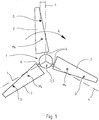
- the wind turbine has at least one rotor 1 with at least one rotor blade 2, vzw. with several, here with three rotor blades 2 on.
- the rotor blades 2 are operatively connected to a substantially horizontally disposed rotor shaft 3 via a rotor hub bearing.
- the rotor blades 2 are rotatable about a substantially radially aligned adjustment axis 4, wherein at least one adjusting device 5 acting on the adjustment axis 4 is provided for adjusting the rotor blades 2.
- the rotor 1 shown here of the wind turbine not shown in its entirety, here has three rotor blades 2.
- the wind turbine can have a plurality of rotor blades 2, for example four rotor blades or even only two, possibly even only one rotor blade 2.
- a rotational movement of the rotor shaft 3 is caused by the rotor blades 2 when it flows with the corresponding wind speed v wind , since the rotor blades 2 are effectively connected to the rotor shaft 3, which will be explained in more detail below.
- the rotor shaft 3 is arranged to extend substantially horizontally. This does not always have to be this way.
- the rotor shaft 3 is arranged slightly obliquely or even vertically. Vzw. However, the rotor shaft 3 is arranged to extend substantially horizontally and operatively connected to a generator, not shown here, to generate corresponding energy or electricity.
- the rotor blades 2 each have a stub shaft 6, which is rotatably mounted within a rotor hub 7.
- Fig. 1 is visible through the axis of the stub shaft 6 essentially defines the adjustment axis 4 or defined by the axis of the bearing 15, the adjustment axis 4.
- Out Fig.1 is also easy to see that the individual rotor blades 2, so the longitudinal axis of the rotor blades 2 do not coincide with the respective adjustment axis 4, but are arranged so that the respective pressure point D of the rotor blades 2 of the respective adjustment axis 4 lags behind during the rotation of the rotor 1 ,
- the rotational movement of the rotor 1 is in Fig. 1 represented by the corresponding arrow A.
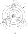
- Fig. 2 now shows the rotor 1 in a schematic representation of the side. Good to see are in the rotor hub 7 via the stub shafts 6 mounted rotor blades 2 and the schematically indicated here and partially shown rotor shaft 3. Due to the representation in Fig. 2 It can be seen that the adjustment axes 4 with respect to the rotor shaft 3, although substantially radially, vzw. However, the adjustment axes 4 of the rotor blades 2 are inclined slightly to the front substantially, so that the rotor blades 2 form an acute angle ⁇ with the general rotor plane. The arrangement of the rotor blades 2, the formation of an angle ⁇ and the formation of a trailing pressure point D have an adjusting torque in the direction of feathering during operation of the wind turbine.
- the adjusting device 5 has at least one cam disc 9 cooperating with a control disc 8 and the cam disc 9 is arranged such that the axis of rotation of the cam disc 9 coincides with the adjustment axis 4.
- the adjusting device 5 now has at least one control disk 8 and at least one cam 9, which interact with each other substantially frictionally, the disadvantages mentioned are avoided to a considerable extent.
- no additional belt element must be provided and the signs of wear are now substantially reduced, since the adjusting device 5 thus formed is substantially not susceptible to wear.
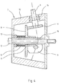
- FIGS Fig. 3 to 6 The preferred embodiment of the adjusting device 5 shown here, as shown in FIGS Fig. 3 to 6 can be seen, a control disk 8 and three cam 9.
- Fig. 4 shows that the control disk 8 is arranged on an axis 10 within the rotor hub 7 and is axially displaceable thereon.
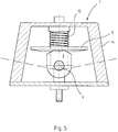
- the control disk 8 is rotatably mounted on the axle 10 by means of a bearing 11. It is from the Fig. 4 as well as from the Fig. 5 clearly recognize that the individual cams 9 are in frictional contact with the control disk 8.
- the control disk 8 is subjected to force by a spring element 12 in the direction of the cam disks 9.
- a spring element 12 in the direction of the cam disks 9.
- the spring element 12 is rotatably supported by means of a bearing 13, so that a rotation of the control disc 8 and also a corresponding rotation of the spring element 12 is made possible.
- the rotation axis of the control disk 8 corresponds to the axis of rotation of the rotor shaft 3.
- the adjusting device 5 consists essentially of a control disk 8 and three cams 9 and the bearing of the control disk 8 and the spring element 12 here.
- the number of cams 9 is substantially dependent on the number of rotor blades 2.
- the cams 9 are located respectively at the lower ends of the stub shafts 6 of the rotor blades 2 and are rotatably arranged here.
- the adjustment axes 4 of the respective rotor blades 2 are defined by the axes of the individual stub shafts 6.
- the respective stub shaft 6 is rotatably mounted within the peripheral wall 14 of the rotor hub 7.
- a corresponding bearing 15 is provided in each case.
- a corresponding number of shaft stumps 6 or cam disks 9 is now also provided. So it is quite conceivable that the adjusting device 5 therefore vzw. has two, four or more cams 9, which cooperate with the corresponding control disk 8. This is dependent on the respective embodiment of the wind power plant, in particular of the rotor 1.
- control disk 8 and the cam discs 9 may be different from the particular application and in particular depending on the forces occurring.
- steel and steel alloys but also corresponding other cast materials or corresponding mixtures as well as plastics in question. It is crucial that a punctual contact between the control disk 8 and the respective cam 9 is ensured. As a result, optimum storage of the control disk 8 and the cam 9 is possible.
- the design of the spring element 12, here as a helical compression spring has been found to be a preferred embodiment. But it is also conceivable, other spring elements, for example. Disc springs or the like. Provide here.
- control disk 8 rotatable and the spring element 12 are rotatably mounted, which will be explained in more detail below.
- wear and tear, in particular abrasion between the control disk 8 and cam 9 are significantly minimized, because due to the possibility of rotation of the control disk 8 together with the helical compression spring, it comes to a low Reibverschl accompany and a high control quality of the adjustment device. 5
- control disk 8 and cam 9 are therefore preferred materials that ensure good contact between the elements, ie in particular materials that ensure a good rolling of the cam 9 on the control disk 8. It is particularly advantageous that the entire adjusting device 5 is arranged substantially within the rotor hub 7 and therefore the individual elements are protected from the weather here. As a result, the necessary occurring contacts are not due the penetration of water, or other weather influences, such as icing or dirt reduces or interferes with the interaction of the elements.
- the Fig. 5 and 6 show a cam 9 from the side in a schematic representation.
- the upper portion of the cam 9 has a corresponding contour 9a.
- the contour 9a of the cam 9 has two extremes 16. These extremes 16 are used for the realization of the "zero position" or the neutral position of the cam 9 on the control disk 8. In other words, with the help of the extrema 16, the zero position of the cam 9 relative to the control disk 8 is clearly defined. This ensures optimal adjustment of the neutral position of the rotor blades 2.
- the adjusting device 5 is disposed or integrated within the rotor hub 7.
- the axis 10, on which the control disk 8 is mounted, is hollow, so that the rotor hub 7 by means of a connecting element 17, vzw. by means of a screw with the rotor shaft 3 for transmitting the torque of the rotor 1 is connectable.
- the adjusting device 5 is constructed such that it can be integrated on the one hand inside the rotor hub 7, but on the other hand, the rotor hub 7 in a simple manner to the rotor shaft 3 by a connecting element 17, vzw. a screw element with the rotor shaft 3 can be screwed. This increases the ease of installation of the entire wind turbine, since only one connecting element is required for the assembly, which is additionally of great advantage. Adjustment device 5 and rotor hub 7 therefore form an easily assembled module.
- the adjusting device 5 thus serves as a control and / or regulating element for controlling / regulating the power P or rotational speed n of the wind power plant.
- the adjusting device 5 serves as a control and / or regulating element for controlling / regulating the power P or rotational speed n of the wind power plant.
- cam disks 9, control disk 8 and spring element 12 are now designed and arranged such that the holding torque or holding forces can be transmitted to the rotor blades 2 in a corresponding manner, so that their position can be controlled or regulated accordingly. This may again on the Fig. 1 to get expelled.
- the pressure point D of the rotor blades 2 of the respective adjustment axis 4 lags behind. As a result, it comes with flow at a wind speed v wind > v nominal , shown in Fig. 2 , to a rotation of the rotor blades 2 about the adjustment axis 4, in particular because the pressure point D lies just outside the respective adjustment axis 4.
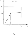
- Fig. 7 shows an increase in power Pnenn the wind turbine with increasing wind speed v wind to the value vnenn . Above the wind speed vnenn the wind turbine is therefore limited for safety reasons.
- Fig. 8 shows now that the adjustment device 5 is designed and / or formed such that the idle speed n rotor of the rotor 1 from a certain wind speed, here from the value v abr substantially only slightly increases, namely up to the wind speed v exr . Consequently, here the speed of the rotor is abmony from wind speed vr abr reasons of safety.
- the rotor blades 2 in the direction of the flag position also reduces the angle ⁇ .
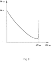
- Fig. 9 shows from the Abregeltician a steep drop in the holding torque M.
- the holding torque M decreases with increasing displacement angle phi until the end of Verstellwinkel Anlagens, where a steep increase takes place.
- This increase is realized by the contours 9a of the cams 9, namely by the "outer corner points", which are not specified.
- Fig. 9 Therefore, the "control characteristic" of the adjusting device 5 is therefore essentially defined by the formation / contour profile 9a of all cams and the spring element 12.
Landscapes
- Engineering & Computer Science (AREA)
- Life Sciences & Earth Sciences (AREA)
- Sustainable Development (AREA)
- Sustainable Energy (AREA)
- Chemical & Material Sciences (AREA)
- Combustion & Propulsion (AREA)
- Mechanical Engineering (AREA)
- General Engineering & Computer Science (AREA)
- Physics & Mathematics (AREA)
- Fluid Mechanics (AREA)
- Wind Motors (AREA)
Claims (20)
- Éolienne, comprenant au moins un rotor (1), le rotor (1) présentant au moins une pale de rotor (2), de préférence plusieurs pales de rotor (2), la pale de rotor (2) étant en liaison fonctionnelle avec un arbre de rotor (3), la pale de rotor (2) pouvant tourner autour d'un axe de réglage (4) orienté essentiellement radialement et, pour l'ajustement de la pale de rotor (2), au moins un dispositif de réglage (5) étant prévu, caractérisée en ce que le dispositif de réglage (5) présente au moins un disque de came (9) coopérant avec un disque de commande (8) et le disque de came (9) étant disposé de telle sorte que l'axe de rotation du disque de came (9) coïncide avec l'axe de réglage (4).
- Éolienne selon la revendication 1, caractérisée en ce que le disque de commande (8) est disposé sur un axe (10) à l'intérieur du moyeu de rotor (7) et peut être déplacé axialement.
- Éolienne selon la revendication 2, caractérisée en ce que le disque de commande (8) est supporté de manière rotative sur l'axe (10) à l'aide d'un palier (11).
- Éolienne selon l'une quelconque des revendications 1 à 3, caractérisée en ce que le disque de commande (8) est en contact d'engagement par friction avec le disque de came (9).
- Éolienne selon l'une quelconque des revendications 1 à 4, caractérisée en ce que le disque de commande (8) est sollicité par force par au moins un élément de ressort (12) dans la direction du disque de came (9).
- Éolienne selon la revendication 5, caractérisée en ce que l'élément de ressort (12) est supporté de manière rotative de telle sorte qu'une rotation du disque de commande (8) et de l'élément de ressort (12) soit possible.
- Éolienne selon l'une quelconque des revendications 1 à 6, caractérisée en ce que l'axe de rotation du disque de commande (8) correspond à l'axe de rotation de l'arbre de rotor (3).
- Éolienne selon l'une quelconque des revendications 1 à 7, caractérisée en ce que le disque de came (9) est disposé de manière solidaire en rotation à l'extrémité inférieure d'un bout d'arbre (6) de la pale de rotor (2) et l'axe de réglage (4) de la pale de rotor (2) est défini par l'axe du bout d'arbre (6).
- Éolienne selon la revendication 8, caractérisée en ce que le bout d'arbre (6) est supporté de manière rotative à l'intérieur de la paroi périphérique (14) du moyeu de rotor (7).
- Éolienne selon l'une quelconque des revendications 1 à 9, caractérisée en ce que l'allure du contour (9a) du disque de came (9) présente deux extrêmes (16) pour la réalisation de la position zéro ou de la position neutre du disque de came (9) sur le disque de commande (8).
- Éolienne selon la revendication 8, ou selon les revendications 8 et 10, caractérisée en ce que trois pales de rotor (2) sont prévues et les bouts d'arbre (6) des pales de rotor (2) sont supportés à rotation à l'intérieur de la paroi périphérique (14) du moyeu de rotor (7).
- Éolienne selon l'une quelconque des revendications 2 à 11, caractérisée en ce que le dispositif de réglage (5) est disposé à l'intérieur du moyeu de rotor (7).
- Éolienne selon l'une quelconque des revendications 2 à 12, caractérisée en ce que l'axe (10) du disque de commande (8) est réalisé sous forme creuse, de telle sorte que le moyeu de rotor (7) puisse être connecté à l'aide d'un élément de liaison (17) à l'arbre de rotor (3) en vue de transférer un couple.
- Éolienne selon l'une quelconque des revendications 1 à 13, caractérisée en ce que les pales de rotor (2) sont disposées de telle sorte que le point de pression respectif (D) des pales de rotor (2) suive l'axe de réglage (4) respectif.
- Éolienne selon l'une quelconque des revendications 1 à 14, caractérisée en ce que les axes de réglage (4) des pales de rotor (2) sont légèrement inclinés de telle sorte que les pales de rotor (2) forment un angle aigu (γ) avec le plan général du rotor.
- Éolienne selon l'une quelconque des revendications 1 à 15, caractérisée en ce qu'à l'aide du dispositif de réglage (5), une commande de puissance et/ou de vitesse de rotation de l'éolienne est possible.
- Éolienne selon l'une quelconque des revendications 5 à 16, caractérisée en ce que les disques de came (9), le disque de commande (8) et l'élément de ressort (12) sont réalisés et disposés de telle sorte que des couples de retenue (M) ou des forces de retenue puissent être transmis aux pales de rotor (2), de telle sorte que leur positionnement soit commandable.
- Éolienne selon l'une quelconque des revendications 5 à 17, caractérisée en ce que les disques de came (9), le disque de commande (8) et l'élément de ressort (12) sont réalisés et disposés de telle sorte que la plage angulaire de réglage des pales de rotor (2) soit déterminée par une caractéristique déterminée du couple de retenue (M) .
- Éolienne selon l'une quelconque des revendications 1 à 18, caractérisée en ce que le dispositif de réglage (5) est réalisé et/ou constitué de telle sorte que la puissance nominale (Pnenn) de l'éolienne reste constante à partir d'une vitesse du vent déterminé (vnenn), à savoir l'éolienne est réglée de manière à s'arrêter au-dessus de cette vitesse du vent déterminée (vnenn).
- Éolienne selon l'une quelconque des revendications 1 à 19, caractérisée en ce que le dispositif de réglage (5) est réalisé et/ou constitué de telle sorte que la vitesse de rotation de marche à vide (n) du rotor (1) soit réglée à partir d'une vitesse du vent déterminée (vabr).
Applications Claiming Priority (3)
| Application Number | Priority Date | Filing Date | Title |
|---|---|---|---|
| DE10226713A DE10226713B4 (de) | 2002-06-14 | 2002-06-14 | Windkraftanlage |
| DE10226713 | 2002-06-14 | ||
| PCT/DE2003/001868 WO2003106839A1 (fr) | 2002-06-14 | 2003-06-05 | Installation d'energie eolienne |
Publications (2)
| Publication Number | Publication Date |
|---|---|
| EP1516121A1 EP1516121A1 (fr) | 2005-03-23 |
| EP1516121B1 true EP1516121B1 (fr) | 2018-09-12 |
Family
ID=29719109
Family Applications (1)
| Application Number | Title | Priority Date | Filing Date |
|---|---|---|---|
| EP03759829.9A Expired - Lifetime EP1516121B1 (fr) | 2002-06-14 | 2003-06-05 | Installation d'energie eolienne |
Country Status (5)
| Country | Link |
|---|---|
| US (1) | US7137785B2 (fr) |
| EP (1) | EP1516121B1 (fr) |
| AU (1) | AU2003250744A1 (fr) |
| DE (1) | DE10226713B4 (fr) |
| WO (1) | WO2003106839A1 (fr) |
Families Citing this family (18)
| Publication number | Priority date | Publication date | Assignee | Title |
|---|---|---|---|---|
| DE102005014026A1 (de) * | 2005-03-23 | 2006-09-28 | Rudolf Eckart | Rotoranordnung für Windenergieanlagen |
| EP1904689A1 (fr) * | 2005-07-15 | 2008-04-02 | Energetech Australia Pty. Limited | Mécanisme de commande de pas |
| GB0609799D0 (en) * | 2006-05-18 | 2006-06-28 | Euro Projects Ltd | A turbine blade support assembly |
| US20110020136A1 (en) * | 2008-06-10 | 2011-01-27 | Mitsubishi Heavy Industries, Ltd. | Blade pitch-angle control apparatus and wind turbine generator |
| CA2709024A1 (fr) * | 2009-04-10 | 2010-10-10 | Mitsubishi Heavy Industries, Ltd. | Appareil de reglage de pas de pale pour aerogenerateur et generatrice eolienne |
| US8770934B2 (en) * | 2009-12-16 | 2014-07-08 | Hamilton Sundstrand Corporation | Teeter mechanism for a multiple-bladed wind turbine |
| US8622697B2 (en) | 2010-11-18 | 2014-01-07 | Hamilton Sundstrand Corporation | Ram air turbine bearing spacer |
| US9726149B2 (en) | 2011-01-18 | 2017-08-08 | Hamilton Sundstrand Corporation | Spiral bevel gear set for ram air turbine |
| EP2546517B1 (fr) * | 2011-07-13 | 2016-03-30 | ALSTOM Renewable Technologies | Rotor d'éolienne |
| DE102012013365A1 (de) * | 2012-06-22 | 2013-12-24 | Richard Strehler | Zentraler Pitchverstellung für Windkraftanlagen |
| CN103470712B (zh) * | 2013-09-23 | 2016-01-20 | 西北农林科技大学 | 一种速度自平衡装置 |
| CN104295449B (zh) * | 2014-09-23 | 2015-07-15 | 丁健威 | 一种叶片后置式风力发电装置 |
| DE102016111954A1 (de) * | 2016-06-30 | 2018-01-04 | Wobben Properties Gmbh | Pitchsystem einer Windenergieanlage und Windenergieanlage |
| NZ754040A (en) | 2016-12-02 | 2020-06-26 | Klaus Krieger | Wind power plant |
| DE202016007375U1 (de) | 2016-12-02 | 2017-01-23 | Martin van Egeren | Windkraftanlage |
| DE102016014339B4 (de) | 2016-12-02 | 2021-05-27 | Martin van Egeren | Windkraftanlage |
| DE102017104474A1 (de) | 2017-03-03 | 2018-09-06 | Wobben Properties Gmbh | Verstelleinheit für eine Azimutverstellung und/oder für eine Pitchverstellung einer Windenergieanlage und Verfahren |
| DE102017004909A1 (de) * | 2017-05-18 | 2018-11-22 | Enbreeze Gmbh | Vorrichtung zur Verstellung der Rotorblätter einer Strömungskraftanlage |
Family Cites Families (13)
| Publication number | Priority date | Publication date | Assignee | Title |
|---|---|---|---|---|
| FR1433734A (fr) * | 1965-04-26 | 1966-04-01 | Moteur éolien | |
| US3469633A (en) * | 1967-10-19 | 1969-09-30 | Gen Dynamics Corp | Control means for air driven turbines |
| US4124330A (en) * | 1974-10-09 | 1978-11-07 | United Technologies Corporation | Cam-operated pitch-change apparatus |
| IT1091536B (it) * | 1977-12-23 | 1985-07-06 | Fiat Spa | Dispositivo per la regolazione del passo delle pale di un motore eolico |
| DE2930062B1 (de) * | 1979-07-25 | 1980-02-14 | Maschf Augsburg Nuernberg Ag | Windrad mit einem auf einem Turm angeordneten ein- oder zweiblaettrigen Rotor |
| US4495423A (en) * | 1981-09-10 | 1985-01-22 | Felt Products Mfg. Co. | Wind energy conversion system |
| US4435646A (en) * | 1982-02-24 | 1984-03-06 | North Wind Power Company, Inc. | Wind turbine rotor control system |
| US4743163A (en) * | 1985-11-22 | 1988-05-10 | Sundstrand Corporation | Ram air turbine control system |
| DE3628626A1 (de) * | 1986-08-22 | 1988-02-25 | Peter Dipl Ing Frieden | Propellerwindmuehle mit erweitertem einsatzbereich |
| GB2233400A (en) * | 1989-06-20 | 1991-01-09 | George William James Bell | Automatic variable pitch propellor |
| DE4241631C2 (de) * | 1992-12-10 | 1994-11-24 | Peter Dipl Ing Frieden | Windkraftanlage |
| US6158953A (en) * | 1998-12-04 | 2000-12-12 | Lamont; John S | Wind turbine with variable position blades |
| DE19941630C1 (de) * | 1999-09-01 | 2001-03-08 | Pvo Engineering Ltd | Windenergieanlage mit verstellbaren Blättern |
-
2002
- 2002-06-14 DE DE10226713A patent/DE10226713B4/de not_active Expired - Fee Related
-
2003
- 2003-06-05 EP EP03759829.9A patent/EP1516121B1/fr not_active Expired - Lifetime
- 2003-06-05 WO PCT/DE2003/001868 patent/WO2003106839A1/fr not_active Ceased
- 2003-06-05 AU AU2003250744A patent/AU2003250744A1/en not_active Abandoned
-
2004
- 2004-12-14 US US11/011,387 patent/US7137785B2/en not_active Expired - Lifetime
Non-Patent Citations (1)
| Title |
|---|
| None * |
Also Published As
| Publication number | Publication date |
|---|---|
| US20050118026A1 (en) | 2005-06-02 |
| AU2003250744A1 (en) | 2003-12-31 |
| US7137785B2 (en) | 2006-11-21 |
| WO2003106839A1 (fr) | 2003-12-24 |
| DE10226713B4 (de) | 2004-07-08 |
| DE10226713A1 (de) | 2004-01-08 |
| EP1516121A1 (fr) | 2005-03-23 |
Similar Documents
| Publication | Publication Date | Title |
|---|---|---|
| EP1516121B1 (fr) | Installation d'energie eolienne | |
| EP1816346B1 (fr) | Dispositif de réglage du pas de l'hélice pour éolienne | |
| DE112008000344B4 (de) | Leistungsübertragungsvorrichtung und Herstellungsverfahren dafür | |
| EP1266137B1 (fr) | Palier pour une pale de rotor reglable d'une eolienne | |
| EP1440240B1 (fr) | Generateur pour une centrale hydroelectrique | |
| DE10003385A1 (de) | Windenergieanlage | |
| DE2632697A1 (de) | Windkraftmaschine | |
| EP1002949A2 (fr) | Eolienne à axe vertical | |
| DE3227700A1 (de) | Windenergiekonverter | |
| DE29706980U1 (de) | Gondel einer Windkraftanlage | |
| DE10219753A1 (de) | Hydrodynamische Bremse | |
| WO2014012591A1 (fr) | Installation génératrice d'énergie à flux | |
| EP4103835B1 (fr) | Rotor comprenant des pales de rotor | |
| DE3628626C2 (fr) | ||
| DE3117996C2 (fr) | ||
| DE10251388B4 (de) | Rotor einer Windkraftanlage | |
| DE102015104316A1 (de) | Wellgetriebe für einen Aktuator eines Lenksystems | |
| DE202012000907U1 (de) | Strömungskraftanlage | |
| DE202016007375U1 (de) | Windkraftanlage | |
| DE2948112A1 (de) | Vorrichtung zur selbsttaetigen regelung der drehzahl eines windrades | |
| WO2022006611A1 (fr) | Éolienne | |
| WO2021160335A1 (fr) | Ventilateur et véhicule comprenant un ventilateur | |
| DE102016014339B4 (de) | Windkraftanlage | |
| EP3548736B1 (fr) | Aérogénérateur | |
| AT413050B (de) | Generatoreinheit für eine wind- oder wasserkraftturbine |
Legal Events
| Date | Code | Title | Description |
|---|---|---|---|
| PUAI | Public reference made under article 153(3) epc to a published international application that has entered the european phase |
Free format text: ORIGINAL CODE: 0009012 |
|
| 17P | Request for examination filed |
Effective date: 20041216 |
|
| AK | Designated contracting states |
Kind code of ref document: A1 Designated state(s): AT BE BG CH CY CZ DE DK EE ES FI FR GB GR HU IE IT LI LU MC NL PT RO SE SI SK TR |
|
| AX | Request for extension of the european patent |
Extension state: AL LT LV MK |
|
| DAX | Request for extension of the european patent (deleted) | ||
| 17Q | First examination report despatched |
Effective date: 20100112 |
|
| STAA | Information on the status of an ep patent application or granted ep patent |
Free format text: STATUS: EXAMINATION IS IN PROGRESS |
|
| REG | Reference to a national code |
Ref country code: DE Ref legal event code: R079 Ref document number: 50315781 Country of ref document: DE Free format text: PREVIOUS MAIN CLASS: F03D0007020000 Ipc: F03D0007040000 |
|
| GRAP | Despatch of communication of intention to grant a patent |
Free format text: ORIGINAL CODE: EPIDOSNIGR1 |
|
| STAA | Information on the status of an ep patent application or granted ep patent |
Free format text: STATUS: GRANT OF PATENT IS INTENDED |
|
| RIC1 | Information provided on ipc code assigned before grant |
Ipc: F03D 7/04 20060101AFI20180115BHEP Ipc: F03D 7/02 20060101ALI20180115BHEP |
|
| INTG | Intention to grant announced |
Effective date: 20180215 |
|
| GRAS | Grant fee paid |
Free format text: ORIGINAL CODE: EPIDOSNIGR3 |
|
| GRAA | (expected) grant |
Free format text: ORIGINAL CODE: 0009210 |
|
| STAA | Information on the status of an ep patent application or granted ep patent |
Free format text: STATUS: THE PATENT HAS BEEN GRANTED |
|
| AK | Designated contracting states |
Kind code of ref document: B1 Designated state(s): AT BE BG CH CY CZ DE DK EE ES FI FR GB GR HU IE IT LI LU MC NL PT RO SE SI SK TR |
|
| REG | Reference to a national code |
Ref country code: GB Ref legal event code: FG4D Free format text: NOT ENGLISH |
|
| REG | Reference to a national code |
Ref country code: CH Ref legal event code: EP |
|
| REG | Reference to a national code |
Ref country code: IE Ref legal event code: FG4D Free format text: LANGUAGE OF EP DOCUMENT: GERMAN |
|
| REG | Reference to a national code |
Ref country code: DE Ref legal event code: R096 Ref document number: 50315781 Country of ref document: DE |
|
| REG | Reference to a national code |
Ref country code: AT Ref legal event code: REF Ref document number: 1040902 Country of ref document: AT Kind code of ref document: T Effective date: 20181015 |
|
| REG | Reference to a national code |
Ref country code: NL Ref legal event code: MP Effective date: 20180912 |
|
| REG | Reference to a national code |
Ref country code: DE Ref legal event code: R082 Ref document number: 50315781 Country of ref document: DE Representative=s name: HUEBSCH, KIRSCHNER & PARTNER, PATENTANWAELTE U, DE |
|
| PG25 | Lapsed in a contracting state [announced via postgrant information from national office to epo] |
Ref country code: GR Free format text: LAPSE BECAUSE OF FAILURE TO SUBMIT A TRANSLATION OF THE DESCRIPTION OR TO PAY THE FEE WITHIN THE PRESCRIBED TIME-LIMIT Effective date: 20181213 Ref country code: BG Free format text: LAPSE BECAUSE OF FAILURE TO SUBMIT A TRANSLATION OF THE DESCRIPTION OR TO PAY THE FEE WITHIN THE PRESCRIBED TIME-LIMIT Effective date: 20181212 Ref country code: FI Free format text: LAPSE BECAUSE OF FAILURE TO SUBMIT A TRANSLATION OF THE DESCRIPTION OR TO PAY THE FEE WITHIN THE PRESCRIBED TIME-LIMIT Effective date: 20180912 Ref country code: SE Free format text: LAPSE BECAUSE OF FAILURE TO SUBMIT A TRANSLATION OF THE DESCRIPTION OR TO PAY THE FEE WITHIN THE PRESCRIBED TIME-LIMIT Effective date: 20180912 |
|
| REG | Reference to a national code |
Ref country code: CH Ref legal event code: PK Free format text: BERICHTIGUNGEN |
|
| RIC2 | Information provided on ipc code assigned after grant |
Ipc: F03D 7/02 20060101ALI20180115BHEP Ipc: F03D 7/04 20060101AFI20180115BHEP |
|
| PG25 | Lapsed in a contracting state [announced via postgrant information from national office to epo] |
Ref country code: ES Free format text: LAPSE BECAUSE OF FAILURE TO SUBMIT A TRANSLATION OF THE DESCRIPTION OR TO PAY THE FEE WITHIN THE PRESCRIBED TIME-LIMIT Effective date: 20180912 |
|
| PG25 | Lapsed in a contracting state [announced via postgrant information from national office to epo] |
Ref country code: IT Free format text: LAPSE BECAUSE OF FAILURE TO SUBMIT A TRANSLATION OF THE DESCRIPTION OR TO PAY THE FEE WITHIN THE PRESCRIBED TIME-LIMIT Effective date: 20180912 Ref country code: RO Free format text: LAPSE BECAUSE OF FAILURE TO SUBMIT A TRANSLATION OF THE DESCRIPTION OR TO PAY THE FEE WITHIN THE PRESCRIBED TIME-LIMIT Effective date: 20180912 Ref country code: EE Free format text: LAPSE BECAUSE OF FAILURE TO SUBMIT A TRANSLATION OF THE DESCRIPTION OR TO PAY THE FEE WITHIN THE PRESCRIBED TIME-LIMIT Effective date: 20180912 Ref country code: CZ Free format text: LAPSE BECAUSE OF FAILURE TO SUBMIT A TRANSLATION OF THE DESCRIPTION OR TO PAY THE FEE WITHIN THE PRESCRIBED TIME-LIMIT Effective date: 20180912 Ref country code: NL Free format text: LAPSE BECAUSE OF FAILURE TO SUBMIT A TRANSLATION OF THE DESCRIPTION OR TO PAY THE FEE WITHIN THE PRESCRIBED TIME-LIMIT Effective date: 20180912 |
|
| PG25 | Lapsed in a contracting state [announced via postgrant information from national office to epo] |
Ref country code: PT Free format text: LAPSE BECAUSE OF FAILURE TO SUBMIT A TRANSLATION OF THE DESCRIPTION OR TO PAY THE FEE WITHIN THE PRESCRIBED TIME-LIMIT Effective date: 20190112 Ref country code: SK Free format text: LAPSE BECAUSE OF FAILURE TO SUBMIT A TRANSLATION OF THE DESCRIPTION OR TO PAY THE FEE WITHIN THE PRESCRIBED TIME-LIMIT Effective date: 20180912 |
|
| REG | Reference to a national code |
Ref country code: DE Ref legal event code: R097 Ref document number: 50315781 Country of ref document: DE |
|
| PLBE | No opposition filed within time limit |
Free format text: ORIGINAL CODE: 0009261 |
|
| STAA | Information on the status of an ep patent application or granted ep patent |
Free format text: STATUS: NO OPPOSITION FILED WITHIN TIME LIMIT |
|
| PG25 | Lapsed in a contracting state [announced via postgrant information from national office to epo] |
Ref country code: DK Free format text: LAPSE BECAUSE OF FAILURE TO SUBMIT A TRANSLATION OF THE DESCRIPTION OR TO PAY THE FEE WITHIN THE PRESCRIBED TIME-LIMIT Effective date: 20180912 |
|
| 26N | No opposition filed |
Effective date: 20190613 |
|
| PG25 | Lapsed in a contracting state [announced via postgrant information from national office to epo] |
Ref country code: SI Free format text: LAPSE BECAUSE OF FAILURE TO SUBMIT A TRANSLATION OF THE DESCRIPTION OR TO PAY THE FEE WITHIN THE PRESCRIBED TIME-LIMIT Effective date: 20180912 |
|
| PG25 | Lapsed in a contracting state [announced via postgrant information from national office to epo] |
Ref country code: MC Free format text: LAPSE BECAUSE OF FAILURE TO SUBMIT A TRANSLATION OF THE DESCRIPTION OR TO PAY THE FEE WITHIN THE PRESCRIBED TIME-LIMIT Effective date: 20180912 |
|
| REG | Reference to a national code |
Ref country code: CH Ref legal event code: PL |
|
| REG | Reference to a national code |
Ref country code: BE Ref legal event code: MM Effective date: 20190630 |
|
| PG25 | Lapsed in a contracting state [announced via postgrant information from national office to epo] |
Ref country code: TR Free format text: LAPSE BECAUSE OF FAILURE TO SUBMIT A TRANSLATION OF THE DESCRIPTION OR TO PAY THE FEE WITHIN THE PRESCRIBED TIME-LIMIT Effective date: 20180912 |
|
| PG25 | Lapsed in a contracting state [announced via postgrant information from national office to epo] |
Ref country code: IE Free format text: LAPSE BECAUSE OF NON-PAYMENT OF DUE FEES Effective date: 20190605 |
|
| PG25 | Lapsed in a contracting state [announced via postgrant information from national office to epo] |
Ref country code: LI Free format text: LAPSE BECAUSE OF NON-PAYMENT OF DUE FEES Effective date: 20190630 Ref country code: LU Free format text: LAPSE BECAUSE OF NON-PAYMENT OF DUE FEES Effective date: 20190605 Ref country code: BE Free format text: LAPSE BECAUSE OF NON-PAYMENT OF DUE FEES Effective date: 20190630 Ref country code: CH Free format text: LAPSE BECAUSE OF NON-PAYMENT OF DUE FEES Effective date: 20190630 |
|
| REG | Reference to a national code |
Ref country code: AT Ref legal event code: MM01 Ref document number: 1040902 Country of ref document: AT Kind code of ref document: T Effective date: 20190605 |
|
| PG25 | Lapsed in a contracting state [announced via postgrant information from national office to epo] |
Ref country code: AT Free format text: LAPSE BECAUSE OF NON-PAYMENT OF DUE FEES Effective date: 20190605 |
|
| PG25 | Lapsed in a contracting state [announced via postgrant information from national office to epo] |
Ref country code: CY Free format text: LAPSE BECAUSE OF FAILURE TO SUBMIT A TRANSLATION OF THE DESCRIPTION OR TO PAY THE FEE WITHIN THE PRESCRIBED TIME-LIMIT Effective date: 20180912 |
|
| PG25 | Lapsed in a contracting state [announced via postgrant information from national office to epo] |
Ref country code: HU Free format text: LAPSE BECAUSE OF FAILURE TO SUBMIT A TRANSLATION OF THE DESCRIPTION OR TO PAY THE FEE WITHIN THE PRESCRIBED TIME-LIMIT; INVALID AB INITIO Effective date: 20030605 |
|
| PGFP | Annual fee paid to national office [announced via postgrant information from national office to epo] |
Ref country code: FR Payment date: 20210621 Year of fee payment: 19 |
|
| PGFP | Annual fee paid to national office [announced via postgrant information from national office to epo] |
Ref country code: GB Payment date: 20210623 Year of fee payment: 19 |
|
| PGFP | Annual fee paid to national office [announced via postgrant information from national office to epo] |
Ref country code: DE Payment date: 20210714 Year of fee payment: 19 |
|
| REG | Reference to a national code |
Ref country code: DE Ref legal event code: R119 Ref document number: 50315781 Country of ref document: DE |
|
| GBPC | Gb: european patent ceased through non-payment of renewal fee |
Effective date: 20220605 |
|
| PG25 | Lapsed in a contracting state [announced via postgrant information from national office to epo] |
Ref country code: FR Free format text: LAPSE BECAUSE OF NON-PAYMENT OF DUE FEES Effective date: 20220630 |
|
| PG25 | Lapsed in a contracting state [announced via postgrant information from national office to epo] |
Ref country code: GB Free format text: LAPSE BECAUSE OF NON-PAYMENT OF DUE FEES Effective date: 20220605 Ref country code: DE Free format text: LAPSE BECAUSE OF NON-PAYMENT OF DUE FEES Effective date: 20230103 |