EP1515864B1 - Method and device for limiting the driving speed of a motor vehicle - Google Patents
Method and device for limiting the driving speed of a motor vehicle Download PDFInfo
- Publication number
- EP1515864B1 EP1515864B1 EP02790261A EP02790261A EP1515864B1 EP 1515864 B1 EP1515864 B1 EP 1515864B1 EP 02790261 A EP02790261 A EP 02790261A EP 02790261 A EP02790261 A EP 02790261A EP 1515864 B1 EP1515864 B1 EP 1515864B1
- Authority
- EP
- European Patent Office
- Prior art keywords
- speed
- vehicle
- fuel consumption
- driving speed
- maximum
- Prior art date
- Legal status (The legal status is an assumption and is not a legal conclusion. Google has not performed a legal analysis and makes no representation as to the accuracy of the status listed.)
- Expired - Lifetime
Links
- 238000000034 method Methods 0.000 title claims description 16
- 239000000446 fuel Substances 0.000 claims description 45
- 230000001133 acceleration Effects 0.000 claims description 11
- XDDAORKBJWWYJS-UHFFFAOYSA-N glyphosate Chemical group OC(=O)CNCP(O)(O)=O XDDAORKBJWWYJS-UHFFFAOYSA-N 0.000 claims description 10
- 230000001419 dependent effect Effects 0.000 claims description 9
- 230000005540 biological transmission Effects 0.000 claims description 7
- 238000010586 diagram Methods 0.000 claims description 6
- 230000009849 deactivation Effects 0.000 description 4
- 230000008901 benefit Effects 0.000 description 3
- 230000004913 activation Effects 0.000 description 2
- 238000005096 rolling process Methods 0.000 description 2
- 230000000694 effects Effects 0.000 description 1
- 230000004044 response Effects 0.000 description 1
- 238000001228 spectrum Methods 0.000 description 1
Images

Classifications
-
- B—PERFORMING OPERATIONS; TRANSPORTING
- B60—VEHICLES IN GENERAL
- B60K—ARRANGEMENT OR MOUNTING OF PROPULSION UNITS OR OF TRANSMISSIONS IN VEHICLES; ARRANGEMENT OR MOUNTING OF PLURAL DIVERSE PRIME-MOVERS IN VEHICLES; AUXILIARY DRIVES FOR VEHICLES; INSTRUMENTATION OR DASHBOARDS FOR VEHICLES; ARRANGEMENTS IN CONNECTION WITH COOLING, AIR INTAKE, GAS EXHAUST OR FUEL SUPPLY OF PROPULSION UNITS IN VEHICLES
- B60K31/00—Vehicle fittings, acting on a single sub-unit only, for automatically controlling vehicle speed, i.e. preventing speed from exceeding an arbitrarily established velocity or maintaining speed at a particular velocity, as selected by the vehicle operator
- B60K31/02—Vehicle fittings, acting on a single sub-unit only, for automatically controlling vehicle speed, i.e. preventing speed from exceeding an arbitrarily established velocity or maintaining speed at a particular velocity, as selected by the vehicle operator including electrically actuated servomechanism including an electric control system or a servomechanism in which the vehicle velocity affecting element is actuated electrically
- B60K31/04—Vehicle fittings, acting on a single sub-unit only, for automatically controlling vehicle speed, i.e. preventing speed from exceeding an arbitrarily established velocity or maintaining speed at a particular velocity, as selected by the vehicle operator including electrically actuated servomechanism including an electric control system or a servomechanism in which the vehicle velocity affecting element is actuated electrically and means for comparing one electrical quantity, e.g. voltage, pulse, waveform, flux, or the like, with another quantity of a like kind, which comparison means is involved in the development of an electrical signal which is fed into the controlling means
-
- B—PERFORMING OPERATIONS; TRANSPORTING
- B60—VEHICLES IN GENERAL
- B60W—CONJOINT CONTROL OF VEHICLE SUB-UNITS OF DIFFERENT TYPE OR DIFFERENT FUNCTION; CONTROL SYSTEMS SPECIALLY ADAPTED FOR HYBRID VEHICLES; ROAD VEHICLE DRIVE CONTROL SYSTEMS FOR PURPOSES NOT RELATED TO THE CONTROL OF A PARTICULAR SUB-UNIT
- B60W30/00—Purposes of road vehicle drive control systems not related to the control of a particular sub-unit, e.g. of systems using conjoint control of vehicle sub-units, or advanced driver assistance systems for ensuring comfort, stability and safety or drive control systems for propelling or retarding the vehicle
- B60W30/14—Adaptive cruise control
- B60W30/143—Speed control
- B60W30/146—Speed limiting
-
- B—PERFORMING OPERATIONS; TRANSPORTING
- B60—VEHICLES IN GENERAL
- B60L—PROPULSION OF ELECTRICALLY-PROPELLED VEHICLES; SUPPLYING ELECTRIC POWER FOR AUXILIARY EQUIPMENT OF ELECTRICALLY-PROPELLED VEHICLES; ELECTRODYNAMIC BRAKE SYSTEMS FOR VEHICLES IN GENERAL; MAGNETIC SUSPENSION OR LEVITATION FOR VEHICLES; MONITORING OPERATING VARIABLES OF ELECTRICALLY-PROPELLED VEHICLES; ELECTRIC SAFETY DEVICES FOR ELECTRICALLY-PROPELLED VEHICLES
- B60L2240/00—Control parameters of input or output; Target parameters
- B60L2240/40—Drive Train control parameters
- B60L2240/44—Drive Train control parameters related to combustion engines
- B60L2240/441—Speed
-
- B—PERFORMING OPERATIONS; TRANSPORTING
- B60—VEHICLES IN GENERAL
- B60L—PROPULSION OF ELECTRICALLY-PROPELLED VEHICLES; SUPPLYING ELECTRIC POWER FOR AUXILIARY EQUIPMENT OF ELECTRICALLY-PROPELLED VEHICLES; ELECTRODYNAMIC BRAKE SYSTEMS FOR VEHICLES IN GENERAL; MAGNETIC SUSPENSION OR LEVITATION FOR VEHICLES; MONITORING OPERATING VARIABLES OF ELECTRICALLY-PROPELLED VEHICLES; ELECTRIC SAFETY DEVICES FOR ELECTRICALLY-PROPELLED VEHICLES
- B60L2240/00—Control parameters of input or output; Target parameters
- B60L2240/40—Drive Train control parameters
- B60L2240/44—Drive Train control parameters related to combustion engines
- B60L2240/443—Torque
-
- B—PERFORMING OPERATIONS; TRANSPORTING
- B60—VEHICLES IN GENERAL
- B60L—PROPULSION OF ELECTRICALLY-PROPELLED VEHICLES; SUPPLYING ELECTRIC POWER FOR AUXILIARY EQUIPMENT OF ELECTRICALLY-PROPELLED VEHICLES; ELECTRODYNAMIC BRAKE SYSTEMS FOR VEHICLES IN GENERAL; MAGNETIC SUSPENSION OR LEVITATION FOR VEHICLES; MONITORING OPERATING VARIABLES OF ELECTRICALLY-PROPELLED VEHICLES; ELECTRIC SAFETY DEVICES FOR ELECTRICALLY-PROPELLED VEHICLES
- B60L2240/00—Control parameters of input or output; Target parameters
- B60L2240/40—Drive Train control parameters
- B60L2240/48—Drive Train control parameters related to transmissions
- B60L2240/486—Operating parameters
-
- B—PERFORMING OPERATIONS; TRANSPORTING
- B60—VEHICLES IN GENERAL
- B60W—CONJOINT CONTROL OF VEHICLE SUB-UNITS OF DIFFERENT TYPE OR DIFFERENT FUNCTION; CONTROL SYSTEMS SPECIALLY ADAPTED FOR HYBRID VEHICLES; ROAD VEHICLE DRIVE CONTROL SYSTEMS FOR PURPOSES NOT RELATED TO THE CONTROL OF A PARTICULAR SUB-UNIT
- B60W50/00—Details of control systems for road vehicle drive control not related to the control of a particular sub-unit, e.g. process diagnostic or vehicle driver interfaces
- B60W2050/0001—Details of the control system
- B60W2050/0043—Signal treatments, identification of variables or parameters, parameter estimation or state estimation
- B60W2050/0052—Filtering, filters
-
- B—PERFORMING OPERATIONS; TRANSPORTING
- B60—VEHICLES IN GENERAL
- B60W—CONJOINT CONTROL OF VEHICLE SUB-UNITS OF DIFFERENT TYPE OR DIFFERENT FUNCTION; CONTROL SYSTEMS SPECIALLY ADAPTED FOR HYBRID VEHICLES; ROAD VEHICLE DRIVE CONTROL SYSTEMS FOR PURPOSES NOT RELATED TO THE CONTROL OF A PARTICULAR SUB-UNIT
- B60W2510/00—Input parameters relating to a particular sub-units
- B60W2510/06—Combustion engines, Gas turbines
- B60W2510/0638—Engine speed
-
- B—PERFORMING OPERATIONS; TRANSPORTING
- B60—VEHICLES IN GENERAL
- B60W—CONJOINT CONTROL OF VEHICLE SUB-UNITS OF DIFFERENT TYPE OR DIFFERENT FUNCTION; CONTROL SYSTEMS SPECIALLY ADAPTED FOR HYBRID VEHICLES; ROAD VEHICLE DRIVE CONTROL SYSTEMS FOR PURPOSES NOT RELATED TO THE CONTROL OF A PARTICULAR SUB-UNIT
- B60W2510/00—Input parameters relating to a particular sub-units
- B60W2510/06—Combustion engines, Gas turbines
- B60W2510/0657—Engine torque
-
- B—PERFORMING OPERATIONS; TRANSPORTING
- B60—VEHICLES IN GENERAL
- B60W—CONJOINT CONTROL OF VEHICLE SUB-UNITS OF DIFFERENT TYPE OR DIFFERENT FUNCTION; CONTROL SYSTEMS SPECIALLY ADAPTED FOR HYBRID VEHICLES; ROAD VEHICLE DRIVE CONTROL SYSTEMS FOR PURPOSES NOT RELATED TO THE CONTROL OF A PARTICULAR SUB-UNIT
- B60W2530/00—Input parameters relating to vehicle conditions or values, not covered by groups B60W2510/00 or B60W2520/00
- B60W2530/10—Weight
-
- B—PERFORMING OPERATIONS; TRANSPORTING
- B60—VEHICLES IN GENERAL
- B60W—CONJOINT CONTROL OF VEHICLE SUB-UNITS OF DIFFERENT TYPE OR DIFFERENT FUNCTION; CONTROL SYSTEMS SPECIALLY ADAPTED FOR HYBRID VEHICLES; ROAD VEHICLE DRIVE CONTROL SYSTEMS FOR PURPOSES NOT RELATED TO THE CONTROL OF A PARTICULAR SUB-UNIT
- B60W2530/00—Input parameters relating to vehicle conditions or values, not covered by groups B60W2510/00 or B60W2520/00
- B60W2530/16—Driving resistance
-
- B—PERFORMING OPERATIONS; TRANSPORTING
- B60—VEHICLES IN GENERAL
- B60W—CONJOINT CONTROL OF VEHICLE SUB-UNITS OF DIFFERENT TYPE OR DIFFERENT FUNCTION; CONTROL SYSTEMS SPECIALLY ADAPTED FOR HYBRID VEHICLES; ROAD VEHICLE DRIVE CONTROL SYSTEMS FOR PURPOSES NOT RELATED TO THE CONTROL OF A PARTICULAR SUB-UNIT
- B60W2540/00—Input parameters relating to occupants
- B60W2540/10—Accelerator pedal position
- B60W2540/106—Rate of change
-
- B—PERFORMING OPERATIONS; TRANSPORTING
- B60—VEHICLES IN GENERAL
- B60W—CONJOINT CONTROL OF VEHICLE SUB-UNITS OF DIFFERENT TYPE OR DIFFERENT FUNCTION; CONTROL SYSTEMS SPECIALLY ADAPTED FOR HYBRID VEHICLES; ROAD VEHICLE DRIVE CONTROL SYSTEMS FOR PURPOSES NOT RELATED TO THE CONTROL OF A PARTICULAR SUB-UNIT
- B60W2710/00—Output or target parameters relating to a particular sub-units
- B60W2710/10—Change speed gearings
- B60W2710/1061—Output power
-
- Y—GENERAL TAGGING OF NEW TECHNOLOGICAL DEVELOPMENTS; GENERAL TAGGING OF CROSS-SECTIONAL TECHNOLOGIES SPANNING OVER SEVERAL SECTIONS OF THE IPC; TECHNICAL SUBJECTS COVERED BY FORMER USPC CROSS-REFERENCE ART COLLECTIONS [XRACs] AND DIGESTS
- Y02—TECHNOLOGIES OR APPLICATIONS FOR MITIGATION OR ADAPTATION AGAINST CLIMATE CHANGE
- Y02T—CLIMATE CHANGE MITIGATION TECHNOLOGIES RELATED TO TRANSPORTATION
- Y02T10/00—Road transport of goods or passengers
- Y02T10/10—Internal combustion engine [ICE] based vehicles
- Y02T10/40—Engine management systems
-
- Y—GENERAL TAGGING OF NEW TECHNOLOGICAL DEVELOPMENTS; GENERAL TAGGING OF CROSS-SECTIONAL TECHNOLOGIES SPANNING OVER SEVERAL SECTIONS OF THE IPC; TECHNICAL SUBJECTS COVERED BY FORMER USPC CROSS-REFERENCE ART COLLECTIONS [XRACs] AND DIGESTS
- Y02—TECHNOLOGIES OR APPLICATIONS FOR MITIGATION OR ADAPTATION AGAINST CLIMATE CHANGE
- Y02T—CLIMATE CHANGE MITIGATION TECHNOLOGIES RELATED TO TRANSPORTATION
- Y02T10/00—Road transport of goods or passengers
- Y02T10/80—Technologies aiming to reduce greenhouse gasses emissions common to all road transportation technologies
- Y02T10/84—Data processing systems or methods, management, administration
-
- Y—GENERAL TAGGING OF NEW TECHNOLOGICAL DEVELOPMENTS; GENERAL TAGGING OF CROSS-SECTIONAL TECHNOLOGIES SPANNING OVER SEVERAL SECTIONS OF THE IPC; TECHNICAL SUBJECTS COVERED BY FORMER USPC CROSS-REFERENCE ART COLLECTIONS [XRACs] AND DIGESTS
- Y10—TECHNICAL SUBJECTS COVERED BY FORMER USPC
- Y10S—TECHNICAL SUBJECTS COVERED BY FORMER USPC CROSS-REFERENCE ART COLLECTIONS [XRACs] AND DIGESTS
- Y10S477/00—Interrelated power delivery controls, including engine control
- Y10S477/902—Control signal is engine parameter other than manifold pressure or fuel control
Definitions
- the invention is based on a method and a device for limiting the travel speed of a motor vehicle.
- Another method is from the DE-A-10024231 known.
- the inventive method and the device according to the invention for limiting the travel speed of a motor vehicle with the features of the independent claims have the advantage that the vehicle speed is limited to a maximum value at which a predetermined for stationary driving speed maximum fuel consumption is not exceeded. In this way, an adjustable stationary fuel consumption can be maintained without limiting short-term accelerations. Thus, an economical driving can be automated according to the driver of the vehicle.
- the maximum value for the driving speed is determined from a maximum driving force of the vehicle, which results from the ratio between the predetermined maximum fuel consumption and a specific fuel consumption of the engine at the current operating point, by means of an inverse characteristic curve for a speed-dependent component of the driving resistance becomes.
- the maximum value for the driving speed can be determined particularly simple and inexpensive.
- the maximum driving force is corrected by a speed-independent component of the driving resistance. In this way, the accuracy of determining the maximum value for the driving speed is increased.
- a further advantage is that the speed-independent component of the driving resistance is filtered, in particular with a first-order low-pass filter. In this way, noise effects in the calculation of the speed-independent component of the driving resistance can be largely smoothed.
- the limitation of the driving speed in dependence on the predetermined maximum fuel consumption is only performed when the gradient of an accelerator pedal position falls below a predetermined value or a kick-down function is deactivated. In this way, it is ensured that in driving situations in which the driver primarily depends on achieving the highest possible driving speed, the fuel consumption-dependent limitation of the driving speed is overridden. Thus, the driving safety, for example in overtaking, guaranteed.
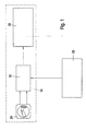
- FIG. 1 shows an arrangement for limiting the speed in a motor vehicle in the form of a block diagram.
- a device 10 for limiting the driving speed of the motor vehicle is provided.
- the device 10 comprises an input / operating unit 20, which is connected to means 15 for determining a maximum value vmaxbe, to which the driving speed is to be limited.
- the maximum value vmaxbe for the driving speed is given by the means 15 to means 30, which realize the actual speed limiting function.
- the means 30 ensure that the current driving speed of the motor vehicle does not exceed the maximum value vmaxbe for the driving speed. about the input / operating unit 20, the driver of the motor vehicle can specify a maximum fuel consumption Besoll for a stationary driving speed.
- the driver at the input / operating unit 20 can activate the means 15 in such a way that they determine the maximum value vmaxbe for the driving speed as a function of the maximum fuel consumption Besoll predetermined for the stationary driving speed.
- the input / operating unit 20 generates an activation signal "ON”.
- the driver at the input / operating unit 20 can deactivate the means 15 such that the maximum value vmaxbe for the driving speed is not determined as a function of the maximum fuel consumption Besoll predetermined for the stationary driving speed.
- the means 15 for input / output generates a deactivation signal "OFF".
- an engine control 25 which includes values for a transmission ratio factor, an engine speed nmot, an engine actual moment Miist, an actual acceleration aist of the vehicle, an actual speed vist of the vehicle, and a bit B_kdown, the device 10 and the means 15 indicates whether a kick-down of the vehicle has been operated using an automatic transmission.
- the determination of the values for the transmission ratio factor üist, the engine speed nmot, the actual engine torque Miist, the actual acceleration aist and the actual speed vist is carried out in a manner known from the prior art.
- the kick-down B_kdown bit is set upon actuation of the kick-down and is otherwise reset.
- an engine consumption map 35 is provided, the engine speed nmot and the Motoristmoment Miist are supplied as input variables.
- the output quantity is a specific fuel consumption BEENG of the engine of the vehicle in the current operating point, which is characterized by the engine speed nmot and the Motoristmoment Miist.
- the engine consumption map 35 is determined by default for each engine by its manufacturer and is therefore known from the prior art.
- the specific fuel consumption BEENG of the engine is multiplied by the transmission ratio factor ⁇ .
- the multiplication result is multiplied in a second connection point 45 with a wheel radius r Rad of the wheels of the vehicle, wherein the wheel radius r wheel in the means 15 known and stored there or known in the engine control 25 and can be transferred from there to the means 15.
- the multiplication result is identified in FIG. 2 by bePT and is fed to a third node 50.
- the quotient is formed from the maximum fuel consumption Besoll predetermined for stationary vehicle speed and the multiplication result bePT, so that a maximum drive force F BEsetpoint of the vehicle results as follows:
- F Besoll Besoll / bePT
- the actual engine torque Miist is also supplied to a fourth node 55 where it is multiplied by the transmission ratio factor ⁇ .
- the multiplication result is fed to a fifth node 60 where it is multiplied by the wheel radius r Rad .
- the multiplication result is the current driving force FAN of the vehicle.
- a sixth connection point 65 the actual acceleration aist of the vehicle with the vehicle mass MFzg multiplied.
- the multiplication result is the inertia force T of the vehicle.
- the vehicle mass MFzg can be known in the means 15 and stored there. Alternatively, the vehicle mass MFzg may be known in the engine control 25 and transmitted from there to the means 15.
- the actual speed vist of the vehicle is fed to a first characteristic 85 as an input variable.
- the first characteristic 85 delivers from the actual speed vist a speed-dependent component fv of the driving resistance of the vehicle.
- the inertial force T and the speed-dependent component fv of the driving resistance are added together.
- the addition result is subtracted from the current driving force FAN of the vehicle at an eighth node 75.
- the subtraction result is fed to a filter 5 in order to smooth noise influences on the measured value for the actual acceleration a and to prevent rapid changes of the maximum value vmaxbe for the driving speed.
- the filter 5 may be, for example, a first order low pass filter.
- the smoothed output signal of the filter 5 is fed as a speed-independent component F ⁇ of the driving resistance to a ninth connection point 80 and there subtracted from the maximum driving force F BEsoll .
- the subtraction result is fed as input to a second characteristic curve 90, which is inverse to the first characteristic curve 85 and supplies a speed value fv -1 , which is supplied to a first input 105 of a controlled switch 100.
- a second input 110 of the controlled switch 100 is supplied with a predetermined absolute maximum speed VMAX, which is either permanently preset or can likewise be preset by the user at the input / operating unit 20.
- the controlled switch 100 is controlled via an OR gate 95, to which the deactivation signal "OFF" and the bit B_kdown for the kick-down are supplied as input variables.
- B_kdown OR gate 95 is set, that is, the kick-down is pressed or the driver has disabled at the input / operating unit 20, the specification of the maximum value vmaxbe for the vehicle speed in function of the preset for stationary vehicle speed maximum fuel consumption Besoll
- the output of the OR gate is set and causes the controlled switch 100 to connect the second input 110 to the output 115 of the controlled switch 100.
- the predetermined absolute maximum speed VMAX the means 30th fed.
- the output of the OR gate 95 is reset, ie neither the kick-down is actuated nor deactivated by the driver at the input / operating unit 20, the determination of the maximum value vmaxbe for the driving speed as a function of the maximum fuel consumption Besoll given for stationary driving speed
- the reset output of the OR gate 95 causes the controlled switch 100 to connect the first input 105 to the output 115, so that the output fv -1 of the second characteristic 90 is supplied to the means 30 as the maximum value vmaxbe for the vehicle speed becomes.
- the speed limit function implemented by the means 30 is a function of the vehicle longitudinal movement, which allows the driver to specify a maximum value vmaxbe for the driving speed which is not to be exceeded by the actual speed vist of the vehicle. This uses both the driving safety, as well as the fuel consumption. If the driver wants to use the speed limiting function to limit himself to a desired fuel consumption, this is not possible by the specification of the maximum value vmaxbe for the driving speed alone, since the fuel consumption also depends on speed-independent parameters, such as the slope, the engine operating point or the headwind.
- the fuel consumption in this embodiment is a fuel line consumption, ie a fuel consumption per traveled distance, so for example, the fuel consumption per 100 km traveled distance.
- the maximum value vmaxbe for the driving speed is calculated as the output fv- 1 of the second characteristic curve 90 such that the maximum fuel consumption Besoll specified for stationary driving speed is not exceeded.
- the goal is to solve equation (2) according to the actual speed vist.
- the maximum value vmaxbe for the driving speed valid for the given maximum fuel consumption Besoll is obtained.
- the vehicle acceleration below the maximum value vmaxbe for the driving speed should not be limited as a function of the specified maximum fuel consumption Besoll, in order not to endanger the agility of the vehicle. Therefore, only the maximum value vmaxbe is calculated for the vehicle speed that results in the stationary drive case, ie, in which the actual acceleration aist of the vehicle is zero and the braking force Fbr of the vehicle in equation (2) is also equal to zero.
- the driving resistance of the vehicle consists of the speed-dependent component fv, resulting from the Rolling resistance Froll and the drag Fair in equation (2) composed, as well as from the velocity independent portion F ⁇ , which consists of the pitch resistance and the force by headwind.
- the right side of equation (4) corresponds to the mean force produced by the rolling resistance Froll and the drag Fair.
- the quotient on the left side of the equation may be interpreted as a driving force F Be of the vehicle multiplied by the transmission ratio factor ⁇ t and the wheel radius r Rad from the actual value Be of the fuel consumption per distance covered relative to the specific fuel consumption BeENG of the engine in the current one Operating point results.
- the right-hand side of equation (4) can be determined in a vehicle experiment as the first characteristic curve fv (vist) over the actual speed vist. The determination can be made as follows:
- the vehicle is operated in calm weather, on a level road, at stationary actual speed vist.
- the current driving force FAN of the vehicle is then determined from the motor instantaneous moment Miist, as shown in FIG. 2 with the aid of the fourth linking point 55 and the fifth linking point 60.
- the described vehicle experiment is carried out for several actual speeds vist of the vehicle, which is the entire spectrum of the possible actual speeds Cover the vehicle with sufficient density. In this way, the first characteristic curve 85 is formed.
- the actual speeds vist of the vehicle then represent the interpolation points of the first characteristic curve 85.
- the driving resistances as a function of the actual speed vist of the vehicle are increasing monotonously. Therefore, the first characteristic 85 corresponding to the function fv (vist) can be inverted. The inversion of the first characteristic curve 85 then corresponds to the function fv -1 (vist) and corresponds to the second characteristic curve 90.
- the engine consumption map 35 is described in Equation (7) as BeENG (nmot, Miist) and is determined by default for each engine by its manufacturer as described, and is thus set in the means 15 in a manner known in the art.
- BeENG nomot, Miist
- the current driving force FAN of the vehicle may be formed from the actual motor torque Miist, the gear ratio factor ⁇ and the wheel radius R Rad in the manner described according to FIG.
- the speed-independent component F ⁇ of the driving resistance according to FIG. 2 is filtered, for example by a first-order low-pass filter.
- the limitation of the driving speed in dependence on the predetermined maximum fuel consumption Besoll is only carried out if a kick-down function is deactivated, ie the bit B_kdown is reset.
- the limitation of the driving speed depending on the predetermined maximum fuel consumption Besoll may be provided to carry out the limitation of the driving speed depending on the predetermined maximum fuel consumption Besoll only when the gradient of an accelerator pedal position falls below a predetermined value. Exceeds the gradient of the accelerator pedal position the predetermined value, it is recognized that the driver wants to accelerate as fast as possible, similar to the kick-down function, so that in this case, the limitation of Driving speed depending on the given maximum fuel consumption Besoll to be abandoned and instead the driving speed should be limited by the predetermined maximum speed VMAX. Furthermore, as described with reference to FIG. 2, it can be provided that the limitation of the driving speed in dependence on the predetermined maximum fuel consumption Besoll is only carried out when the driver at the input / operating unit 20 selects the means 15 while setting the activation signal "ON". also activated.
- the deactivation signal "OFF" is reset.
- the limitation of the vehicle speed should not be performed in response to the predetermined maximum fuel consumption Besoll, but Instead, the limitation of the vehicle speed by the predetermined maximum speed VMAX be realized.
Description
Die Erfindung geht von einem Verfahren und einer Vorrichtung zur Begrenzung der Fahrgeschwindigkeit eines Kraftfahrzeugs aus.The invention is based on a method and a device for limiting the travel speed of a motor vehicle.
Aus der
Ein anderes Verfahren ist aus der
Das erfindungsgemäße Verfahren und die erfindungsgemäße Vorrichtung zur Begrenzung der Fahrgeschwindigkeit eines Kraftfahrzeugs mit den Merkmalen der unabhängigen Ansprüche haben demgegenüber den Vorteil, dass die Fahrgeschwindigkeit auf einen maximalen Wert begrenzt wird, bei dem ein für stationäre Fahrgeschwindigkeit vorgegebener maximaler Kraftstoffverbrauch nicht überschritten wird. Auf diese Weise lässt sich ein einstellbarer stationärer Kraftstoffverbrauch einhalten, ohne kurzfristige Beschleunigungen zu begrenzen. Somit lässt sich eine ökonomische Fahrweise nach Maßgabe des Fahrers des Fahrzeugs automatisieren.The inventive method and the device according to the invention for limiting the travel speed of a motor vehicle with the features of the independent claims have the advantage that the vehicle speed is limited to a maximum value at which a predetermined for stationary driving speed maximum fuel consumption is not exceeded. In this way, an adjustable stationary fuel consumption can be maintained without limiting short-term accelerations. Thus, an economical driving can be automated according to the driver of the vehicle.
Durch die in den Unteransprüchen aufgeführten Maßnahmen sind vorteilhafte Weiterbildungen und Verbesserungen des im Hauptanspruch angegebenen Verfahrens möglich.The measures listed in the dependent claims advantageous refinements and improvements of the main claim method are possible.
Besonders vorteilhaft ist es, wenn der maximale Wert für die Fahrgeschwindigkeit aus einer maximalen Antriebskraft des Fahrzeugs, die aus dem Verhältnis zwischen dem vorgegebenen maximalen Kraftstoffverbrauch und einem spezifischen Kraftstoffverbrauch des Motors im aktuellen Betriebspunkt resultiert, mittels einer inversen Kennlinie für einen geschwindigkeitsabhängigen Anteil des Fahrwiderstandes ermittelt wird. Auf diese Weise lässt sich der maximale Wert für die Fahrgeschwindigkeit besonders einfach und wenig aufwendig ermitteln. Besonders vorteilhaft ist es, wenn die maximale Antriebskraft durch einen geschwindigkeitsunabhängigen Anteil des Fahrwiderstandes korrigiert wird. Auf diese Weise wird die Genauigkeit der Ermittlung des maximalen Wertes für die Fahrgeschwindigkeit erhöht.It is particularly advantageous if the maximum value for the driving speed is determined from a maximum driving force of the vehicle, which results from the ratio between the predetermined maximum fuel consumption and a specific fuel consumption of the engine at the current operating point, by means of an inverse characteristic curve for a speed-dependent component of the driving resistance becomes. In this way, the maximum value for the driving speed can be determined particularly simple and inexpensive. It is particularly advantageous if the maximum driving force is corrected by a speed-independent component of the driving resistance. In this way, the accuracy of determining the maximum value for the driving speed is increased.
Ein weiterer Vorteil besteht darin, dass der geschwindigkeitsunabhängige Anteil des Fahrwiderstandes gefiltert wird, insbesondere mit einem Tiefpass erster Ordnung. Auf diese Weise können Rauscheinflüsse bei der Berechnung des geschwindigkeitsunabhängigen Anteils des Fahrwiderstandes weitgehend geglättet werden.A further advantage is that the speed-independent component of the driving resistance is filtered, in particular with a first-order low-pass filter. In this way, noise effects in the calculation of the speed-independent component of the driving resistance can be largely smoothed.
Besonders vorteilhaft ist es außerdem, wenn die Begrenzung der Fahrgeschwindigkeit in Abhängigkeit des vorgegebenen maximalen Kraftstoffverbrauchs nur dann durchgeführt wird, wenn der Gradient einer Fahrpedalstellung einen vorgegebenen Wert unterschreitet oder eine Kick-Down-Funktion deaktiviert ist. Auf diese Weise wird sichergestellt, dass in Fahrsituationen, in denen es dem Fahrer primär auf das Erreichen einer möglichst hohen Fahrgeschwindigkeit ankommt, die kraftstoffverbrauchsabhängige Begrenzung der Fahrgeschwindigkeit außer Kraft gesetzt wird. Somit wird die Fahrsicherheit, beispielsweise bei Überholvorgängen, gewährleistet.It is also particularly advantageous if the limitation of the driving speed in dependence on the predetermined maximum fuel consumption is only performed when the gradient of an accelerator pedal position falls below a predetermined value or a kick-down function is deactivated. In this way, it is ensured that in driving situations in which the driver primarily depends on achieving the highest possible driving speed, the fuel consumption-dependent limitation of the driving speed is overridden. Thus, the driving safety, for example in overtaking, guaranteed.
Ein Ausführungsbeispiel der Erfindung ist in der Zeichnung dargestellt und in der nachfolgenden Beschreibung näher erläutert.An embodiment of the invention is illustrated in the drawing and explained in more detail in the following description.
Es zeigen
- Figur 1
- ein Blockschaltbild einer Fahrgeschwindigkeitsbegrenzung mit der erfindungsgemäßen Vorrichtung und
- Figur 2
- ein Funktionsdiagramm zur Beschreibung des Aufbaus der erfindungsgemäßen Vorrichtung und des Ablaufs des erfindungsgemäßen Verfahrens.
- FIG. 1
- a block diagram of a driving speed limit with the device according to the invention and
- FIG. 2
- a functional diagram for describing the structure of the device according to the invention and the sequence of the method according to the invention.
In Figur 1 ist eine Anordnung zur Geschwindigkeitsbegrenzung in einem Kraftfahrzeug in Form eines Blockschaltbildes dargestellt. Dabei ist eine Vorrichtung 10 zur Begrenzung der Fahrgeschwindigkeit des Kraftfahrzeugs vorgesehen. Die Vorrichtung 10 umfasst eine Eingabe-/Bedieneinheit 20, die mit Mitteln 15 zur Ermittlung eines maximalen Wertes vmaxbe, auf den die Fahrgeschwindigkeit begrenzt sein soll, verbunden ist. Der maximale Wert vmaxbe für die Fahrgeschwindigkeit wird von den Mitteln 15 an Mittel 30 abgegeben, die die eigentliche Geschwindigkeitsbegrenzungsfunktion realisieren. Die Mittel 30 stellen dabei sicher, dass die aktuelle Fahrgeschwindigkeit des Kraftfahrzeugs den maximalen Wert vmaxbe für die Fahrgeschwindigkeit nicht überschreitet. Über die Eingabe-/Bedieneinheit 20 kann der Fahrer des Kraftfahrzeugs einen maximalen Kraftstoffverbrauch Besoll für eine stationäre Fahrgeschwindigkeit vorgeben. Weiterhin kann der Fahrer an der Eingabe-/Bedieneinheit 20 die Mittel 15 derart aktivieren, dass sie den maximalen Wert vmaxbe für die Fahrgeschwindigkeit in Abhängigkeit des für stationäre Fahrgeschwindigkeit vorgegebenen maximalen Kraftstoffverbrauchs Besoll ermitteln. Zur Aktivierung der Mittel 15 erzeugt die Eingabe-/Bedieneinheit 20 ein Aktivierungssignal "EIN". Entsprechend kann der Fahrer an der Eingabe-/Bedieneinheit 20 die Mittel 15 derart deaktivieren, dass der maximale Wert vmaxbe für die Fahrgeschwindigkeit nicht in Abhängigkeit des für stationäre Fahrgeschwindigkeit vorgegebenen maximalen Kraftstoffverbrauchs Besoll ermittelt wird. Zu diesem Zweck erzeugt die Eingabe-/Bedieneinheit für die Mittel 15 ein Deaktivierungssignal "AUS".FIG. 1 shows an arrangement for limiting the speed in a motor vehicle in the form of a block diagram. In this case, a
Ferner ist in Figur 1 eine Motorsteuerung 25 dargestellt, die der Vorrichtung 10 und dort den Mitteln 15 Werte für einen Getriebeübersetzungsfaktor üist, eine Motordrehzahl nmot, ein Motoristmoment Miist, eine Istbeschleunigung aist des Fahrzeugs, eine Istgeschwindigkeit vist des Fahrzeugs und ein Bit B_kdown, das anzeigt, ob ein Kick-Down des Fahrzeugs bei Verwendung eines Automatikgetriebes betätigt wurde, übergibt. Die Ermittlung der Werte für den Getriebeübersetzungsfaktor üist, die Motordrehzahl nmot, das Motoristmoment Miist, die Istbeschleunigung aist und die Istgeschwindigkeit vist erfolgt in aus dem Stand der Technik bekannter Weise. Das Bit B_kdown für die Betätigung des Kick-Down wird bei Betätigung des Kick-Down gesetzt und ist andernfalls zurückgesetzt. In Figur 2 ist ein Funktionsdiagramm zur Beschreibung des Aufbaus der Mittel 15 sowie des Ablaufs des erfindungsgemäßen Verfahrens dargestellt. Dabei ist ein Motorverbrauchskennfeld 35 vorgesehen, dem die Motordrehzahl nmot und das Motoristmoment Miist als Eingangsgrößen zugeführt sind. Als Ausgangsgröße ergibt sich ein spezifischer Kraftstoffverbrauch beENG des Motors des Fahrzeugs im aktuellen Betriebspunkt, der durch die Motordrehzahl nmot und das Motoristmoment Miist gekennzeichnet ist. Das Motorverbrauchskennfeld 35 wird standardmäßig für jeden Motor von dessen Hersteller ermittelt und ist daher aus dem Stand der Technik bekannt. In einem ersten Verknüpfungspunkt 40 wird der spezifische Kraftstoffverbrauch beENG des Motors mit dem Getriebeübersetzungsfaktor üist multipliziert. Das Multiplikationsergebnis wird in einem zweiten Verknüpfungspunkt 45 mit einem Radradius rRad der Räder des Fahrzeugs multipliziert, wobei der Radradius rRad in den Mitteln 15 bekannt und dort gespeichert oder in der Motorsteuerung 25 bekannt und von dort zu den Mitteln 15 übertragen werden kann. Das Multiplikationsergebnis ist in Figur 2 mit bePT gekennzeichnet und wird einem dritten Verknüpfungspunkt 50 zugeführt. Im dritten Verknüpfungspunkt 50 wird der Quotient aus dem für stationäre Fahrgeschwindigkeit vorgegebenen maximalen Kraftstoffverbrauch Besoll und dem Multiplikationsergebnis bePT gebildet, so dass sich eine maximale Antriebskraft F BEsoll des Fahrzeugs wie folgt ergibt: 
Das Motoristmoment Miist wird außerdem einem vierten Verknüpfungspunkt 55 zugeführt und dort mit dem Getriebeübersetzungsfaktor üist multipliziert. Das Multiplikationsergebnis wird einem fünften Verknüpfungspunkt 60 zugeführt und dort mit dem Radradius rRad multipliziert. Das Multiplikationsergebnis ist die aktuelle Antriebskraft FAN des Fahrzeugs.The actual engine torque Miist is also supplied to a
In einem sechsten Verknüpfungspunkt 65 wird die Istbeschleunigung aist des Fahrzeugs mit der Fahrzeugmasse MFzg multipliziert. Das Multiplikationsergebnis ist die Trägheitskraft T des Fahrzeugs. Die Fahrzeugmasse MFzg kann in den Mitteln 15 bekannt und dort gespeichert sein. Alternativ kann die Fahrzeugmasse MFzg in der Motorsteuerung 25 bekannt sein und von dort an die Mittel 15 übertragen werden. Die Istgeschwindigkeit vist des Fahrzeugs ist einer ersten Kennlinie 85 als Eingangsgröße zugeführt. Die erste Kennlinie 85 liefert aus der Istgeschwindigkeit vist einen geschwindigkeitsabhängigen Anteil fv des Fahrwiderstandes des Fahrzeugs. In einem siebten Verknüpfungspunkt 70 werden die Trägheitskraft T und der geschwindigkeitsabhängige Anteil fv des Fahrwiderstandes miteinander addiert. Das Additionsergebnis wird in einem achten Verknüpfungspunkt 75 von der aktuellen Antriebskraft FAN des Fahrzeugs subtrahiert. Das Subtraktionsergebnis wird einem Filter 5 zugeführt, um Rauscheinflüsse auf den Messwert für die Istbeschleunigung aist zu glätten und schnelle Änderungen des maximalen Wertes vmaxbe für die Fahrgeschwindigkeit zu verhindern. Bei dem Filter 5 kann es sich beispielsweise um einen Tiefpass erster Ordnung handeln. Das geglättete Ausgangssignal des Filters 5 wird als geschwindigkeitsunabhängiger Anteil Fα des Fahrwiderstandes einem neunten Verknüpfungspunkt 80 zugeführt und dort von der maximalen Antriebskraft FBEsoll subtrahiert. Das Subtraktionsergebnis wird als Eingangsgröße einer zweiten Kennlinie 90 zugeführt, die zur ersten Kennlinie 85 invers ist und einen Geschwindigkeitswert fv-1 liefert, der einem ersten Eingang 105 eines gesteuerten Schalters 100 zugeführt ist. Einem zweiten Eingang 110 des gesteuerten Schalters 100 ist eine vorgegebene absolute Höchstgeschwindigkeit VMAX zugeführt, die entweder fest voreingestellt ist oder ebenfalls vom Benutzer an der Eingabe-/Bedieneinheit 20 vorgegeben werden kann. Der gesteuerte Schalter 100 wird über ein ODER-Gatter 95 angesteuert, dem als Eingangsgrößen das Deaktivierungssignal "AUS" und das Bit B_kdown für den Kick-Down zugeführt sind. Ist eine der beiden Eingangsgrößen "AUS", B_kdown des ODER-Gatters 95 gesetzt, d.h. wird der Kick-Down betätigt oder hat der Fahrer an der Eingabe-/Bedieneinheit 20 die Vorgabe des maximalen Wertes vmaxbe für die Fahrgeschwindigkeit in Abhängigkeit des für stationäre Fahrgeschwindigkeit vorgegebenen maximalen Kraftstoffverbrauchs Besoll deaktiviert, so ist der Ausgang des ODER-Gatters gesetzt und veranlasst den gesteuerten Schalter 100 zur Verbindung des zweiten Eingangs 110 mit dem Ausgang 115 des gesteuerten Schalters 100. Als maximaler Wert vmaxbe für die Fahrgeschwindigkeit wird in diesem Fall die vorgegebene absolute Höchstgeschwindigkeit VMAX den Mitteln 30 zugeführt. Ist hingegen der Ausgang des ODER-Gatters 95 zurückgesetzt, d.h. weder der Kick-Down betätigt noch die Ermittlung des maximalen Wertes vmaxbe für die Fahrgeschwindigkeit in Abhängigkeit des für stationäre Fahrgeschwindigkeit vorgegebenen maximalen Kraftstoffverbrauchs Besoll vom Fahrer an der Eingabe-/Bedieneinheit 20 deaktiviert, so wird durch den zurückgesetzten Ausgang des ODER-Gatters 95 der gesteuerte Schalter 100 dazu veranlasst, den ersten Eingang 105 mit dem Ausgang 115 zu verbinden, so dass der Ausgang fv-1 der zweiten Kennlinie 90 als maximaler Wert vmaxbe für die Fahrgeschwindigkeit den Mitteln 30 zugeführt wird.In a
Die durch die Mittel 30 realisierte Geschwindigkeitsbegrenzungsfunktion ist eine Funktion der Fahrzeuglängsbewegung, die dem Fahrer die Vorgabe eines maximalen Wertes vmaxbe für die Fahrgeschwindigkeit ermöglicht, der von der Istgeschwindigkeit vist des Fahrzeugs nicht überschritten werden soll. Dies nutzt sowohl der Fahrsicherheit, als auch dem Kraftstoffverbrauch. Möchte der Fahrer die Geschwindigkeitsbegrenzungsfunktion zur Beschränkung auf einen gewünschten Kraftstoffverbrauch nutzen, so ist dies durch die Vorgabe des maximalen Wertes vmaxbe für die Fahrgeschwindigkeit allein nicht möglich, da der Kraftstoffverbrauch auch von geschwindigkeitsunabhängigen Parametern, wie zum Beispiel der Steigung, dem Motorbetriebspunkt oder vom Gegenwind, abhängt. Der Kraftstoffverbrauch ist in diesem Ausführungsbeispiel ein Kraftstoffstreckenverbrauch, d.h. ein Kraftstoffverbrauch pro zurückgelegter Fahrtstrecke, also beispielsweise der Kraftstoffverbrauch pro 100 km zurückgelegter Fahrtstrecke.The speed limit function implemented by the
Durch die hier beschriebenen Mittel 15 wird der maximale Wert vmaxbe für die Fahrgeschwindigkeit als Ausgang fv-1 der zweiten Kennlinie 90 so berechnet, dass der für stationäre Fahrgeschwindigkeit vorgegebene maximale Kraftstoffverbrauch Besoll nicht überschritten wird. Der Istwert Be für den Kraftstoffverbrauch pro zurückgelegter Fahrtstrecke berechnet sich nach der Formel: ![]()
![]()
![]()
![]()
Aus Gleichung (3) ergibt sich wiederum: ![]()
![]()
Die rechte Seite der Gleichung (4) entspricht der mittleren Kraft, die durch den Rollwiderstand Froll und den Luftwiderstand Fair entsteht. Der Quotient auf der linken Seite der Gleichung kann nach Multiplikation mit dem Getriebeübersetzungsfaktor üist und dem Radradius rRad als eine Antriebskraft FBe des Fahrzeugs interpretiert werden, die aus dem Istwert Be des Kraftstoffverbrauchs pro zurückgelegter Fahrtstrecke bezogen auf den spezifischen Kraftstoffverbrauch BeENG des Motors im aktuellen Betriebspunkt resultiert. Die rechte Seite der Gleichung (4) kann in einem Fahrzeugexperiment als erste Kennlinie fv(vist) über der Istgeschwindigkeit vist ermittelt werden. Bei der Ermittlung kann dabei folgendermaßen vorgegangen werden:The right side of equation (4) corresponds to the mean force produced by the rolling resistance Froll and the drag Fair. The quotient on the left side of the equation may be interpreted as a driving force F Be of the vehicle multiplied by the transmission ratio factor ωt and the wheel radius r Rad from the actual value Be of the fuel consumption per distance covered relative to the specific fuel consumption BeENG of the engine in the current one Operating point results. The right-hand side of equation (4) can be determined in a vehicle experiment as the first characteristic curve fv (vist) over the actual speed vist. The determination can be made as follows:
Das Fahrzeug wird bei Windstille, auf ebener Fahrbahn, bei stationärer Istgeschwindigkeit vist betrieben. Für einen beliebigen Zeitraum wird dann die aktuelle Antriebskraft FAN des Fahrzeugs aus dem Motoristmoment Miist, wie in Figur 2 mit Hilfe des vierten Verknüpfungspunktes 55 und des fünften Verknüpfungspunktes 60 dargestellt, ermittelt. Das beschriebene Fahrzeugexperiment wird für mehrere Istgeschwindigkeiten vist des Fahrzeugs durchgeführt, die das gesamte Spektrum der möglichen Istgeschwindigkeiten vist des Fahrzeugs mit hinreichender Dichte abdecken. Auf diese Weise wird die erste Kennlinie 85 gebildet. Die Istgeschwindigkeiten vist des Fahrzeugs stellen dann die Stützstellen der ersten Kennlinie 85 dar.The vehicle is operated in calm weather, on a level road, at stationary actual speed vist. For a given period of time, the current driving force FAN of the vehicle is then determined from the motor instantaneous moment Miist, as shown in FIG. 2 with the aid of the
Anhand des beschriebenen Fahrzeugexperimentes ergibt sich somit aus Gleichung (4) die folgende Beziehung: ![]()
![]()
Die Fahrwiderstände als Funktion über der Istgeschwindigkeit vist des Fahrzeugs sind monoton steigend. Daher lässt sich die erste Kennlinie 85, die der Funktion fv(vist) entspricht, invertieren. Die Invertierung der ersten Kennlinie 85 entspricht dann der Funktion fv-1(vist) und entspricht der zweiten Kennlinie 90. Die zweite Kennlinie 90 ermöglicht das Auflösen der Gleichung (5) nach der Istgeschwindigkeit vist des Fahrzeugs: ![]()
![]()
Wird jetzt der Istwert Be für den Kraftstoffverbrauch pro zurückgelegter Fahrtstrecke durch den für stationäre Fahrgeschwindigkeit vorgegebenen maximalen Kraftstoffverbrauch Besoll ersetzt, so ergibt sich in Gleichung (6) anstelle der Istgeschwindigkeit vist des Fahrzeugs der maximale Wert vmaxbe für die Fahrgeschwindigkeit als Ausgang fv-1 der zweiten Kennlinie 90. Dies ist in der folgenden Gleichung dargestellt: ![]()
![]()
Das Motorverbrauchskennfeld 35 ist in Gleichung (7) als BeENG (nmot, Miist) beschrieben und wird wie beschrieben standardmäßig für jeden Motor von dessen Hersteller ermittelt und ist somit in den Mitteln 15 in aus dem Stand der Technik bekannter Weise vorgegeben. Der für stationäre Fahrgeschwindigkeit vorgegebene maximale KraftstoffverbrauchThe
Besoll kann an der Eingabe-/Bedieneinheit 20 vom Fahrer vorgegeben werden. Es muss also nur noch der geschwindigkeitsunabhängige Anteil Fα des Fahrwiderstandes berechnet werden. Der geschwindigkeitsunabhängige Anteil Fα des Fahrwiderstandes kann gemäß Figur 2 aus der Kräftebilanz am Fahrzeug berechnet werden, indem von der aktuellen Antriebskraft FAN des Fahrzeugs der geschwindigkeitsabhängige Anteil fv des Fahrwiderstands und die Trägheitskraft T repräsentiert durch MFzg * aist subtrahiert wird, gemäß folgender Gleichung: ![]()
![]()
Die aktuelle Antriebskraft FAN des Fahrzeugs kann aus dem Motoristmoment Miist, dem Getriebeübersetzungsfaktor üist und dem Radradius RRad in der gemäß Figur 2 beschriebenen Weise gebildet werden. Um ein nervöses Fahrzeugverhalten durch schnelle Änderungen des maximalen Wertes vmaxbe für die Fahrgeschwindigkeit aufgrund eines verrauschten Wertes für die Istbeschleunigung aist zu verhindern, wird der geschwindigkeitsunabhängige Anteil Fα des Fahrwiderstandes gemäß Figur 2 gefiltert, beispielsweise durch einen Tiefpass erster Ordnung. Wie in Figur 2 dargestellt und zu Figur 2 beschrieben, wird die Begrenzung der Fahrgeschwindigkeit in Abhängigkeit des vorgegebenen maximalen Kraftstoffverbrauchs Besoll nur dann durchgeführt, wenn eine Kick-Down-Funktion deaktiviert ist, d.h. das Bit B_kdown zurückgesetzt ist. Zusätzlich oder alternativ kann es vorgesehen sein, die Begrenzung der Fahrgeschwindigkeit in Abhängigkeit des vorgegebenen maximalen Kraftstoffverbrauchs Besoll nur dann durchzuführen, wenn der Gradient einer Fahrpedalstellung einen vorgegebenen Wert unterschreitet. Überschreitet der Gradient der Fahrpedalstellung den vorgegebenen Wert, so wird erkannt, dass der Fahrer möglichst schnell beschleunigen will, ähnlich wie bei der Kick-Down-Funktion, so dass auch in diesem Fall die Begrenzung der Fahrgeschwindigkeit in Abhängigkeit des vorgegebenen maximalen Kraftstoffverbrauchs Besoll aufgegeben werden soll und statt dessen die Fahrgeschwindigkeit durch die vorgegebene absolute Höchstgeschwindigkeit VMAX begrenzt werden soll. Weiterhin kann es, wie zu Figur 2 beschrieben, vorgesehen sein, dass die Begrenzung der Fahrgeschwindigkeit in Abhängigkeit des vorgegebenen maximalen Kraftstoffverbrauchs Besoll nur dann durchgeführt wird, wenn der Fahrer an der Eingabe-/Bedieneinheit 20 die Mittel 15 unter Setzen des Aktivierungssignals "EIN" auch aktiviert hat. In diesem Fall ist das Deaktivierungssignal "AUS" zurückgesetzt. Für den Fall, dass der Fahrer an der Eingabe-/Bedieneinheit 20 die Mittel 15 durch setzen des Deaktivierungssignals "AUS" deaktiviert, soll, wie zu Figur 2 beschrieben, die Begrenzung der Fahrgeschwindigkeit nicht in Abhängigkeit des vorgegebenen maximalen Kraftstoffverbrauchs Besoll durchgeführt werden, sondern statt dessen die Begrenzung der Fahrgeschwindigkeit durch die vorgegebene absolute Höchstgeschwindigkeit VMAX realisiert werden.The current driving force FAN of the vehicle may be formed from the actual motor torque Miist, the gear ratio factor ω and the wheel radius R Rad in the manner described according to FIG. In order to prevent a nervous vehicle behavior by rapidly changing the maximum value vmaxbe for the vehicle speed due to a noisy value for the actual acceleration aist, the speed-independent component Fα of the driving resistance according to FIG. 2 is filtered, for example by a first-order low-pass filter. As shown in FIG. 2 and described with reference to FIG. 2, the limitation of the driving speed in dependence on the predetermined maximum fuel consumption Besoll is only carried out if a kick-down function is deactivated, ie the bit B_kdown is reset. Additionally or alternatively, it may be provided to carry out the limitation of the driving speed depending on the predetermined maximum fuel consumption Besoll only when the gradient of an accelerator pedal position falls below a predetermined value. Exceeds the gradient of the accelerator pedal position the predetermined value, it is recognized that the driver wants to accelerate as fast as possible, similar to the kick-down function, so that in this case, the limitation of Driving speed depending on the given maximum fuel consumption Besoll to be abandoned and instead the driving speed should be limited by the predetermined maximum speed VMAX. Furthermore, as described with reference to FIG. 2, it can be provided that the limitation of the driving speed in dependence on the predetermined maximum fuel consumption Besoll is only carried out when the driver at the input /
Claims (9)
- Method for limiting the driving speed of a motor vehicle, wherein the driving speed is limited to a maximum value (vmaxbe) at which a maximum fuel consumption (Besoll) which is predefined for a steady-state driving speed is not exceeded, and wherein, for a driving speed below the maximum value (vmaxbe), the acceleration of the vehicle is not limited as a function of the predefined, maximum fuel consumption (Besoll).
- Method according to Claim 1, characterized in that the maximum value (vmaxbe) for the driving speed is determined, by means of an inverse characteristic diagram (fv-1) for a speed-dependent component (fv) of the travelling resistance, from a maximum drive force (FBEsol) of the vehicle, which results from the ratio between the predefined maximum fuel consumption (Besoll) and a specific fuel consumption (beENG) of the engine at the current operating point.
- Method according to Claim 2, characterized in that the maximum drive force (FBEsol) of the vehicle is corrected by a speed-independent component (Fα) of the travelling resistance.
- Method according to Claim 3, characterized in that the speed-independent component (Fα) of the travelling resistance is determined from a current drive force (FAN) of the vehicle minus the speed-dependent component (fv) of the travelling resistance and the force of inertia of the vehicle.
- Method according to Claim 3 or 4, characterized in that the speed-independent component (Fα) of the travelling resistance is filtered, in particular with a first order low-pass filter (5).
- Method according to Claim 4 or 5, characterized in that the current drive force (FAN) is determined from an engine actual torque (Miist), a wheel radius (rRad) and a gearbox transmission factor (üist).
- Method according to one of Claims 2 to 6, characterized in that the specific fuel consumption (beENG) is determined from a characteristic diagram as a function of an engine speed (nmot) and an engine actual torque (Miist).
- Method according to one of the preceding claims, characterized in that the driving speed is limited as a function of the predefined maximum fuel consumption (Besoll) only if the gradient of a position of the accelerator pedal becomes less than a predefined value or a kick down function (B_kdown) is deactivated.
- Device (10) for limiting the driving speed of a motor vehicle, wherein means (15, 30) for limiting the driving speed to a maximum value (vmaxbe) are provided, in which means a maximum fuel consumption (Besoll) which is predefined for a steady-state driving speed is not exceeded, and wherein the acceleration of the vehicle is not limited as a function of the predefined maximum fuel consumption (Besoll) for a driving speed below the maximum value (vmaxbe).
Applications Claiming Priority (3)
| Application Number | Priority Date | Filing Date | Title |
|---|---|---|---|
| DE10226678 | 2002-06-15 | ||
| DE10226678A DE10226678A1 (en) | 2002-06-15 | 2002-06-15 | Method and device for limiting the driving speed of a motor vehicle |
| PCT/DE2002/004331 WO2003106208A1 (en) | 2002-06-15 | 2002-11-26 | Method and device for limiting the driving speed of a motor vehicle |
Publications (2)
| Publication Number | Publication Date |
|---|---|
| EP1515864A1 EP1515864A1 (en) | 2005-03-23 |
| EP1515864B1 true EP1515864B1 (en) | 2007-08-08 |
Family
ID=29594538
Family Applications (1)
| Application Number | Title | Priority Date | Filing Date |
|---|---|---|---|
| EP02790261A Expired - Lifetime EP1515864B1 (en) | 2002-06-15 | 2002-11-26 | Method and device for limiting the driving speed of a motor vehicle |
Country Status (5)
| Country | Link |
|---|---|
| US (1) | US7509193B2 (en) |
| EP (1) | EP1515864B1 (en) |
| JP (1) | JP2005536384A (en) |
| DE (2) | DE10226678A1 (en) |
| WO (1) | WO2003106208A1 (en) |
Families Citing this family (60)
| Publication number | Priority date | Publication date | Assignee | Title |
|---|---|---|---|---|
| US9233696B2 (en) | 2006-03-20 | 2016-01-12 | General Electric Company | Trip optimizer method, system and computer software code for operating a railroad train to minimize wheel and track wear |
| US20070225878A1 (en) * | 2006-03-20 | 2007-09-27 | Kumar Ajith K | Trip optimization system and method for a train |
| US10569792B2 (en) | 2006-03-20 | 2020-02-25 | General Electric Company | Vehicle control system and method |
| US9733625B2 (en) * | 2006-03-20 | 2017-08-15 | General Electric Company | Trip optimization system and method for a train |
| US10308265B2 (en) | 2006-03-20 | 2019-06-04 | Ge Global Sourcing Llc | Vehicle control system and method |
| US8924049B2 (en) | 2003-01-06 | 2014-12-30 | General Electric Company | System and method for controlling movement of vehicles |
| DE10333962A1 (en) | 2003-07-25 | 2005-02-10 | Robert Bosch Gmbh | Method for operating a vehicle |
| FR2870911B1 (en) * | 2004-05-28 | 2007-08-31 | Renault Sas | METHOD FOR CONTROLLING AN AUTOMATED TRANSMISSION FOR A MOTOR VEHICLE BASED ON AUTOMATIC OR MANUAL DRIVING MODES WITH IMPULSE CONTROL AND CORRESPONDING DEVICE |
| DE102005017965A1 (en) * | 2005-04-19 | 2006-10-26 | Cristobal Guzman | About the fuel consumption controlled motor vehicle |
| DE102005035306A1 (en) * | 2005-07-28 | 2007-02-01 | Bayerische Motoren Werke Ag | Motor vehicle`s fuel consumption controlling method, involves determining whether fuel consumption is realizable for driving route under which operating conditions of vehicle and transferring conditions to engine control unit |
| US10882399B2 (en) | 2005-11-17 | 2021-01-05 | Invently Automotive Inc. | Electric vehicle power management system |
| US11207980B2 (en) | 2005-11-17 | 2021-12-28 | Invently Automotive Inc. | Vehicle power management system responsive to traffic conditions |
| US11285810B2 (en) | 2005-11-17 | 2022-03-29 | Invently Automotive Inc. | Vehicle power management system |
| US11186173B2 (en) | 2005-11-17 | 2021-11-30 | Invently Automotive Inc. | Electric vehicle power management system |
| US11254211B2 (en) | 2005-11-17 | 2022-02-22 | Invently Automotive Inc. | Electric vehicle power management system |
| US11180025B2 (en) | 2005-11-17 | 2021-11-23 | Invently Automotive Inc. | Electric vehicle power management system |
| US11279234B2 (en) | 2005-11-17 | 2022-03-22 | Invently Automotive Inc. | Vehicle power management system |
| US11220179B2 (en) | 2005-11-17 | 2022-01-11 | Invently Automotive Inc. | Vehicle power management system determining route segment length |
| US11225144B2 (en) | 2005-11-17 | 2022-01-18 | Invently Automotive Inc. | Vehicle power management system |
| US11186174B2 (en) | 2005-11-17 | 2021-11-30 | Invently Automotive Inc. | Vehicle power management system |
| US11267338B2 (en) | 2005-11-17 | 2022-03-08 | Invently Automotive Inc. | Electric vehicle power management system |
| US11207981B2 (en) | 2005-11-17 | 2021-12-28 | Invently Automotive Inc. | Vehicle power management system |
| US11390165B2 (en) | 2005-11-17 | 2022-07-19 | Invently Automotive Inc. | Electric vehicle power management system |
| US11267339B2 (en) | 2005-11-17 | 2022-03-08 | Invently Automotive Inc. | Vehicle power management system |
| US11325468B2 (en) | 2005-11-17 | 2022-05-10 | Invently Automotive Inc. | Vehicle power management system |
| US11351863B2 (en) | 2005-11-17 | 2022-06-07 | Invently Automotive Inc. | Vehicle power management system |
| US11247564B2 (en) | 2005-11-17 | 2022-02-15 | Invently Automotive Inc. | Electric vehicle power management system |
| US11370302B2 (en) | 2005-11-17 | 2022-06-28 | Invently Automotive Inc. | Electric vehicle power management system |
| US8712650B2 (en) | 2005-11-17 | 2014-04-29 | Invent.Ly, Llc | Power management systems and designs |
| US11186175B2 (en) | 2005-11-17 | 2021-11-30 | Invently Automotive Inc. | Vehicle power management system |
| US11230190B2 (en) | 2005-11-17 | 2022-01-25 | Invently Automotive Inc. | Electric vehicle power management system |
| US11214144B2 (en) | 2005-11-17 | 2022-01-04 | Invently Automotive Inc. | Electric vehicle power management system |
| US11084377B2 (en) | 2005-11-17 | 2021-08-10 | Invently Automotive Inc. | Vehicle power management system responsive to voice commands from a Gps enabled device |
| US11279233B2 (en) | 2005-11-17 | 2022-03-22 | Invently Automotive Inc. | Electric vehicle power management system |
| US11345236B2 (en) | 2005-11-17 | 2022-05-31 | Invently Automotive Inc. | Electric vehicle power management system |
| US8370006B2 (en) * | 2006-03-20 | 2013-02-05 | General Electric Company | Method and apparatus for optimizing a train trip using signal information |
| US8473127B2 (en) * | 2006-03-20 | 2013-06-25 | General Electric Company | System, method and computer software code for optimizing train operations considering rail car parameters |
| US8401720B2 (en) * | 2006-03-20 | 2013-03-19 | General Electric Company | System, method, and computer software code for detecting a physical defect along a mission route |
| US8290645B2 (en) | 2006-03-20 | 2012-10-16 | General Electric Company | Method and computer software code for determining a mission plan for a powered system when a desired mission parameter appears unobtainable |
| US9527518B2 (en) | 2006-03-20 | 2016-12-27 | General Electric Company | System, method and computer software code for controlling a powered system and operational information used in a mission by the powered system |
| US8370007B2 (en) * | 2006-03-20 | 2013-02-05 | General Electric Company | Method and computer software code for determining when to permit a speed control system to control a powered system |
| US8126601B2 (en) | 2006-03-20 | 2012-02-28 | General Electric Company | System and method for predicting a vehicle route using a route network database |
| US9156477B2 (en) | 2006-03-20 | 2015-10-13 | General Electric Company | Control system and method for remotely isolating powered units in a vehicle system |
| US9266542B2 (en) * | 2006-03-20 | 2016-02-23 | General Electric Company | System and method for optimized fuel efficiency and emission output of a diesel powered system |
| US9201409B2 (en) | 2006-03-20 | 2015-12-01 | General Electric Company | Fuel management system and method |
| US20080167766A1 (en) * | 2006-03-20 | 2008-07-10 | Saravanan Thiyagarajan | Method and Computer Software Code for Optimizing a Range When an Operating Mode of a Powered System is Encountered During a Mission |
| US8788135B2 (en) * | 2006-03-20 | 2014-07-22 | General Electric Company | System, method, and computer software code for providing real time optimization of a mission plan for a powered system |
| US8768543B2 (en) * | 2006-03-20 | 2014-07-01 | General Electric Company | Method, system and computer software code for trip optimization with train/track database augmentation |
| DE102006025851A1 (en) * | 2006-06-02 | 2007-12-06 | GM Global Technology Operations, Inc., Detroit | Motor vehicle, has control system for controlling vehicle speed, where average fuel consumption is provided to control system and vehicle speed is changed accordingly, and average speed is provided to system by characteristic diagram |
| FR2935441B1 (en) * | 2008-08-26 | 2010-09-17 | Peugeot Citroen Automobiles Sa | DEVICE FOR LIMITING FUEL CONSUMPTION. |
| FR2940639B1 (en) * | 2008-12-30 | 2011-09-30 | Mathieu Pierre Marie Gillard | SPEED REGULATOR AT VARIABLE SPEED. |
| US9834237B2 (en) | 2012-11-21 | 2017-12-05 | General Electric Company | Route examining system and method |
| US8234023B2 (en) * | 2009-06-12 | 2012-07-31 | General Electric Company | System and method for regulating speed, power or position of a powered vehicle |
| FR2946924B1 (en) * | 2009-06-22 | 2012-10-26 | Peugeot Citroen Automobiles Sa | METHOD FOR CONTROLLING THE SPEED OF A MOTOR VEHICLE OPTIMIZING FUEL CONSUMPTION AND CORRESPONDING DEVICE. |
| DE102010027862B4 (en) * | 2010-04-16 | 2023-12-21 | Bayerische Motoren Werke Aktiengesellschaft | Method and device for determining fuel consumption of a motor vehicle |
| KR101316017B1 (en) * | 2011-11-14 | 2013-10-10 | 현대자동차주식회사 | Eco-driving information method and device |
| US9669851B2 (en) | 2012-11-21 | 2017-06-06 | General Electric Company | Route examination system and method |
| KR20180009349A (en) * | 2015-05-20 | 2018-01-26 | 린 마린 스웨덴 에이비 | Apparatus and method for controlling the propulsion effect of a ship |
| SE543261C2 (en) * | 2019-07-03 | 2020-11-03 | Lean Marine Sweden Ab | Method and System for Controlling Propulsive Power Output of Ship |
| DE102021128803A1 (en) | 2021-11-05 | 2023-05-11 | Dr. Ing. H.C. F. Porsche Aktiengesellschaft | Method for operating an electrically or partially electrically powered vehicle and electrically or partially electrically powered vehicle |
Family Cites Families (9)
| Publication number | Priority date | Publication date | Assignee | Title |
|---|---|---|---|---|
| JPS555431A (en) | 1978-06-26 | 1980-01-16 | Yasuo Shimazu | Automobile fuel consumption controller |
| US4463427A (en) * | 1979-07-18 | 1984-07-31 | Renault Vehicules Industriels | Road transportation vehicle drive assist process and apparatus |
| DE3236990A1 (en) | 1982-10-06 | 1984-04-12 | Audi Nsu Auto Union Ag, 7107 Neckarsulm | DEVICE FOR OPERATING A MOTOR VEHICLE WITH A DESIRED ROUTE-RELATED ENERGY CONSUMPTION |
| DE4344369C2 (en) * | 1993-12-24 | 1997-12-11 | Daimler Benz Ag | Consumption-oriented mileage limitation of a vehicle drive |
| DE19616620A1 (en) * | 1996-04-25 | 1997-10-30 | Agentur Droege Gmbh | Control device for the economical operation of energy-consuming vehicles |
| DE19632337C2 (en) * | 1996-08-10 | 2000-12-14 | Daimler Chrysler Ag | Method and device for regulating the longitudinal dynamics of a motor vehicle |
| DE10024231A1 (en) | 2000-05-17 | 2001-11-22 | Volkswagen Ag | System reducing vehicle fuel consumption, includes control unit monitoring consumption and ascertaining whether gas pedal operational signal is present |
| FR2813050B1 (en) * | 2000-08-17 | 2002-11-22 | Renault | METHOD AND SYSTEM FOR REGULATING THE SPEED OF A MOTOR VEHICLE |
| DE10201160A1 (en) | 2002-01-15 | 2003-07-24 | Bosch Gmbh Robert | Method for controlling a vehicle's driving speed uses functions to influence vehicle speed and avoid conflict between the functions by creating a base value for allowed variables for the functions. |
-
2002
- 2002-06-15 DE DE10226678A patent/DE10226678A1/en not_active Withdrawn
- 2002-11-26 US US10/517,159 patent/US7509193B2/en not_active Expired - Fee Related
- 2002-11-26 JP JP2004513067A patent/JP2005536384A/en active Pending
- 2002-11-26 EP EP02790261A patent/EP1515864B1/en not_active Expired - Lifetime
- 2002-11-26 WO PCT/DE2002/004331 patent/WO2003106208A1/en active IP Right Grant
- 2002-11-26 DE DE50210667T patent/DE50210667D1/en not_active Expired - Lifetime
Also Published As
| Publication number | Publication date |
|---|---|
| WO2003106208A1 (en) | 2003-12-24 |
| JP2005536384A (en) | 2005-12-02 |
| US7509193B2 (en) | 2009-03-24 |
| DE50210667D1 (en) | 2007-09-20 |
| DE10226678A1 (en) | 2003-12-24 |
| US20060100755A1 (en) | 2006-05-11 |
| EP1515864A1 (en) | 2005-03-23 |
Similar Documents
| Publication | Publication Date | Title |
|---|---|---|
| EP1515864B1 (en) | Method and device for limiting the driving speed of a motor vehicle | |
| EP0599982B1 (en) | Process for changing the speed of a vehicle and vehicle for implementing the process | |
| EP1105702B1 (en) | Methods and device for determining the mass of a vehicle | |
| DE102008003063B4 (en) | Automatic braking system | |
| EP1985576B1 (en) | Method and device for preventing a counterweight forklift tipping over | |
| EP0589916B1 (en) | Process for controlling a motor vehicle infinitely variable transmission | |
| DE19517567B4 (en) | A drive control system and method for controlling an accumulator vehicle | |
| EP1058628B1 (en) | Method for routing messages in at least one telecommunications network according to gsm standard | |
| DE19720131B4 (en) | Driving situation-dependent stall decoupling | |
| DE102005049710A1 (en) | Method for influencing an automated gearbox taking into account the driving resistance | |
| DE112008002789T5 (en) | Driving control device and vehicle | |
| DE102013001666A1 (en) | Method for driver-specific adjustment of adjustable components of vehicle, involves detecting driving behavior information of driver of vehicle, and automatic changing data set depending on detected driving behavior information | |
| EP0584457B1 (en) | Method and device for a regulated engagement and disengagement of a clutch in the transmission of a vehicle | |
| EP1047889A1 (en) | Method for controlling a gear-change operation in automatic transmissions | |
| DE102008030358A1 (en) | Vehicle speed control system | |
| EP1537312B1 (en) | Method and device for controlling the drive unit of a vehicle | |
| EP0657668B1 (en) | Controlling method for drive units of motor vehicles | |
| DE10344705B4 (en) | Method and device for preventing inadvertent acceleration of a vehicle | |
| EP0890482A2 (en) | Method for recognizing a spontaneously dynamic vehicle driver request | |
| DE69907075T2 (en) | Method and device for adapting the control of a transmission during cornering | |
| WO2005065980A1 (en) | Method and device for influencing a motor torque | |
| DE102019212765A1 (en) | Method for operating a motor vehicle, device, motor vehicle | |
| DE102004013512A1 (en) | Process for influencing engine torque produced by an engine forming part of the drive elements of a vehicle comprises determining a brake pedal variable describing a driver-induced deflection of a brake pedal to determine the engine torque | |
| DE10360643B4 (en) | Device having a unit for preparing a raw speed signal | |
| DE102013225677A1 (en) | Hybrid drive concept with boost operation |
Legal Events
| Date | Code | Title | Description |
|---|---|---|---|
| PUAI | Public reference made under article 153(3) epc to a published international application that has entered the european phase |
Free format text: ORIGINAL CODE: 0009012 |
|
| 17P | Request for examination filed |
Effective date: 20050117 |
|
| AK | Designated contracting states |
Kind code of ref document: A1 Designated state(s): AT BE BG CH CY CZ DE DK EE ES FI FR GB GR IE IT LI LU MC NL PT SE SK TR |
|
| 17Q | First examination report despatched |
Effective date: 20050520 |
|
| RBV | Designated contracting states (corrected) |
Designated state(s): DE FR IT |
|
| GRAP | Despatch of communication of intention to grant a patent |
Free format text: ORIGINAL CODE: EPIDOSNIGR1 |
|
| GRAS | Grant fee paid |
Free format text: ORIGINAL CODE: EPIDOSNIGR3 |
|
| GRAA | (expected) grant |
Free format text: ORIGINAL CODE: 0009210 |
|
| AK | Designated contracting states |
Kind code of ref document: B1 Designated state(s): DE FR IT |
|
| REF | Corresponds to: |
Ref document number: 50210667 Country of ref document: DE Date of ref document: 20070920 Kind code of ref document: P |
|
| ET | Fr: translation filed | ||
| PLBE | No opposition filed within time limit |
Free format text: ORIGINAL CODE: 0009261 |
|
| STAA | Information on the status of an ep patent application or granted ep patent |
Free format text: STATUS: NO OPPOSITION FILED WITHIN TIME LIMIT |
|
| 26N | No opposition filed |
Effective date: 20080509 |
|
| PGFP | Annual fee paid to national office [announced via postgrant information from national office to epo] |
Ref country code: IT Payment date: 20081125 Year of fee payment: 7 |
|
| PGFP | Annual fee paid to national office [announced via postgrant information from national office to epo] |
Ref country code: FR Payment date: 20081118 Year of fee payment: 7 |
|
| REG | Reference to a national code |
Ref country code: FR Ref legal event code: ST Effective date: 20100730 |
|
| PG25 | Lapsed in a contracting state [announced via postgrant information from national office to epo] |
Ref country code: FR Free format text: LAPSE BECAUSE OF NON-PAYMENT OF DUE FEES Effective date: 20091130 |
|
| PG25 | Lapsed in a contracting state [announced via postgrant information from national office to epo] |
Ref country code: IT Free format text: LAPSE BECAUSE OF NON-PAYMENT OF DUE FEES Effective date: 20091126 |
|
| PGFP | Annual fee paid to national office [announced via postgrant information from national office to epo] |
Ref country code: DE Payment date: 20170126 Year of fee payment: 15 |
|
| REG | Reference to a national code |
Ref country code: DE Ref legal event code: R119 Ref document number: 50210667 Country of ref document: DE |
|
| PG25 | Lapsed in a contracting state [announced via postgrant information from national office to epo] |
Ref country code: DE Free format text: LAPSE BECAUSE OF NON-PAYMENT OF DUE FEES Effective date: 20180602 |