EP1515857B1 - Interlaminar structure for security element - Google Patents
Interlaminar structure for security element Download PDFInfo
- Publication number
- EP1515857B1 EP1515857B1 EP03759917A EP03759917A EP1515857B1 EP 1515857 B1 EP1515857 B1 EP 1515857B1 EP 03759917 A EP03759917 A EP 03759917A EP 03759917 A EP03759917 A EP 03759917A EP 1515857 B1 EP1515857 B1 EP 1515857B1
- Authority
- EP
- European Patent Office
- Prior art keywords
- carrier
- carrier foil
- film
- security
- register
- Prior art date
- Legal status (The legal status is an assumption and is not a legal conclusion. Google has not performed a legal analysis and makes no representation as to the accuracy of the status listed.)
- Expired - Lifetime
Links
Images

Classifications
-
- B—PERFORMING OPERATIONS; TRANSPORTING
- B42—BOOKBINDING; ALBUMS; FILES; SPECIAL PRINTED MATTER
- B42D—BOOKS; BOOK COVERS; LOOSE LEAVES; PRINTED MATTER CHARACTERISED BY IDENTIFICATION OR SECURITY FEATURES; PRINTED MATTER OF SPECIAL FORMAT OR STYLE NOT OTHERWISE PROVIDED FOR; DEVICES FOR USE THEREWITH AND NOT OTHERWISE PROVIDED FOR; MOVABLE-STRIP WRITING OR READING APPARATUS
- B42D25/00—Information-bearing cards or sheet-like structures characterised by identification or security features; Manufacture thereof
- B42D25/30—Identification or security features, e.g. for preventing forgery
- B42D25/355—Security threads
-
- B—PERFORMING OPERATIONS; TRANSPORTING
- B42—BOOKBINDING; ALBUMS; FILES; SPECIAL PRINTED MATTER
- B42D—BOOKS; BOOK COVERS; LOOSE LEAVES; PRINTED MATTER CHARACTERISED BY IDENTIFICATION OR SECURITY FEATURES; PRINTED MATTER OF SPECIAL FORMAT OR STYLE NOT OTHERWISE PROVIDED FOR; DEVICES FOR USE THEREWITH AND NOT OTHERWISE PROVIDED FOR; MOVABLE-STRIP WRITING OR READING APPARATUS
- B42D25/00—Information-bearing cards or sheet-like structures characterised by identification or security features; Manufacture thereof
- B42D25/40—Manufacture
- B42D25/45—Associating two or more layers
- B42D25/465—Associating two or more layers using chemicals or adhesives
- B42D25/47—Associating two or more layers using chemicals or adhesives using adhesives
-
- Y—GENERAL TAGGING OF NEW TECHNOLOGICAL DEVELOPMENTS; GENERAL TAGGING OF CROSS-SECTIONAL TECHNOLOGIES SPANNING OVER SEVERAL SECTIONS OF THE IPC; TECHNICAL SUBJECTS COVERED BY FORMER USPC CROSS-REFERENCE ART COLLECTIONS [XRACs] AND DIGESTS
- Y10—TECHNICAL SUBJECTS COVERED BY FORMER USPC
- Y10S—TECHNICAL SUBJECTS COVERED BY FORMER USPC CROSS-REFERENCE ART COLLECTIONS [XRACs] AND DIGESTS
- Y10S428/00—Stock material or miscellaneous articles
- Y10S428/916—Fraud or tamper detecting
-
- Y—GENERAL TAGGING OF NEW TECHNOLOGICAL DEVELOPMENTS; GENERAL TAGGING OF CROSS-SECTIONAL TECHNOLOGIES SPANNING OVER SEVERAL SECTIONS OF THE IPC; TECHNICAL SUBJECTS COVERED BY FORMER USPC CROSS-REFERENCE ART COLLECTIONS [XRACs] AND DIGESTS
- Y10—TECHNICAL SUBJECTS COVERED BY FORMER USPC
- Y10T—TECHNICAL SUBJECTS COVERED BY FORMER US CLASSIFICATION
- Y10T428/00—Stock material or miscellaneous articles
- Y10T428/24—Structurally defined web or sheet [e.g., overall dimension, etc.]
- Y10T428/24802—Discontinuous or differential coating, impregnation or bond [e.g., artwork, printing, retouched photograph, etc.]
- Y10T428/24917—Discontinuous or differential coating, impregnation or bond [e.g., artwork, printing, retouched photograph, etc.] including metal layer
Landscapes
- Credit Cards Or The Like (AREA)
- Laminated Bodies (AREA)
- Polyoxymethylene Polymers And Polymers With Carbon-To-Carbon Bonds (AREA)
- Casings For Electric Apparatus (AREA)
- Transition And Organic Metals Composition Catalysts For Addition Polymerization (AREA)
- Materials For Medical Uses (AREA)
- Lining Or Joining Of Plastics Or The Like (AREA)
Abstract
Description
Die Erfindung betrifft ein mehrschichtiges Sicherheitselement, einen Schichtverbund zur weiteren Herstellung zu einem solchen Sicherheitselement, ein Verfahren zur Herstellung des Schichtverbunds und des Sicherheitselements sowie einen mit dem Sicherheitselement ausgestatteten Gegenstand, insbesondere Wertdokument, wie Banknoten und dergleichen.The invention relates to a multilayer security element, a layer composite for further production of such a security element, a method for producing the layer composite and the security element and an object equipped with the security element, in particular value document such as banknotes and the like.
Sicherheitselemente im Sinne der Erfindung sind beispielsweise Sicherheitsfäden und -streifen für Banknoten und für andere Wertdokumente, Aufreißfäden für Verpackungen, Etiketten und Anhänger, die sich für die Erkennung der Echtheit eines mit ihnen verbundenen Gegenstands, insbesondere Wertdokuments, eignen. Wertdokumente im Sinne der Erfindung können Banknoten, Ausweiskarten, Schecks, Pässe, Fahrkarten, Eintrittskarten und dergleichen sein. Die Erfindung eignet sich aber auch zur Sicherung beliebiger anderer Wertgegenstände und deren Verpackungen, wie z.B. Bücher, CDs und dergleichen.Security elements in the sense of the invention are, for example, security threads and strips for banknotes and for other value documents, tear-open threads for packaging, labels and tags, which are suitable for recognizing the authenticity of an item connected to them, in particular a value document. Security documents within the meaning of the invention may be banknotes, identity cards, checks, passports, tickets, entrance tickets and the like. However, the invention is also suitable for securing any other valuables and their packaging, e.g. Books, CDs and the like.
Mehrschichtige Sicherheitselemente finden in Form von Sicherheitsfäden in Banknoten breite Verwendung. Sie umfassen zumindest ein - in der Regel als transparente Kunststofffolie ausgebildetes - Trägersubstrat, auf welchem weitere Schichten aufgebracht sind. Diese weiteren Schichten werden überwiegend aufgedruckt und insbesondere im Falle metallischer Schichten auch aufgedampft, können aber beispielsweise auch gesputtert oder gesprüht sein.Multilayer security elements are widely used in the form of security threads in banknotes. They comprise at least one - usually formed as a transparent plastic film - carrier substrate on which further layers are applied. These further layers are predominantly printed on and, in particular in the case of metallic layers, also vapor-deposited, but can also be sputtered or sprayed, for example.
Nicht immer sind alle Schichten vollflächig aufgebracht. Sie können nebeneinander und/oder übereinander angeordnet sein. Sie können Zeichen oder Muster bilden oder von vornherein oder durch nachfolgenden teilweisen Materialabtrag Aussparungen aufweisen, um beispielsweise eine Negativschrift zu bilden, die bei Betrachtung im Auflicht kaum sichtbar ist, bei Betrachtung im Durchlicht aber wegen der Transparenz des Trägersubstrats einen deutlich sichtbaren Kontrast erzeugt. Darüber hinaus können die Schichten auch optisch variable Effekte aufweisen und zu diesem Zweck insbesondere Beugungsstrukturen in Form von Gittermustern oder Hologrammen etc. aufweisen. Die Schichten können auch maschinenlesbare Sicherheitsmerkmale besitzen, wie z.B. elektrische Leitfähigkeit im Falle von kontinuierlichen metallischen Beschichtungen oder im Falle von mit elektrisch leitfähigen Partikeln dotierten Druckschichten. Zusätzlich oder alternativ können magnetische Eigenschaften und/oder lumineszierende Eigenschaften vorhanden sein, insbesondere werden im nicht sichtbaren Bereich lumineszierende Stoffe häufig verwendet. Die maschinenlesbaren Sicherheitsmerkmale können auch lokal begrenzt als maschinenlesbarer Code, beispielsweise als Balkencode, ausgebildet sein.Not all layers are always fully applied. They can be arranged side by side and / or one above the other. They may form characters or patterns or may have recesses from the outset or by subsequent partial removal of material, for example to form a negative writing that is barely visible when viewed in incident light when viewed in transmitted light but because of the transparency of the carrier substrate produces a clearly visible contrast. In addition, the layers can also have optically variable effects and, for this purpose, in particular have diffraction structures in the form of lattice patterns or holograms, etc. The layers may also have machine-readable security features, such as electrical conductivity in the case of continuous metallic coatings or in the case of printed layers doped with electrically conductive particles. Additionally or alternatively, magnetic properties and / or luminescent properties may be present, in particular luminescent substances are frequently used in the non-visible range. The machine-readable security features can also be locally limited as a machine-readable code, for example as a bar code.
Ein grundsätzliches Anliegen bei der Herstellung solcher mehrschichtiger Sicherheitselemente besteht darin, ein seitenunabhängiges Erscheinungsbild zu erzielen, damit bei ihrer Anbringung an oder Einbettung in die damit zu sichernden Gegenstände keine besonderen Maßnahmen für ihre seitenrichtige Applikation erforderlich werden. Diese Problematik stellt sich in besonderem Maße bei der Einbringung von Sicherheitsfäden als so genannte Fensterfäden in Wertpapiere, insbesondere Banknoten, da diese Fäden und Streifen zum Verdrehen neigen.A fundamental concern in the production of such multilayer security elements is to achieve a page-independent appearance, so that no special measures for their side-correct application are required when they are attached to or embedded in the objects to be secured. This problem arises in particular in the introduction of security threads as so-called window threads in securities, especially banknotes, since these threads and strips tend to twist.
Im Falle eines einfachen metallisierten Sicherheitsfadens mit verborgener Magnetschicht ist ein seitenunabhängiges Erscheinungsbild ohne weiteres zu erreichen, indem beispielsweise ein Trägersubstrat zunächst mit der Magnetschicht bedruckt und anschließend beidseitig vollflächig metallisiert wird. In diesem Zusammenhang ist es auch bekannt, eine Folie zunächst zu metallisieren, die Magnetschicht auf die Metallschicht aufzubringen, die Folie dann zu zerschneiden, übereinander zu legen und in einer Rollenkaschieranlage so zu verkleben, dass ein fadenförmiger Folienverbund mit zwei außen liegenden Folien, zwei innen liegenden Metallschichten und einer zentralen, zwischen den Metallschichten liegenden, doppelten Magnetschicht entsteht (
Dieses Kaschierverfahren eignet sich jedoch nicht für komplexe Schichtaufbauten, bei denen unterschiedliche Schichten lokal begrenzt an unterschiedlichen, exakt zueinander angeordneten Stellen vorliegen. Denn das Zerschneiden und Übereinanderlegen der einzelnen Verbundfolien führt unweigerlich dazu, dass die unterschiedlichen, lokal begrenzten Schichten im endgültigen Schichtverbund nicht exakt gleichmäßig zueinander angeordnet sein werden.However, this laminating method is not suitable for complex layer structures in which different layers are locally limited at different, exactly to each other arranged locations. Because the cutting and superimposing of the individual composite films inevitably leads to the fact that the different, localized layers in the final layer composite will not be arranged exactly evenly to each other.
Komplexe Schichtstrukturen werden daher auf einem einzigen Trägermaterial aufgebaut. Beispielsweise sind in der
Im einfachsten Fall wird die Negativschrift identisch in der Magnetschicht und in zwei die Magnetschicht verdeckenden Metallschichten erzeugt. Dazu wird auf einer transparenten Kunststofffolie in üblicher Weise zunächst eine aktivierbare Druckfarbe im Bereich der späteren Negativschrift aufgebracht. Dann wird eine erste Metallschicht aufgedampft und eine Magnetschicht vollflächig darüber gedruckt, die schließlich mit einer zweiten aufgedampften Metallschicht abgedeckt wird. Durch nachfolgendes Aktivieren der Druckfarbe entstehen kongruente Aussparungen in den drei über der Druckfarbe liegenden Schichten. Die innere Metallbeschichtung gewährleistet, dass der Sicherheitsfaden aufgrund der Transparenz der Trägerfolie seitenunabhängig das gleiche äußere Erscheinungsbild aufweist.In the simplest case, the negative writing is generated identically in the magnetic layer and in two metal layers covering the magnetic layer. For this purpose, an activatable ink in the area of the later negative writing is first applied to a transparent plastic film in the usual way. Then, a first metal layer is vapor-deposited and a magnetic layer over the entire surface is printed over it, which is finally covered with a second vapor-deposited metal layer. By subsequently activating the Printing ink creates congruent recesses in the three layers above the printing ink. The inner metal coating ensures that the security thread has the same external appearance regardless of the page due to the transparency of the carrier film.
Bei komplexen Schichtaufbauten, bei denen die Negativschrift nicht kongruent in allen Schichten erzeugt wird, ist es jedoch schwierig, ein exakt gleiches äußeres Erscheinungsbild von beiden Betrachtungsseiten zu erzielen.However, in complex layer constructions in which the negative writing is not generated congruently in all layers, it is difficult to obtain an exactly same external appearance from both sides of the view.
Im Falle solcher komplexen Schichtaufbauten wird daher mindestens eine, gegebenenfalls auch beide metallischen Schichten in den gewünschten Bereichen registerhaltig aufgedruckt (
Aus dem
Aufgabe der vorliegenden Erfindung ist es daher, ein mehrschichtiges Sicherheitselement zur Verfügung zu stellen, welches mit einem komplexen Schichtaufbau bei seitenunabhängigem Erscheinungsbild in einfacher Weise herstellbar ist. Aufgabe der vorliegenden Erfindung ist es gleichermaßen, einen Schichtverbund zur weiteren Herstellung eines solchen Sicherheitselements und entsprechende Herstellungsverfahren sowie einen mit dem Sicherheitselement ausgestatteten Gegenstand, insbesondere Wertdokument, zur Verfügung zu stellen.Object of the present invention is therefore to provide a multilayer security element available, which can be produced in a simple manner with a complex layer structure with a side-independent appearance. It is likewise an object of the present invention to provide a layer composite for the further production of such a security element and corresponding production methods as well as an article, in particular value document, equipped with the security element.
Diese Aufgabe wird erfindungsgemäß mit den Merkmalen der nebengeordneten Ansprüche gelöst. In davon abhängigen Ansprüchen sind vorteilhafte Ausgestaltungen und Weiterbildungen der Erfindung angegeben.This object is achieved with the features of the independent claims. In dependent claims advantageous embodiments and developments of the invention are given.
Demnach wird auf einer ersten Trägerfolie wenigstens ein Sicherheitsmerkmal erzeugt, und auf einer davon verschiedenen zweiten Trägerfolie ebenfalls wenigstens ein Sicherheitsmerkmal erzeugt. Die beiden Folien werden nun zu einem Schichtverbund laminiert. Um sicherzustellen, dass die beiden Sicherheitsmerkmale eine vorbestimmte, gleichmäßig angeordnete Position zueinander einnehmen, ist vorgesehen, dass die Trägerfolien jeweils in Folienlängsrichtung und/ oder -querrichtung Registermarken besitzen, anhand derer das registergenaue Verbinden der beiden Folien gesteuert wird. Zu diesem Zweck wird eine erste der beiden Trägerfolien unter einer vorgegebenen, vorzugsweise konstanten Zugspannung gehalten, und die zweite Trägerfolie wird in Folienlängsrichtung anhand ihrer Registermarken registergenau zu den Registermarken der ersten Folie gesteuert. Aus dem Schichtverbund können anschließend Sicherheitselemente in der gewünschten Form herausgetrennt werden, beispielsweise als Etiketten, oder der Schichtverbund kann in Fäden oder Streifen aufgeteilt und auf so genannten Endlosrollen aufgewickelt werden.Accordingly, at least one security feature is produced on a first carrier foil, and likewise at least one security feature is produced on a second carrier foil different therefrom. The two films are now laminated to form a laminate. In order to ensure that the two security features occupy a predetermined, uniformly arranged position relative to one another, it is provided that the carrier films each have register marks in the film longitudinal direction and / or transverse direction by means of which register-accurate joining of the two films is controlled. For this purpose, a first of the two carrier films is held under a predetermined, preferably constant tensile stress, and the second carrier film is controlled in the film longitudinal direction by means of their register marks register exactly to the register marks of the first film. From the layer composite then security elements can be separated out in the desired shape, for example as labels, or the layer composite can be divided into threads or strips and wound on so-called endless rolls.
Bei den Trägerfolien kann es sich um Kunststoffsubstrate handeln, z.B. aus PET; denkbar ist aber auch ein Kunststoff/Papierverbund, bei dem zumindest eine Trägerfolie aus Papier besteht, z.B. aus Baumwollpapier.The carrier films may be plastic substrates, for example made of PET; but it is also conceivable a plastic / paper composite in which at least one carrier sheet made of paper, for example made of cotton paper.
Bei den Sicherheitsmerkmalen kann es sich um beliebige maschinenlesbare Merkmale, wie elektrisch leitfähige, magnetische, lumineszierende, insbesondere im nicht sichtbaren Spektralbereich lumineszierende Sicherheitsmerkmale handeln. Aber auch beliebige andere Sicherheitsmerkmale, wie eine Negativschrift oder ein Aufdruck, sind möglich.The security features may be any machine-readable features, such as electrically conductive, magnetic, luminescent, in particular in the non-visible spectral region luminescent security features. But any other security features, such as a negative font or a print, are possible.
Der mit der Erfindung erzielte Vorteil ist darin zu sehen, dass die Erzeugung der jeweiligen Sicherheitsmerkmale unabhängig von ihrer Gestalt und Anordnung im endgültigen Schichtaufbau unter den für das Sicherheitsmerkmal optimalen Verfahrensbedingungen hergestellt werden kann. Ihre Herstellung ist zu keinem Zeitpunkt abhängig von der Gestalt, Lage oder Herstellungsweise anderer Sicherheitsmerkmale desselben Schichtverbunds. Soweit es problemlos möglich ist, können selbstverständlich auch unterschiedliche Sicherheitsmerkmale auf einer gemeinsamen Trägerfolie erzeugt werden. Andererseits ist es auch nicht ausgeschlossen, dass der Schichtverbund mehr als zwei Folien umfasst, wenn sich beispielsweise die Herstellung von drei unterschiedlichen Sicherheitsmerkmalen ansonsten nicht ohne weiteres kombinieren lässt. Hierbei kann es sich beispielsweise um ein Sicherheitselement handeln, das zwei unterschiedlich farbige Metalle aufweist, die in einem bestimmten Muster angeordnet sind. Jedes der Metalle wird auf eine Trägerfolie aufgedampft und durch Ätz- oder Waschverfahren entsprechend strukturiert. Anschließend werden die Trägerfolie nach dem erfindungsgemäßen Verfahren laminiert. Vorzugsweise kommen hierbei die Metallschichten innen zu liegen, so dass sie durch die Trägerfolien geschützt werden.The advantage achieved by the invention lies in the fact that the generation of the respective security features regardless of their shape and arrangement in the final layer structure under the optimum for the security feature process conditions can be produced. Their production is at no time dependent on the shape, location or production method of other security features of the same composite layer. As far as it is easily possible, of course, different security features can be generated on a common carrier film. On the other hand, it is also not excluded that the layer composite comprises more than two films, if, for example, the production of three different security features can not otherwise be combined without difficulty. This may be, for example, a security element comprising two different colored metals, which are arranged in a specific pattern. Each of the metals is vapor-deposited on a carrier film and patterned by etching or washing process accordingly. Subsequently, the carrier film are laminated by the method according to the invention. Preferably, the metal layers come to lie inside, so that they are protected by the carrier films.
Die Erfindung kann aber auch sehr vorteilhaft bei der Herstellung von Sicherheitselementen angewendet werden, die innen liegende, ausschließlich der maschinellen Prüfung zugängliche Sicherheitsmerkmale aufweisen, die aufgrund ihrer Eigenfarbe oder sonstiger Eigenschaften das optische Erscheinungsbild des Sicherheitselements stören und daher durch zusätzliche Schichten abgedeckt werden müssen. Mit Hilfe der Erfindung kann die Abdeckung registerhaltig und nur in den benötigten Bereichen erfolgen.However, the invention can also be used very advantageously in the manufacture of security elements which have internal security features which are accessible exclusively to the machine test and which due to their inherent color or other properties disturb the visual appearance of the security element and therefore need to be covered by additional layers. With the help of the invention, the cover can be made in register and only in the required areas.
Schließlich eignet sich die Erfindung auch in vorteilhafter Weise für die Herstellung von Sicherheitselementen, die sich aus zwei Trägerfolien zusammensetzen und Sicherheitsmerkmale aufweisen, die deckungsgleich angeordnet werden müssen. Dies ist beispielsweise bei einem Sicherheitselement der Fall, das auf beiden Seiten eine unterschiedliche Beugungsstruktur aufweist, deren Reflexionsschichten, insbesondere Metallschichten eine deckungsgleiche Negativschrift aufweisen.Finally, the invention is also advantageously for the production of security elements, which are composed of two carrier films and have security features that must be arranged congruent. This is the case, for example, with a security element which has a different diffraction structure on both sides, whose reflection layers, in particular metal layers, have a congruent negative writing.
Die Steuerung der zweiten Trägerfolie in Folienlängsrichtung relativ zu der unter Zugspannung stehenden ersten Trägerfolie erfolgt vorzugsweise durch Dehnung der zweiten Trägerfolie in Folienlängsrichtung. Bei Verwendung zweier gleich langer Trägerfolien stellt sich jedoch das Problem der Anpassung bei Abweichungen der Registerhaltigkeit entgegen der Folienlängsrichtung. Aus diesem Grunde sehen zwei bevorzugte Ausführungsformen der Erfindung vor, dass entweder die durch Dehnung zu steuernde zweite Trägerfolie kürzer ist als die erste, unter Zugspannung stehende Trägerfolie oder dass die beiden Trägerfolien zwar grundsätzlich die gleiche Länge besitzen, die unter ständiger Zugspannung stehende erste Trägerfolie aber ständig zumindest geringfügig gedehnt wird. Die letztgenannte Variante besitzt den Vorteil, dass beide Trägerfolien im Normalfall mit etwa derselben Zugspannung belastet und gedehnt werden, wobei die Zugspannung auf die dehnungsgesteuerte zweite Trägerfolie je nach Abweichungsrichtung der Registerhaltigkeit reduziert oder erhöht wird.The control of the second carrier film in the longitudinal direction of the film relative to the first carrier film under tension is preferably carried out by stretching the second carrier film in the film longitudinal direction. When using two carrier sheets of the same length, however, the problem of adaptation in the case of deviations of the register accuracy against the film longitudinal direction arises. For this reason, two preferred embodiments of the invention provide that either the second carrier foil to be controlled by stretching is shorter than the first carrier foil under tension or that the two carrier foils have basically the same length but the first carrier foil is under constant tension constantly stretched at least slightly. The latter variant has the advantage that both carrier films are normally loaded and stretched with approximately the same tensile stress, wherein the tension on the strain-controlled second carrier foil is reduced or increased depending on the deviation direction of the registration.
Als dritte Ausführungsform kann auch entweder die erste oder die zweite Trägerfolie durch Dehnung gesteuert werden, je nachdem welche Folie der anderen vorauseilt.As a third embodiment, either the first or the second carrier foil can be controlled by stretching, depending on which foil precedes the other.
Das Dehnen der Trägerfolien wird vorzugsweise durch gesteuertes Bremsen der Rolle, von der die Trägerfolie abgezogen wird, und bei im Übrigen gleich bleibender Abzugsgeschwindigkeit erreicht. Die dadurch in der Trägerfolie hervorgerufene erhöhte Zugspannung führt zu einer kontrollierten Dehnung des Trägerfolienmaterials.The stretching of the carrier foils is preferably achieved by controlled braking of the roll from which the carrier foil is pulled off and with the withdrawal speed remaining otherwise the same. The increased tensile stress caused thereby in the carrier foil leads to a controlled stretching of the carrier foil material.
Das passgenaue Laminieren der beiden Trägerfolien in Querrichtung stellt ein geringeres Problem dar, ist aber vor allem bei breiten Trägerfolien nicht unberücksichtigt zu lassen, da diese aufgrund der Längsdehnung eine nicht unerhebliche Reduzierung ihrer Querabmessungen erfahren. Zum Ausgleich dieser Dimensionsschwankungen ist eine Zuggruppe vorgesehen, die vorzugsweise ebenfalls anhand der Registermarken in den beiden Trägerfolien gesteuert wird.The precise lamination of the two carrier films in the transverse direction is a lesser problem, but is not to be ignored especially with wide carrier films, as they undergo a significant reduction in their transverse dimensions due to the longitudinal expansion. To compensate for these dimensional variations, a pull group is provided, which is preferably likewise controlled on the basis of the register marks in the two carrier foils.
Die Registermarken werden vorzugsweise mittels Lichtleitern oder CCD-Kameras berührungslos gelesen, entweder im Auflicht oder im Durchlicht. Als Registermarken können auch die Sicherheitsmerkmale selbst dienen.The register marks are preferably read without contact by means of light guides or CCD cameras, either in reflected light or in transmitted light. The security features themselves can also serve as register marks.
Nachfolgend wird die Erfindung anhand der begleitenden Zeichnungen beispielhaft erläutert. Darin zeigen:
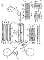
- Figur 1
- eine Doppelbandkaschiervorrichtung und
- Figuren 2-8
- verschiedene Ausführungsformen eines Zwei-Folien- Schichtverbunds.
- FIG. 1
- a Doppelbandkaschiervorrichtung and
- Figures 2-8
- various embodiments of a two-foil layer composite.
Die Abzugsgeschwindigkeit der Trägerfolien 1 und 2 von den Vorratsrollen 3 und 4 wird zunächst durch die Transportgeschwindigkeit der Doppelbandpresse 5 bestimmt. Gemäß einer ersten Ausführungsform wird die Vorratsrolle 3 der ersten Trägerfolie 1 so gesteuert, d.h. gebremst oder angetrieben, dass sie unter einer definierten Zugspannung steht. Diese Zugspannung sollte während des gesamten Prozesses konstant sein. Aufgrund des enormen Gewichts solcher Vorratsrollen zu Beginn des Abwickelprozesses und des während des Abwickelprozesses ständig abnehmenden Gewichts kann es vorkommen, dass die Vorratsrolle 3 zunächst angetrieben und im weiteren Verlauf des Abwickelprozesses gegebenenfalls gebremst wird. Auch die zweite Trägerfolie 2 steht in ähnlicher Weise unter Zugspannung.The withdrawal speed of the
Um nun zu gewährleisten, dass die auf der ersten Trägerfolie 1 aufgebrachten Sicherheitsmerkmale mit den auf der zweiten Trägerfolie 2 aufgebrachten Sicherheitsmerkmalen registergenau zusammengeführt werden, ist jede Trägerfolie 1, 2 mit Registermarken ausgestattet, welche mittels Registermarkendetektoren 10 erfasst werden. Wird durch Auswertung der erfassten Registermarkenpositionen ermittelt, dass die Registermarken der ersten Trägerfolie 1 relativ zu den Registermarken der zweiten Trägerfolie 2 nicht mehr innerhalb eines noch akzeptablen Toleranzbereichs liegen, so wird erfindungsgemäß eine der beiden Trägerfolien 1, 2 gedehnt. Dazu bieten sich die drei folgenden Varianten an:
Beide Trägerfolien 1, 2 stehen normalerweise unter derselben Zugspannung, unter welcher sich die Trägerfolien nicht dehnen. Sobald mittels der Registermarkendetektoren 10 festgestellt wird, dass die Sicherheitsmerkmale auf einer der beiden Trägerfolien relativ zu den Sicherheitsmerkmalen auf der anderen der beiden Trägerfolien nachlaufen, wird diese andere der beiden Trägerfolien geringfügig gedehnt, bis die Sicherheitsmerkmale der beiden Trägerfolien wieder innerhalb eines vorgegebenen Toleranzbereichs zueinander positioniert sind. Das Dehnen erfolgt vorzugsweise durch kontrolliertes Bremsen derjenigen Vorratsrolle, von der die zu dehnende Trägerfolie abgezogen wird.- Alternativ dazu kann die
zweite Trägerfolie 2 kürzer ausgebildet sein als die erste Trägerfolie 1, so dass diezweite Folie 2 relativ zur ersten Trägerfolie 1 grundsätzlich gedehnt werden muss, um eine registergenaue Laminierung der beiden Trägerfolien zu gestatten. Der notwendige Grad der Dehnung wird wiederum anhand der Registermarkendetektoren 10 ermittelt. - Gemäß einer weiteren Alternative kann die erste Trägerfolie 1 unter einer solchen Zugspannung abgezogen werden, dass sie sich grundsätzlich um einen vorgegebenen Prozentsatz dehnt. Im Normalfall wird dann die
zweite Trägerfolie 2 mit derselben Dehnung von der Vorratsrolle 4 abgezogen. Wird nun wiederum anhand der Registermarkendetektoren 10 eine Abweichung von der Registerlage festgestellt, so wird die Vorratsrolle 4 je nach Abweichungsrichtung mehr oder weniger gebremst, um die Dehnung der zweiten Trägerfolie 2 entsprechend zu verstärken oder zu reduzieren.
- Both
carrier films 1, 2 are normally under the same tensile stress, under which the carrier films do not stretch. As soon as it is determined by means of theregister mark detectors 10 that the security features on one of the two carrier films run on relative to the security features on the other of the two carrier films, this other of the two carrier films is slightly stretched until the security features of the two carrier films are again positioned within a predetermined tolerance range are. The stretching is preferably carried out by controlled braking of that supply roll from which the carrier film to be stretched is pulled off. - Alternatively, the
second carrier film 2 may be formed shorter than the first carrier film 1, so that thesecond film 2 must be stretched in principle relative to the first carrier film 1 in order to allow register-accurate lamination of the two carrier films. The necessary degree of elongation is again determined on the basis of theregister mark detectors 10. - According to a further alternative, the first carrier foil 1 can be pulled off under such a tensile stress that it basically stretches by a predetermined percentage. In the normal case, the
second carrier film 2 is then removed from the supply roll 4 with the same elongation. Will now turn on the basis of the register mark detectors If a deviation from the register position is detected, the supply roll 4 is braked more or less, depending on the direction of deviation, in order to correspondingly increase or reduce the elongation of thesecond carrier foil 2.
Die Trägerfolien 1, 2 können die Breite des später daraus zu fertigenden Sicherheitselements besitzen, beispielsweise die Breite eines Sicherheitsfadens oder -streifens für Banknoten. Vorzugsweise besitzen sie aber ein Vielfaches der Breite und die daraus zu fertigenden Sicherheitselemente werden anschließend aus dem laminierten Folienverbund herausgeteilt, indem der Folienverbund beispielsweise in Fäden oder Streifen geschnitten wird oder indem einzelne Sicherheitselemente aus dem Folienverbund, beispielsweise durch Ausstanzen in Etikettenform, herausgetrennt werden.The carrier foils 1, 2 may have the width of the security element to be subsequently produced therefrom, for example the width of a security thread or strip for banknotes. Preferably, however, they have a multiple of the width and the security elements to be produced therefrom are subsequently divided out of the laminated film composite by cutting the film composite into threads or strips or by separating individual security elements from the film composite, for example by punching in label form.
Im Falle von breiten Trägerfolien bietet es sich an, die Registermarken jeweils an den beiden äußersten Folienrändern zu platzieren, die dann bei der Weiterverarbeitung des Folienverbunds als Abfall anfallen werden. Alternativ dazu können die auf den Trägerfolien vorliegenden Sicherheitsmerkmale selbst als Registermarken dienen.In the case of wide carrier films, it is advisable to place the register marks on the two outermost film edges, which will then be produced as waste in the further processing of the film composite. Alternatively, the security features present on the carrier films may themselves serve as register marks.
Zur berührungslosen Detektierung der Registermarken im Auflicht oder im Durchlicht eignen sich insbesondere Lichtleiter oder CCD-Kameras.For contactless detection of the register marks in incident or transmitted light, in particular light guides or CCD cameras are suitable.
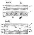
Bei der in
Es versteht sich, dass auch mehr als zwei Trägerfolien miteinander laminiert werden können, indem die in
Der Ausschnitt B der zweiten Trägerfolie 2 umfasst ebenfalls eine Trägerfolie 200 aus transparentem Kunststoff und wiederum eine aufgedampfte Metallschicht 201. Die Metallschicht 201 weist in üblicher Weise erzeugte Aussparungen in Form einer Negativschrift 202 auf. Die Breite der zweiten Tägerfolie 2 entspricht der Breite der ersten Trägerfolie 1. Die Negativschrift 202 ist in der Metallschicht 201 an derselben Stelle platziert, an der die Trägerfolie 100 der ersten Folie 1 den transparenten Bereich 103 besitzt. Die zweite Trägerfolie 2 ist im Bereich der Negativschrift 202 ihrerseits transparent. Dadurch bleibt der Sicherheitsfaden auch nach der Laminierung der Trägerfolien 1, 2 im Bereich der Negativschrift 202 transparent.The cutout B of the
Der Ausschnitt C in
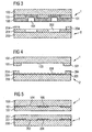
Das in
Die
Zusätzlich ist bei der Ausführungsform gemäß
Die Beugungsstrukturen 206 müssen nicht notwendigerweise in die Trägerfolie 200 eingeprägt sein. Es ist genauso möglich, ein die Beugungsstrukturen aufweisendes Transferelement registergenau auf die Trägerfolie 200 zu applizieren. Stattdessen können aber auch bei dieser Ausführungsvariante andere optisch variable Sicherheitsmerkmale vorgesehen werden, wie beispielsweise Dünnschichtaufbauten und dergleichen.The
Das Sicherheitselement gemäß
Zusätzlich besitzen die Farbschichten 110, 210 bei dem Ausführungsbeispiel nach
Claims (10)
- A method for producing a layer compound (6) with at least two security features disposed in register to each other, comprising the following steps:- providing a first carrier foil (100) with at least one first security feature and first register marks,- providing a second carrier foil (200) with at least one second security feature and second register marks,- connecting the first carrier foil with the second carrier foil, at least one of the two carrier foils being held under tensile stress and the second or, optionally, the first carrier foil being controlled in longitudinal direction and transverse direction of the carrier foil with the help of the first and second register marks in such a way that a layer compound is the result in which the first and second security features are disposed in register to each other, the controlling of the second carrier foil (200) or, optionally, the first carrier foil (100) being effected by stretching the carrier foil in longitudinal direction of the carrier foil.
- The method according to claim 1, characterized in that the second carrier foil (200) is shorter than the first carrier foil (100) and is stretched relative to the first carrier foil (100).
- The method according to claim 1, characterized in that the first carrier foil (100) due to the tensile stress is constantly stretched in longitudinal direction of the carrier foil and the second carrier foil (200) is stretched relative to the stretching of the first carrier foil (100).
- The method according to one of the claims 1 to 3, characterized in that the carrier foils (100, 200) are provided on rollers (3, 4) and are drawn off the rollers, and wherein the stretching of the first and/ or second carrier foil (100 or 200) in longitudinal direction of the carrier foil is achieved by a controlled slowing down of this roller when drawing off the carrier foil from the respective roller.
- The method according to one of the claims 1 to 4, characterized in that an exactly registered connection of the two carrier foils (100, 200) with respect to their longitudinal edges is achieved by means of a tensioning group (11).
- The method according to claim 5, characterized in that the tensioning group is controlled with the help of the first and second register marks.
- The method according to one of the claims 1 to 6, characterized in that the register marks are read by means of light guides or CCD-cameras.
- The method according to one of the claims 1 to 7, characterized in that the security features are used as register marks.
- The method according to one of the claims 1 to 8, characterized in that the layer compound is divided into so-called endless threads or endless bands.
- The method for producing a security element comprising the procedure steps according to one of the claims 1 to 7, characterized in that from the layer compound (6) a security element with its final transverse and longitudinal dimensions is divided out.
Applications Claiming Priority (3)
| Application Number | Priority Date | Filing Date | Title |
|---|---|---|---|
| DE10226177A DE10226177A1 (en) | 2002-06-12 | 2002-06-12 | Layered composite for security element |
| DE10226177 | 2002-06-12 | ||
| PCT/EP2003/005981 WO2003106185A2 (en) | 2002-06-12 | 2003-06-06 | Interlaminar structure for security element |
Publications (2)
| Publication Number | Publication Date |
|---|---|
| EP1515857A2 EP1515857A2 (en) | 2005-03-23 |
| EP1515857B1 true EP1515857B1 (en) | 2009-04-01 |
Family
ID=29594445
Family Applications (1)
| Application Number | Title | Priority Date | Filing Date |
|---|---|---|---|
| EP03759917A Expired - Lifetime EP1515857B1 (en) | 2002-06-12 | 2003-06-06 | Interlaminar structure for security element |
Country Status (7)
| Country | Link |
|---|---|
| US (1) | US7744797B2 (en) |
| EP (1) | EP1515857B1 (en) |
| AT (1) | ATE427222T1 (en) |
| AU (1) | AU2003242644A1 (en) |
| DE (2) | DE10226177A1 (en) |
| RU (1) | RU2331523C2 (en) |
| WO (1) | WO2003106185A2 (en) |
Families Citing this family (14)
| Publication number | Priority date | Publication date | Assignee | Title |
|---|---|---|---|---|
| DE10226177A1 (en) | 2002-06-12 | 2003-12-24 | Giesecke & Devrient Gmbh | Layered composite for security element |
| DE10255639A1 (en) * | 2002-11-28 | 2004-06-17 | Giesecke & Devrient Gmbh | Security element and method of manufacturing the same |
| GB2457185B (en) | 2006-05-13 | 2009-09-23 | Filtrona United Kingdom Ltd | Security laminates and documents |
| DE102006023866A1 (en) | 2006-05-19 | 2007-11-22 | Giesecke & Devrient Gmbh | security element |
| ITMI20080053A1 (en) | 2008-01-15 | 2009-07-16 | Fabriano Securities Srl | SECURITY ELEMENT, PARTICULARLY FOR BANKNOTES, SECURITY CARDS AND THE LIKE, WITH AN ANTI-COUNTERFEIT CHARACTERISTICS. |
| DE102008030409A1 (en) † | 2008-06-27 | 2009-12-31 | Giesecke & Devrient Gmbh | Safety element with recess and method for producing the same |
| WO2010052513A1 (en) * | 2008-10-27 | 2010-05-14 | Luiten, Marco | Method for applying a strip-shaped element, in particular a security thread, to a ribbon-like substrate and device for carrying out the method, and use thereof |
| DE102010009976A1 (en) * | 2010-03-03 | 2011-09-08 | Giesecke & Devrient Gmbh | Value document with register-accurately positioned security element |
| JP5915577B2 (en) * | 2012-04-18 | 2016-05-11 | コニカミノルタ株式会社 | Foil transfer device and image forming system |
| JP5915578B2 (en) * | 2012-05-17 | 2016-05-11 | コニカミノルタ株式会社 | Image forming system |
| US9081332B2 (en) * | 2012-05-17 | 2015-07-14 | Konica Minolta, Inc. | Image forming system for transferring a foil image |
| GB2516829B (en) * | 2013-07-29 | 2017-03-01 | De La Rue Int Ltd | Improvements in security elements |
| US10147030B2 (en) * | 2016-09-08 | 2018-12-04 | Capital One Services, Llc | Transaction card having internal magnetic stripe |
| RU178207U1 (en) * | 2017-02-27 | 2018-03-26 | Алексей Алексеевич Гришаков | Label to protect product packaging from counterfeiting and attract customer attention |
Family Cites Families (18)
| Publication number | Priority date | Publication date | Assignee | Title |
|---|---|---|---|---|
| US3601913A (en) | 1968-07-22 | 1971-08-31 | Fmc Corp | Magnetic transaction card and method in forming the same |
| US3949949A (en) | 1975-04-25 | 1976-04-13 | Phillips Petroleum Company | Web tension control |
| DE2653196C3 (en) | 1976-11-23 | 1980-05-29 | I M A Industria Macchine Automatiche S.P.A., Ozzano Emilia, Bologna (Italien) | Device for centering the labels on packaging |
| DE3039616A1 (en) | 1980-10-21 | 1982-05-19 | Robert Bosch Gmbh, 7000 Stuttgart | METHOD AND DEVICE FOR MERGING TWO CONTINUOUSLY MOVING FILM LINES INTO THE REGISTER |
| DE3042709A1 (en) | 1980-11-13 | 1982-06-24 | Robert Bosch Gmbh, 7000 Stuttgart | Guide for thermoplastics wrapping in packaging machine - has cover track guided in loop above lower track which includes article receptacles |
| US4536016A (en) | 1981-08-24 | 1985-08-20 | Solomon David H | Banknotes and the like |
| DE3872005T2 (en) | 1987-03-20 | 1992-12-03 | Kubota Med Appliance Supply | CENTRIFUGAL SEPARATOR. |
| GB8912750D0 (en) * | 1989-06-02 | 1989-07-19 | Portals Ltd | Security paper |
| US5509691A (en) * | 1992-10-26 | 1996-04-23 | Gao Gesellschaft Fur Automation Und Organisation Mbh | Security element in the form of threads or strips to be embedded in security documents and a method for producing and testing the same |
| KR100362350B1 (en) | 1994-03-16 | 2003-02-19 | 오브이디 키네그람 악티엔게젤샤프트 | Optical carrier with optical label |
| US5964970A (en) | 1997-10-14 | 1999-10-12 | Kimberly-Clark Worldwide, Inc. | Registration process and apparatus for continuously moving elasticized layers having multiple components |
| DE19746823C1 (en) | 1997-10-23 | 1999-04-08 | Goedecke Ag | Uniaxial stretching machine for e.g. printed aluminum foil covering pharmaceutical blister pack |
| DE19804735B4 (en) | 1998-02-06 | 2006-06-29 | Windmöller & Hölscher Kg | Method and device for aligning two webs brought together into a multilayer web |
| AU6257400A (en) | 1999-08-06 | 2001-03-05 | Fofitec Ag | Form with detachable or removable card, and device and method for dispensing parts of a material to be dispensed on a moving printing carrier |
| AT412273B (en) | 2001-12-07 | 2004-12-27 | Hueck Folien Gmbh | METHOD FOR PRODUCING MULTILAYER STRUCTURES PRINTED TO REGISTER, PRODUCTS PRODUCED BY THIS METHOD AND THE USE THEREOF |
| JP2005512860A (en) * | 2001-12-21 | 2005-05-12 | ギーゼッケ ウント デフリエント ゲーエムベーハー | Security element and method for producing the same |
| DE10226177A1 (en) | 2002-06-12 | 2003-12-24 | Giesecke & Devrient Gmbh | Layered composite for security element |
| US6949949B2 (en) * | 2002-12-17 | 2005-09-27 | Ip-First, Llc | Apparatus and method for adjusting the impedance of an output driver |
-
2002
- 2002-06-12 DE DE10226177A patent/DE10226177A1/en not_active Withdrawn
-
2003
- 2003-06-06 US US10/517,492 patent/US7744797B2/en not_active Expired - Fee Related
- 2003-06-06 EP EP03759917A patent/EP1515857B1/en not_active Expired - Lifetime
- 2003-06-06 AT AT03759917T patent/ATE427222T1/en active
- 2003-06-06 AU AU2003242644A patent/AU2003242644A1/en not_active Abandoned
- 2003-06-06 WO PCT/EP2003/005981 patent/WO2003106185A2/en not_active Application Discontinuation
- 2003-06-06 DE DE50311372T patent/DE50311372D1/en not_active Expired - Lifetime
- 2003-06-06 RU RU2005100759/11A patent/RU2331523C2/en not_active IP Right Cessation
Also Published As
| Publication number | Publication date |
|---|---|
| EP1515857A2 (en) | 2005-03-23 |
| DE10226177A1 (en) | 2003-12-24 |
| RU2331523C2 (en) | 2008-08-20 |
| RU2005100759A (en) | 2006-06-10 |
| US20060145467A1 (en) | 2006-07-06 |
| AU2003242644A1 (en) | 2003-12-31 |
| WO2003106185A3 (en) | 2004-06-03 |
| WO2003106185A2 (en) | 2003-12-24 |
| AU2003242644A8 (en) | 2003-12-31 |
| US7744797B2 (en) | 2010-06-29 |
| DE50311372D1 (en) | 2009-05-14 |
| ATE427222T1 (en) | 2009-04-15 |
Similar Documents
| Publication | Publication Date | Title |
|---|---|---|
| EP1156927B1 (en) | Method for producing multi-layer security products and a security product produced according to this method | |
| EP1458575B2 (en) | Security element for security papers and valuable documents | |
| EP3287296B1 (en) | Method and device for hot stamping | |
| EP1682723B1 (en) | Security element with a color-shift effect | |
| EP1515857B1 (en) | Interlaminar structure for security element | |
| DE4334847A1 (en) | Value document with window | |
| DE4334848C1 (en) | Security with window | |
| EP2480417A1 (en) | Elongated security feature comprising machine-readable magnetic regions | |
| EP3505361B1 (en) | Application device | |
| EP3548299B1 (en) | Value document | |
| DE10222433A1 (en) | Strip-shaped security element | |
| EP3268235B1 (en) | Method for producing a value-document substrate, value-document substrate that can be obtained therefrom, and value document | |
| EP2753754B2 (en) | Method for producing a security paper and microlens thread | |
| DE102008053096A1 (en) | Method and device for the production of data carriers and semi-finished media, as well as data carriers and semi-finished media | |
| EP2448766B1 (en) | Security element, and method for the production thereof | |
| EP3828640A1 (en) | Method for the preparation of security documents | |
| EP1273705B1 (en) | Method and apparatus for preparing a substrate with security elements for security documents | |
| EP2718112B1 (en) | Sheet document with a translucent or transparent region | |
| DE102008019871B3 (en) | Method for the production of multilayered security document, comprises subjecting a photopolymer foil on a first side of a carrier material and connecting the foil with the carrier material | |
| EP3580066B1 (en) | Data carrier with a window security element | |
| EP4219185A1 (en) | Film, film strip, valuable document and relative production method | |
| DE10134817A1 (en) | Production of a plastic film used in the production of e.g. ID cards comprises bending strips from a plastic film, threading a security thread between the film and the strips, integrating by moving the strips back into the film plane | |
| EP2965918B1 (en) | Data carrier with tactile relief structure | |
| DE102022000589A1 (en) | Device for transferring a security element onto a target substrate | |
| EP1506853A2 (en) | Method for producing a security film |
Legal Events
| Date | Code | Title | Description |
|---|---|---|---|
| PUAI | Public reference made under article 153(3) epc to a published international application that has entered the european phase |
Free format text: ORIGINAL CODE: 0009012 |
|
| 17P | Request for examination filed |
Effective date: 20050112 |
|
| AK | Designated contracting states |
Kind code of ref document: A2 Designated state(s): AT BE BG CH CY CZ DE DK EE ES FI FR GB GR HU IE IT LI LU MC NL PT RO SE SI SK TR |
|
| AX | Request for extension of the european patent |
Extension state: AL LT LV MK |
|
| DAX | Request for extension of the european patent (deleted) | ||
| GRAP | Despatch of communication of intention to grant a patent |
Free format text: ORIGINAL CODE: EPIDOSNIGR1 |
|
| GRAS | Grant fee paid |
Free format text: ORIGINAL CODE: EPIDOSNIGR3 |
|
| GRAA | (expected) grant |
Free format text: ORIGINAL CODE: 0009210 |
|
| AK | Designated contracting states |
Kind code of ref document: B1 Designated state(s): AT BE BG CH CY CZ DE DK EE ES FI FR GB GR HU IE IT LI LU MC NL PT RO SE SI SK TR |
|
| REG | Reference to a national code |
Ref country code: GB Ref legal event code: FG4D Free format text: NOT ENGLISH |
|
| REG | Reference to a national code |
Ref country code: CH Ref legal event code: EP |
|
| REG | Reference to a national code |
Ref country code: IE Ref legal event code: FG4D Free format text: LANGUAGE OF EP DOCUMENT: GERMAN |
|
| REF | Corresponds to: |
Ref document number: 50311372 Country of ref document: DE Date of ref document: 20090514 Kind code of ref document: P |
|
| REG | Reference to a national code |
Ref country code: SE Ref legal event code: TRGR |
|
| PG25 | Lapsed in a contracting state [announced via postgrant information from national office to epo] |
Ref country code: SI Free format text: LAPSE BECAUSE OF FAILURE TO SUBMIT A TRANSLATION OF THE DESCRIPTION OR TO PAY THE FEE WITHIN THE PRESCRIBED TIME-LIMIT Effective date: 20090401 |
|
| REG | Reference to a national code |
Ref country code: IE Ref legal event code: FD4D |
|
| PG25 | Lapsed in a contracting state [announced via postgrant information from national office to epo] |
Ref country code: EE Free format text: LAPSE BECAUSE OF FAILURE TO SUBMIT A TRANSLATION OF THE DESCRIPTION OR TO PAY THE FEE WITHIN THE PRESCRIBED TIME-LIMIT Effective date: 20090401 Ref country code: ES Free format text: LAPSE BECAUSE OF FAILURE TO SUBMIT A TRANSLATION OF THE DESCRIPTION OR TO PAY THE FEE WITHIN THE PRESCRIBED TIME-LIMIT Effective date: 20090712 Ref country code: FI Free format text: LAPSE BECAUSE OF FAILURE TO SUBMIT A TRANSLATION OF THE DESCRIPTION OR TO PAY THE FEE WITHIN THE PRESCRIBED TIME-LIMIT Effective date: 20090401 Ref country code: PT Free format text: LAPSE BECAUSE OF FAILURE TO SUBMIT A TRANSLATION OF THE DESCRIPTION OR TO PAY THE FEE WITHIN THE PRESCRIBED TIME-LIMIT Effective date: 20090902 |
|
| BERE | Be: lapsed |
Owner name: GIESECKE & DEVRIENT G.M.B.H. Effective date: 20090630 |
|
| PLBI | Opposition filed |
Free format text: ORIGINAL CODE: 0009260 |
|
| PLBI | Opposition filed |
Free format text: ORIGINAL CODE: 0009260 |
|
| PG25 | Lapsed in a contracting state [announced via postgrant information from national office to epo] |
Ref country code: RO Free format text: LAPSE BECAUSE OF FAILURE TO SUBMIT A TRANSLATION OF THE DESCRIPTION OR TO PAY THE FEE WITHIN THE PRESCRIBED TIME-LIMIT Effective date: 20090401 Ref country code: CZ Free format text: LAPSE BECAUSE OF FAILURE TO SUBMIT A TRANSLATION OF THE DESCRIPTION OR TO PAY THE FEE WITHIN THE PRESCRIBED TIME-LIMIT Effective date: 20090401 Ref country code: MC Free format text: LAPSE BECAUSE OF NON-PAYMENT OF DUE FEES Effective date: 20090630 Ref country code: IE Free format text: LAPSE BECAUSE OF FAILURE TO SUBMIT A TRANSLATION OF THE DESCRIPTION OR TO PAY THE FEE WITHIN THE PRESCRIBED TIME-LIMIT Effective date: 20090401 Ref country code: DK Free format text: LAPSE BECAUSE OF FAILURE TO SUBMIT A TRANSLATION OF THE DESCRIPTION OR TO PAY THE FEE WITHIN THE PRESCRIBED TIME-LIMIT Effective date: 20090401 |
|
| REG | Reference to a national code |
Ref country code: CH Ref legal event code: PL |
|
| 26 | Opposition filed |
Opponent name: FABRIANO SECURITIES S.R.L. Effective date: 20091223 |
|
| 26 | Opposition filed |
Opponent name: HUECK FOLIEN GMBH Effective date: 20091231 Opponent name: FABRIANO SECURITIES S.R.L. Effective date: 20091223 |
|
| PG25 | Lapsed in a contracting state [announced via postgrant information from national office to epo] |
Ref country code: SK Free format text: LAPSE BECAUSE OF FAILURE TO SUBMIT A TRANSLATION OF THE DESCRIPTION OR TO PAY THE FEE WITHIN THE PRESCRIBED TIME-LIMIT Effective date: 20090401 |
|
| PLAX | Notice of opposition and request to file observation + time limit sent |
Free format text: ORIGINAL CODE: EPIDOSNOBS2 |
|
| PG25 | Lapsed in a contracting state [announced via postgrant information from national office to epo] |
Ref country code: BG Free format text: LAPSE BECAUSE OF FAILURE TO SUBMIT A TRANSLATION OF THE DESCRIPTION OR TO PAY THE FEE WITHIN THE PRESCRIBED TIME-LIMIT Effective date: 20090701 |
|
| NLR1 | Nl: opposition has been filed with the epo |
Opponent name: HUECK FOLIEN GMBH Opponent name: FABRIANO SECURITIES S.R.L. |
|
| PG25 | Lapsed in a contracting state [announced via postgrant information from national office to epo] |
Ref country code: CH Free format text: LAPSE BECAUSE OF NON-PAYMENT OF DUE FEES Effective date: 20090630 Ref country code: LI Free format text: LAPSE BECAUSE OF NON-PAYMENT OF DUE FEES Effective date: 20090630 |
|
| PLAF | Information modified related to communication of a notice of opposition and request to file observations + time limit |
Free format text: ORIGINAL CODE: EPIDOSCOBS2 |
|
| PG25 | Lapsed in a contracting state [announced via postgrant information from national office to epo] |
Ref country code: BE Free format text: LAPSE BECAUSE OF NON-PAYMENT OF DUE FEES Effective date: 20090630 |
|
| PLBB | Reply of patent proprietor to notice(s) of opposition received |
Free format text: ORIGINAL CODE: EPIDOSNOBS3 |
|
| PLAY | Examination report in opposition despatched + time limit |
Free format text: ORIGINAL CODE: EPIDOSNORE2 |
|
| PG25 | Lapsed in a contracting state [announced via postgrant information from national office to epo] |
Ref country code: GR Free format text: LAPSE BECAUSE OF FAILURE TO SUBMIT A TRANSLATION OF THE DESCRIPTION OR TO PAY THE FEE WITHIN THE PRESCRIBED TIME-LIMIT Effective date: 20090702 |
|
| PLAH | Information related to despatch of examination report in opposition + time limit modified |
Free format text: ORIGINAL CODE: EPIDOSCORE2 |
|
| PG25 | Lapsed in a contracting state [announced via postgrant information from national office to epo] |
Ref country code: LU Free format text: LAPSE BECAUSE OF NON-PAYMENT OF DUE FEES Effective date: 20090606 |
|
| PLBC | Reply to examination report in opposition received |
Free format text: ORIGINAL CODE: EPIDOSNORE3 |
|
| PG25 | Lapsed in a contracting state [announced via postgrant information from national office to epo] |
Ref country code: HU Free format text: LAPSE BECAUSE OF FAILURE TO SUBMIT A TRANSLATION OF THE DESCRIPTION OR TO PAY THE FEE WITHIN THE PRESCRIBED TIME-LIMIT Effective date: 20091002 |
|
| PG25 | Lapsed in a contracting state [announced via postgrant information from national office to epo] |
Ref country code: TR Free format text: LAPSE BECAUSE OF FAILURE TO SUBMIT A TRANSLATION OF THE DESCRIPTION OR TO PAY THE FEE WITHIN THE PRESCRIBED TIME-LIMIT Effective date: 20090401 |
|
| PG25 | Lapsed in a contracting state [announced via postgrant information from national office to epo] |
Ref country code: CY Free format text: LAPSE BECAUSE OF FAILURE TO SUBMIT A TRANSLATION OF THE DESCRIPTION OR TO PAY THE FEE WITHIN THE PRESCRIBED TIME-LIMIT Effective date: 20090401 |
|
| RDAF | Communication despatched that patent is revoked |
Free format text: ORIGINAL CODE: EPIDOSNREV1 |
|
| APBM | Appeal reference recorded |
Free format text: ORIGINAL CODE: EPIDOSNREFNO |
|
| APBP | Date of receipt of notice of appeal recorded |
Free format text: ORIGINAL CODE: EPIDOSNNOA2O |
|
| APAH | Appeal reference modified |
Free format text: ORIGINAL CODE: EPIDOSCREFNO |
|
| APBQ | Date of receipt of statement of grounds of appeal recorded |
Free format text: ORIGINAL CODE: EPIDOSNNOA3O |
|
| PLAB | Opposition data, opponent's data or that of the opponent's representative modified |
Free format text: ORIGINAL CODE: 0009299OPPO |
|
| R26 | Opposition filed (corrected) |
Opponent name: FEDRIGONI S.P.A. Effective date: 20091223 |
|
| REG | Reference to a national code |
Ref country code: DE Ref legal event code: R082 Ref document number: 50311372 Country of ref document: DE |
|
| APBU | Appeal procedure closed |
Free format text: ORIGINAL CODE: EPIDOSNNOA9O |
|
| REG | Reference to a national code |
Ref country code: FR Ref legal event code: PLFP Year of fee payment: 14 |
|
| PLCK | Communication despatched that opposition was rejected |
Free format text: ORIGINAL CODE: EPIDOSNREJ1 |
|
| APBM | Appeal reference recorded |
Free format text: ORIGINAL CODE: EPIDOSNREFNO |
|
| APBP | Date of receipt of notice of appeal recorded |
Free format text: ORIGINAL CODE: EPIDOSNNOA2O |
|
| APAH | Appeal reference modified |
Free format text: ORIGINAL CODE: EPIDOSCREFNO |
|
| REG | Reference to a national code |
Ref country code: FR Ref legal event code: PLFP Year of fee payment: 15 |
|
| APBQ | Date of receipt of statement of grounds of appeal recorded |
Free format text: ORIGINAL CODE: EPIDOSNNOA3O |
|
| PLAB | Opposition data, opponent's data or that of the opponent's representative modified |
Free format text: ORIGINAL CODE: 0009299OPPO |
|
| R26 | Opposition filed (corrected) |
Opponent name: HUECK FOLIEN GMBH Effective date: 20091231 |
|
| REG | Reference to a national code |
Ref country code: DE Ref legal event code: R081 Ref document number: 50311372 Country of ref document: DE Owner name: GIESECKE+DEVRIENT CURRENCY TECHNOLOGY GMBH, DE Free format text: FORMER OWNER: GIESECKE & DEVRIENT GMBH, 81677 MUENCHEN, DE |
|
| REG | Reference to a national code |
Ref country code: NL Ref legal event code: PD Owner name: GIESECKE+DEVRIENT CURRENCY TECHNOLOGY GMBH; DE Free format text: DETAILS ASSIGNMENT: CHANGE OF OWNER(S), ASSIGNMENT; FORMER OWNER NAME: GIESECKE & DEVRIENT GMBH Effective date: 20171205 |
|
| REG | Reference to a national code |
Ref country code: GB Ref legal event code: 732E Free format text: REGISTERED BETWEEN 20180118 AND 20180124 |
|
| RAP2 | Party data changed (patent owner data changed or rights of a patent transferred) |
Owner name: GIESECKE+DEVRIENT CURRENCY TECHNOLOGY GMBH |
|
| REG | Reference to a national code |
Ref country code: AT Ref legal event code: PC Ref document number: 427222 Country of ref document: AT Kind code of ref document: T Owner name: GIESECKE+DEVRIENT CURRENCY TECHNOLOGY GMBH, DE Effective date: 20180425 |
|
| REG | Reference to a national code |
Ref country code: FR Ref legal event code: PLFP Year of fee payment: 16 |
|
| REG | Reference to a national code |
Ref country code: FR Ref legal event code: TP Owner name: GIESECKE+DEVRIENT CURRENCY TECHNOLOGY GMBH, DE Effective date: 20180530 |
|
| REG | Reference to a national code |
Ref country code: NL Ref legal event code: MM Effective date: 20180701 |
|
| PG25 | Lapsed in a contracting state [announced via postgrant information from national office to epo] |
Ref country code: NL Free format text: LAPSE BECAUSE OF NON-PAYMENT OF DUE FEES Effective date: 20180701 |
|
| REG | Reference to a national code |
Ref country code: DE Ref legal event code: R100 Ref document number: 50311372 Country of ref document: DE |
|
| PGFP | Annual fee paid to national office [announced via postgrant information from national office to epo] |
Ref country code: SE Payment date: 20190624 Year of fee payment: 17 |
|
| APBU | Appeal procedure closed |
Free format text: ORIGINAL CODE: EPIDOSNNOA9O |
|
| APAN | Information on closure of appeal procedure modified |
Free format text: ORIGINAL CODE: EPIDOSCNOA9O |
|
| PLBN | Opposition rejected |
Free format text: ORIGINAL CODE: 0009273 |
|
| STAA | Information on the status of an ep patent application or granted ep patent |
Free format text: STATUS: OPPOSITION REJECTED |
|
| 27O | Opposition rejected |
Effective date: 20190704 |
|
| PG25 | Lapsed in a contracting state [announced via postgrant information from national office to epo] |
Ref country code: SE Free format text: LAPSE BECAUSE OF NON-PAYMENT OF DUE FEES Effective date: 20200607 |
|
| PGFP | Annual fee paid to national office [announced via postgrant information from national office to epo] |
Ref country code: FR Payment date: 20210621 Year of fee payment: 19 Ref country code: DE Payment date: 20210630 Year of fee payment: 19 Ref country code: IT Payment date: 20210630 Year of fee payment: 19 |
|
| PGFP | Annual fee paid to national office [announced via postgrant information from national office to epo] |
Ref country code: AT Payment date: 20210618 Year of fee payment: 19 Ref country code: GB Payment date: 20210623 Year of fee payment: 19 |
|
| REG | Reference to a national code |
Ref country code: SE Ref legal event code: EUG |
|
| REG | Reference to a national code |
Ref country code: DE Ref legal event code: R119 Ref document number: 50311372 Country of ref document: DE |
|
| REG | Reference to a national code |
Ref country code: AT Ref legal event code: MM01 Ref document number: 427222 Country of ref document: AT Kind code of ref document: T Effective date: 20220606 |
|
| GBPC | Gb: european patent ceased through non-payment of renewal fee |
Effective date: 20220606 |
|
| PG25 | Lapsed in a contracting state [announced via postgrant information from national office to epo] |
Ref country code: FR Free format text: LAPSE BECAUSE OF NON-PAYMENT OF DUE FEES Effective date: 20220630 Ref country code: AT Free format text: LAPSE BECAUSE OF NON-PAYMENT OF DUE FEES Effective date: 20220606 |
|
| PG25 | Lapsed in a contracting state [announced via postgrant information from national office to epo] |
Ref country code: GB Free format text: LAPSE BECAUSE OF NON-PAYMENT OF DUE FEES Effective date: 20220606 Ref country code: DE Free format text: LAPSE BECAUSE OF NON-PAYMENT OF DUE FEES Effective date: 20230103 |
|
| PG25 | Lapsed in a contracting state [announced via postgrant information from national office to epo] |
Ref country code: IT Free format text: LAPSE BECAUSE OF NON-PAYMENT OF DUE FEES Effective date: 20220606 |