EP1515264A2 - Lokalisierungsmuster und Verfahren und Vorrichtung zur Erzeugung solcher Muster - Google Patents
Lokalisierungsmuster und Verfahren und Vorrichtung zur Erzeugung solcher Muster Download PDFInfo
- Publication number
- EP1515264A2 EP1515264A2 EP04104163A EP04104163A EP1515264A2 EP 1515264 A2 EP1515264 A2 EP 1515264A2 EP 04104163 A EP04104163 A EP 04104163A EP 04104163 A EP04104163 A EP 04104163A EP 1515264 A2 EP1515264 A2 EP 1515264A2
- Authority
- EP
- European Patent Office
- Prior art keywords
- dots
- pattern
- printer
- dot
- shape
- Prior art date
- Legal status (The legal status is an assumption and is not a legal conclusion. Google has not performed a legal analysis and makes no representation as to the accuracy of the status listed.)
- Withdrawn
Links
Images


Classifications
-
- G—PHYSICS
- G06—COMPUTING OR CALCULATING; COUNTING
- G06K—GRAPHICAL DATA READING; PRESENTATION OF DATA; RECORD CARRIERS; HANDLING RECORD CARRIERS
- G06K1/00—Methods or arrangements for marking the record carrier in digital fashion
- G06K1/12—Methods or arrangements for marking the record carrier in digital fashion otherwise than by punching
- G06K1/121—Methods or arrangements for marking the record carrier in digital fashion otherwise than by punching by printing code marks
-
- G—PHYSICS
- G06—COMPUTING OR CALCULATING; COUNTING
- G06K—GRAPHICAL DATA READING; PRESENTATION OF DATA; RECORD CARRIERS; HANDLING RECORD CARRIERS
- G06K15/00—Arrangements for producing a permanent visual presentation of the output data, e.g. computer output printers
- G06K15/02—Arrangements for producing a permanent visual presentation of the output data, e.g. computer output printers using printers
-
- G—PHYSICS
- G06—COMPUTING OR CALCULATING; COUNTING
- G06K—GRAPHICAL DATA READING; PRESENTATION OF DATA; RECORD CARRIERS; HANDLING RECORD CARRIERS
- G06K2215/00—Arrangements for producing a permanent visual presentation of the output data
- G06K2215/0082—Architecture adapted for a particular function
Definitions
- This invention relates to location patterns, typically printed on a document and typically used to allow the position of a device such as a pen to be determined relative to the pattern, and to methods and apparatus for generating such patterns.
- the invention arose out of a consideration of the work of AnotoTM Group AB and others in relation to digital pattern paper and digital pens. It is convenient to discuss the invention in that contextual background, but it will be appreciated that the invention is not restricted to use with any proprietary system.
- Figure 1a shows schematically part of an A4 sheet 10 of Anoto digital paper.
- the sheet 10 has printed on it a part of a very large non-repeating pattern 12 of dots 14.
- the dots 14 of the pattern 12 are printed using infra-red absorbing black ink.
- the dots give the sheet 12 a pale grey appearance.
- An enlarged view of a small area of the pattern 12 is illustrated in Figure 1b.
- the position identifying pattern 12 is made up of a number of dots 14 arranged on an imaginary square grid 16.
- the grid 16 can be considered as being made up of horizontal and vertical lines 16a, 16b defining a number of grid squares of side length 300 ⁇ m, together with a number of intersections 16c where horizontal and vertical lines cross.
- One dot 14 is provided at each intersection 16c, but offset slightly in one of four possible directions up, down, left or right, from the actual intersection 16c.
- the dot offsets are arranged to vary in a systematic way so that the pattern formed by any group of a sufficient number of dots, for example a group of 36 dots arranged in a six by six square, will be unique within a very large area of the pattern.
- An example of this type of pattern is described in WO 01 /26033.
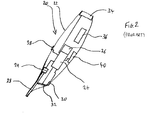
- FIG. 2 schematically shows a digital pen 20 adapted to write human readable ink in non-machine-readable IR transparent ink and to read a position dot pattern in infra-red.
- the pen 20 has a housing 22, a processor 24 with access to memory 26, a removable and replaceable ink nib and cartridge unit 28, a pressure sensor 29 adapted to be able to identify when the nib is pressed against a document, an infra-red LED emitter 30 adapted to emit infra-red light of a specified wavelength, an infra-red sensitive camera 32 (e.g. a CCD or CMOS sensor), a wireless telecommunications transceiver 34, and a removable and replaceable battery 36.
- an infra-red sensitive camera 32 e.g. a CCD or CMOS sensor
- a wireless telecommunications transceiver 34 e.g. a CCD or CMOS sensor
- a removable and replaceable battery 36 e.g. a CCD
- the pen 20 when in use writing or marking the page 10, images a 6x6 array of dots 14.
- the pen's processor 24 establishes its position in the dot pattern 12 from that image.
- the processor 24 processes data acquired by the camera 32 and the transceiver 34 communicates processed information from the processor 24 to a remote complementary transceiver (e.g. to a receiver linked to a PC).
- a remote complementary transceiver e.g. to a receiver linked to a PC.
- that information will include information related to where in the dot pattern the pen is, or has been, and its pattern of movement.
- One problem avoided by such a system is that of users who design their own forms or documents, printing human-discernable or readable content over the dot pattern with the wrong ink (ink that is IR-absorbing ink), thereby masking the dot pattern from the digital pen, when the pen is used.
- ink ink that is IR-absorbing ink
- the digital pattern 12 being printed with characteristics that are different to those required for it to be read by the pen 20.
- the relative positions and sizes of the elements of the pattern are controlled to be within pre-set tolerances.
- a pattern may be printed which conforms to the specifications of the system and which is suitable for use with the pen.
- elements of the pattern that are controlled to be within pre-set tolerances include: the spacing between adjacent parallel lines of the grid 16; the distance by which the dots 14 are offset from their corresponding grid intersections 16c; and, the diameter of the dots 14.
- a printer system comprising a printer adapted to print a location pattern comprising a plurality of dots, each having a substantially predetermined size and nominal position in the pattern, the printer having a resolution constraining the position at which the dots may be printed, the system being adapted to modify at least some of the dots prior to printing such that the modified dots have an optical centre of gravity that more closely coincides with their nominal positions.
- the present invention also extends to: software and a printer driver for generating such a location pattern; and, corresponding methods for generating or printing such location patterns; as defined in the appended claims.
- Figure 3 is a schematic illustration of a system 50 for printing a document having a pattern, according to an embodiment of the invention.
- the system 50 comprises a workstation 51 including a personal computer (PC) 52 which is connected to a local printer 60.
- the printer may instead be connected to the PC 52 via a network.
- the PC 52 may also be connected to the Internet 62.
- the PC 52 includes a user interface including a screen 58, a keyboard 54 and a mouse 56.
- the PC 52 has as a processor 52a, a memory 52b, and I/O software devices 52c by means of which the processor communicates with the screen 58, the keyboard 54 and the mouse 56 and a communications port 57 by means of which it communicates with the Internet 62 or a local network such as a LAN 59 having peripheral devices and/or other computers (e.g. PCs) 59a.
- the workstation 51 has access to a database 52d of pattern data for use with Anoto-type digital documents.
- the database 52d may also have user names and identification numbers, which are in use associated with each particular document at the time of printing of the document and which may be printed out with the document.
- This database 52d may be on the PC or elsewhere on a network, for example on a local file server or on the Internet. This may take the form of a digital pattern space allocation server as is used in the Anoto system.
- the PC 52 also includes a software tool, known as a Print-on-Demand (PoD) tool, referenced 52e the figure.
- the PoD tool 52e has access to the database 52d of pattern data, as is described in more detail below.
- the PC 52 is arranged to generate electronic digital documents that comprise a pattern 12 of dots 14.
- the digital documents may be "Anoto-type" digital documents. However, it will be appreciated that the invention is not restricted to use with any proprietary system.
- the digital documents may be printed such that they have both a pattern 12 of dots 14 and human-discernable content.
- the human-discernable content may include amongst other things include text, graphics and check boxes, for example.
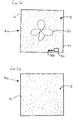
- Figure 5a illustrates schematically a hard (paper) copy of such a digital document.
- the hard copy comprises a carrier 70a in the form of a single sheet of A4 paper, with the machine-readable pattern 12 of dots 14 printed on it.
- the user has defined the pattern area to cover the entire area of the carrier 70a, as can be seen from the figure.
- the content is made up of a schematic image of a flower 72a, the word "SEND" 72b and a check box 72c. The nature and amount of the content will depend entirely on the intended use of the document.
- Such digital documents may be used for specific functions, such as questionnaires or forms, for example.
- Suitable techniques for simultaneously printing a digital pattern and human-discernable content on printers, such as inkjet and laser printers, are more fully described in the co-pending British patent application No. 0321164.6, incorporated by reference herein, entitled “Methods, apparatus and software for printing location pattern", (Hewlett-Packard reference 200300566-1; Attorney docket JL3824).
- the digital documents are printed with no, or substantially no human-discernable content.
- the resultant printed digital documents in such methods are suitable for a wide variety of uses by a user; i.e. they may be used as the digital equivalent of blank notepaper.
- Figure 5b illustrates schematically a hard (paper) copy of such a digital document.
- the hard copy again comprises a carrier 70b in the form of a single sheet of A4 paper, with the machine-readable pattern 12 of dots 14 printed on it.
- the user has defined the pattern area to cover the entire area of the carrier 70b, as can be seen from the figure.
- the user interface of the PC 52 allows a user to the view electronic versions of digital documents to be printed, using a conventional software viewer application, referenced 52f in Figure 3, on the screen 58.
- An already existing, previously designed document may be accessed from a database of such documents for printing.
- a new document may be designed by the user.
- the user may make modifications to the digital documents prior to printing them should this be required. Such changes may include modifying any human-discernable content that may be present in the document or modifying the area or areas, in terms of size or shape for example, on the digital document that are to have digital pattern applied to them.
- This may be achieved through the user interface, which includes the keyboard 54 and mouse 56 and software (not shown) for processing inputs from them, as well as the screen 58 and software 52g for producing the content, e.g. images and/or text, on the screen.
- Figure 4a is a flow diagram showing an exemplary method of designing a generic electronic digital document suitable for use with embodiments of the present invention.
- the method starts at step 2 with the design of the human-discernable content of the document.
- the design work is carried out on the PC using a software application.
- the application may, for example, be Acrobat Reader or a word processing package such as 'Word', a database package such as 'Access', or a spreadsheet package such as 'Excel'.
- Each of these applications may be used to design the content of the document.
- the content is converted to PDF format at step 4. It will be understood that in the event that no human-discernable content is incorporated into the documents, the steps 2 and 4 may be omitted from the method.
- the machine-readable pattern areas of the document are then defined at step 6.
- this is carried out using a form design tool (FDT) 52h, shown in Figure 3, which in the present embodiment is in the form of an Acrobat 5.0 plug-in.
- FDT form design tool
- the machine-readable pattern area of the document may be the entire page; which may be a single A4 sheet for example. This may even be set as the default setting at this step.
- the user allocates any desired computer-implemented functions to one or more areas of pattern in the document.
- a pattern area may code for instructions to perform the associated function.
- a "send" function may be designated by a user to the pattern area associated with the box 72c of the document 70a shown in Figure 5a, for example.
- the system knows that the updating of the document 70a is complete. In one simple case, such a document need have no such computer-implemented functions.
- the user initiates the printing process, by selecting a printing option on a user interface (UI) (not shown).
- UI user interface
- the printing UI the user requests the number of prints and various other printing parameters (e.g. whether the printed document is to be in colour or black and white, etc.).
- the PoD tool 52e identifies from the document file name that the document is a document having a position identifying pattern on it.
- the PoD tool 52e then identifies those printers on the network which the user may select to print the print job, at step 6. In the present example, this includes the printer 60.
- the user selects the printer 60 and initiates the print operation, in a conventional manner, at step 8.
- the printer 60 is a conventional laser printer with a resolution of 600dpi, such as is conventionally used in office environments.
- other types of printer may be used. These may include inkjet printers, LED printers, LCD printers, Liquid Electrophotographic Printers.
- Photocopiers can also be considered as printers. The difference between an electrostatic, toner-based, photocopier and a laser printer is not significant for many aspects of the invention. Indeed, it is not uncommon for computers, e.g. PCs to be configured to print from photocopiers.
- the PoD tool 52f allocates a unique instance ID to the printed document, at step 10. It then requests the required amount of pattern space from the database 52d of pattern data, at step 12, providing the document name and instance ID.
- the requested pattern area is sufficient to cover substantially all of the document, in this example a sheet of A4 paper, as stated above. For other examples, only some areas of the document will need to be allocated a digital pattern.
- An area of pattern is allocated at step 14 to the document from a virtual pattern space stored in the database 52d.
- the PoD tool 52e receives back from the database 52d a definition of the pattern space allocated. In the present embodiment, this is in the form of a co-ordinate reference within the total pattern space. This may take the form of, for example, upper left and lower right co-ordinates of the allocated area in the pattern space.
- the workstation 51 is then able to re-create the dot pattern in the allocated area from that information in a conventional manner.
- a full definition of the actual pattern to be used may be transmitted from the database 52d to the PoD tool 52e. Such a full definition may take the form of co-ordinate positions, for example, of each dot in the allocated area.
- the definition of the dot pattern contains the nominal, or ideal positions of the dots which lie in the allocated pattern space. Furthermore, the size and form of the individual dots in the allocated pattern space are defined only by the specification of the system. In the case of the Anoto system, for example, the dots are circular with a diameter of approximately 100 ⁇ m.
- the PoD tool 52e then obtains, at step 16, data relating to the printing characteristics of the selected printer; printer 60.
- this information is stored locally with respect to the workstation 51, in the memory 52b of the PC 52. In other embodiments, however, this information may be stored on a server connected to a network such as a LAN or the Internet 62.
- the printing characteristics data informs the PoD tool 52e that the printer 60 should print a digital pattern with modified dots, or with a modified dot shape, in order that the printed pattern may be more reliably read by the pen 20.
- the printing characteristics data also defines the modified dot shape for use with the digital pattern.
- the printing characteristics data also defines the position(s) and orientation(s) of the modified dot shape with respect to one or more exemplary virtual grid intersection 16c.
- This information may be used, when generating the digital pattern, to ensure that each of the modified dots in the pattern is correctly positioned and orientated with respect to its corresponding virtual intersection 16c. In this manner, it may be ensured that the pattern may be reliably read by the pen.
- This definition in the present embodiment, is given in the native resolution of the printer 60 and is employed when printing the document with the printer 60.
- FIG. 6a various exemplary parts of digital dot patterns are illustrated.
- four dots 80a-d forming an exemplary part of a digital pattern, printed in a conventional manner with a digital printer of 600dpi resolution, are illustrated.
- the position of the intersections of the imaginary gridlines are indicated by crosses 82.
- the dots 80a-d are located, respectively above, to the right, below and to the left of their adjacent or corresponding crosses 82.
- the figure is shown, for ease of explanation, against an imaginary background grid.
- Each of the individual squares making up the grid represent the smallest individual unit of addressable printable area; i.e. the smallest individual unit of area which may be printed by the printer 60.
- the grid represents the native resolution of the printer.
- each of the pixels which may be printed by the printer 60 substantially fills a given square. It will thus be understood that since the native resolution of the printer 60 is 600dpi, the length of each of the individual squares making up the grid is 42.3 ⁇ m. Similarly, the diameter of each pixel it prints is approximately 42 ⁇ m. It can thus be seen that crosses 82 are separated by their immediate neighbours in the horizontal and vertical directions by 7 individual squares. This equates to 296.3 ⁇ m, which is approximately equal to the 300 ⁇ m as used in the Anoto system.
- the circular dot shape is approximated by a 2 by 2 pixel array, as can be seen in the case of each of the dots 80a-d.
- the minimum diameter of each of the dots 80a-d is approximately 2 x 42 ⁇ m, which gives a diameter of approximately 84 ⁇ m.
- dot offset distance is the distance separating the optical centre of gravity of a given dot from the its adjacent gridline intersection point. It will be understood that the optical centre of gravity of a 2x2 pixel array, such as any one of dots 80a-d, lies at the centre of the 2x2 pixel array. Thus, the "dot offset distance" for dot 80a, for example, is referenced “d” in the figure. As can be seen from the figure, the “dot offset distance” is equal to the width of one individual squares making up the grid; i.e. 42.3 ⁇ m.
- each dot occupies a different position (i.e. above, to the right, to the below and to the left) relative to its corresponding cross, as was the case in Figure 6a.
- each of the Figures 6b-6e is shown, for ease of explanation, against a background grid, where each individual square of the background grid represents the smallest individual unit of area which may be printed by the printer 60.
- the length of the sides of each of the individual squares of the grids shown in Figures 6b-6e is again 42.3 ⁇ m.
- the representations of dot patterns illustrated in Figures 6b-e are schematic, or idealised illustrations. These schematic illustrations may most closely resemble a raster image or bit map of the dots prior to being printed. This may be as generated in application software, such as the PoD tool 52e, or as in the data processed by the printer driver (referenced 52i in Figure 3), prior to being sent to the printer 60. It will of course be appreciated that when the dots are in fact printed, the printed shape of a dot may vary somewhat from the schematic shapes illustrated. This may be due to several factors. One of these is due to imperfections of the print engine, which causes its printed output to be only an approximation of the pre-printed image.
- the dot 84c is made up of four pixels, in the form of a capital "T".
- the remaining dots 84a, 84b and 84d have the same size and shape as the dot 84c (i.e. have the same number and configuration of pixels) but are each but are located at a different orientation relative to their adjacent crosses 82. It will in fact be clear to the skilled reader that rotating the dot 84c, +90, 180 and +270 degrees about its adjacent cross yields the orientational and positional relationship of dots 84d, 84a and 84b, respectively, relative to their respective adjacent crosses.
- FIG. 7a an enlarged view of the dot 84a, is shown.
- the individual pixels forming the dot are referenced W, X, Y and Z. It may be immediately seen from this figure that the optical centre of gravity of the group of pixels X, Y and Z lies at the intersection of the line Y-Y, which passes through the corresponding cross 82, and line X 3 -X 3 , lying perpendicular to line Y-Y. Similarly, it may be seen that the optical centre of gravity of the pixel W lies at the intersection of the lines Y-Y and X 1 -X 1 .
- Simple ratios show that the optical centre of gravity of the whole dot, including pixels W, X, Y and Z lies on the intersection between the lines Y-Y and X 2 -X 2 , which lies parallel to and between the lines X 1 -X 1 and X 2 -X 2 ; where, the distance separating the lines X 2 -X 2 and X 3 -X 3 is one third that separating the lines X 2 -X 2 and X 1 -X 1 .
- the optical centre of gravity of the dot 84a is therefore indicated at point "C". Its distance from the centre of the cross 82 is given by the distance "d", which is equal to 1.25 of the length of an individual square of the grid shown in Figures 6b-6d; i.e. 1.25 x 42.3 ⁇ m, which equals 52.9 ⁇ m. This distance is of course the "dot offset distance". It will be understood that the same value for the "dot offset distance" is obtained in the case of each of the remaining dots 84b, 84c and 84d. It has been found that the modified dot pattern indicated in Figure 6b with the "dot offset distance" of 52.9 ⁇ m results in printed pattern that may be reliably read by the pen 20.
- the "dot offset distance" may be brought within the tolerances of the system.
- a printed digital pattern that conforms to the specifications of the system may be printed with a printer such as printer 60.
- Figure 6c shows an alternative dot pattern.
- dots 86a-d of the same shape and size as described with reference to Figure 6b are employed.
- the positions and orientations of a given dot in the pattern shown in Figure 6c differs from the corresponding dot shown in the Figure 6b.
- the dot 86c which is located offset below its cross.
- This dot is inverted relative to the corresponding dot, dot 84c, of figure 6b which is located offset below its cross.
- this may be view as the stem of the "T" of dots 86a and 86c are directed towards their respective, adjacent crosses, whereas the opposite is true in the case of the dots 84a and 84c.
- the dot 84c is located so as to be symmetrical about the line Y-Y (shown in Figure 7a) which passes through its adjacent cross
- the dot 86c is offset not only below its adjacent cross, but also somewhat to the left, as viewed in the image.
- FIG. 7b An enlarged view of the dot 86a, is shown in Figure 7b. This is illustrated in the same manner that the dot 84a was illustrated in Figure 7a.
- the optical centre of gravity of the dot 86a is illustrated by the cross referenced "C 1 ". This may be determined in the same manner as was used with reference to Figure 7a.
- optical centre of gravity of the dot 86a is again located 1.25 of the length of an individual square of the grid shown in Figures 6b-6d from the cross 82 in the direction Y-Y; i.e. 52.9 ⁇ m.
- "dot offset distance" of 52.9 ⁇ m results in printed pattern that may be reliably read by the pen 20 when printed with a printer such as printer 60.
- optical centre of gravity of the dot 86a is also located a distance "d x " offset in a direction perpendicular to the direction Y-Y; to the left of its cross, as viewed in the figure.
- the distance "d x " in this case is half of the length of an individual square of the grid shown in Figures 6b-6d; i.e. 21.2 ⁇ m. In practice however, this offset distance "d x ", in a secondary direction, has been found to be acceptable for use with the Anoto system in the case of this dot pattern.
- Figure 6d shows a further alternative dot pattern.
- dots 88a-d consisting of three pixels arranged in an "L" shape are used.
- the dots in this dots pattern have the same rotative, positional and orientational relationship relative to their adjacent crosses as do the dots in the pattern shown in Figure 6b.
- the optical centre of gravity of each of the dots 88a-d is offset from its corresponding cross, in both a primary direction and a secondary direction.
- the dot pattern of Figure 6d has been found to work well with the pen 20 when printed using a 600dpi laser printer.
- Figure 6e shows a further alternative dot pattern.
- This dot pattern resembles the dot pattern shown in Figure 6d in that dots 90a-d consisting of three pixels arranged in an "L" shape are used.
- the optical centre of gravity of each of the dots 90a-d is offset from its adjacent cross, in both a primary direction and a secondary direction.
- the dots 90a-d have similar orientational and positional relationships, relative to their adjacent crosses, as is the case with the dots making up the dot pattern illustrated in Figure 6c.
- the dot pattern of Figure 6e has been found to work well with the pen 20 when printed using a 600dpi laser printer.
- Such dot may, for example, use: a different number of pixels per dot to those shown in figures 6b-e; one or more differently shaped dots; dots of a shape different to those given in figures 6b-e; or, different aspects of the patterns given in figures 6b-e.
- any one of the patterns of modified dots illustrated in Figures 6b-e, or indeed a further pattern of modified dots may be specified in the printing characteristics of the printer 60 obtained at step 16 of Figure 4b.
- the PoD tool 52e in conjunction with the workstation 51 re-creates the dot pattern which is to be printed, using the modified dot shape pattern, obtained at step 16, and converts this into a print file ready for printing in a conventional manner.
- the dot pattern which is to be printed is recreated as a bit map, although any other suitable format may instead be used.
- the print file is then converted into a language that can be understood by the printer driver 52i (illustrated in Figure 3) associated with the workstation 51 and is sent to the printer driver 52i.
- a suitable language are PCL5 or Postscript. However, other languages may instead be used.
- the print file is sent to the printer 60, where the document is printed.
- the printer 60 may be a monochrome printer, which typically prints in black ink. Alternatively, it may be a colour printer, typically printing in black and three complementary colour inks. In either case, the digital pattern is printed in the present embodiment using an ink that absorbs light at a non-visible wavelength of light, such that the dots may be read by the pen 20.
- ink is meant to include liquid inks, and powder inks (e.g. toner that needs heat to fuse to a page/surface) and gels: it is not used in a sense to restrict its physical form.
- human-discernable content normally undergoes a half-toning and masking operation prior to printing in order to determine what content, if any, is printed at each pixel of the printing operation.
- the digital pattern may bypass a half-toning operation.
- the pixels of the digital pattern may either be "on” or "off", with no shades of intensity between those extremes.
- the digital pattern data may be sent from a colour separation stage directly to a masking stage, or even directly to the printer.
- the digital document is to be printed on the same carrier as human-discernible content
- the digital pattern may be printed using an ink that absorbs IR radiation and the human-discernable content may be printed using human readable, IR transparent ink. In this manner, the risk of the human-discernable content obscuring or masking the digital pattern may be avoided.
- a four-colour laser or inkjet printer may be used.
- the digital patter is printed using an infra-red absorbing black ink.
- the human-discernable content is printed using cyan, magenta and yellow inks that are not infra-red absorbing.
- the black ink channel is processed separately from the cyan, magenta and yellow channels. In this manner, the human-discernable content and the digital pattern may be maintained separate.
- embodiments of the present invention may be used to permit printers which may otherwise not be able to print a digital pattern sufficiently accurately to be correctly read, by employing dots of a shape which modifies the optical centre of gravity of each dot. In this way, an apparent lack of printer resolution may be compensated for. It will be understood that embodiments of the present invention may be particularly useful in allowing existing printers to be successfully used with such digital pattern systems.
- the characteristics of the modified dots were defined in a bit map, the skilled reader will appreciate that in other embodiments of the invention, this need not be the case.
- the dots or other position determining markings according embodiments of the present invention may be defined using any suitable method that explicitly defines, in the printer's native resolution, the pixels which are to be used in order to print the dots or the position determining markings. For example, this may be achieved using a font set or a high level programming language.
- variable which is used to modify the characteristics of the dots that make up the digital pattern need not be, or need not be only the resolution of the printer.
- Other factors which affect the optical appearance of such dots, and the way in which they are read by a reader such as the pen 20, may include the media type being used. For example, whether the media is glossy or matt, recycled or not recycled, or indeed whether the media is made from non-paper based material, such as acetate.
- the ink characteristics of the printer being used may also affect the appearance of the digital pattern, and the way in which they are read by a reader such as the pen 20.
- a digital pattern with preferred modified dot characteristics may be determined using conventional experimental techniques.
- a number of such operating conditions may be stored in a look up table in the memory of a workstation, such as workstation 51 for example, together with their corresponding preferred modified dot characteristics.
Landscapes
- Engineering & Computer Science (AREA)
- Physics & Mathematics (AREA)
- General Physics & Mathematics (AREA)
- Theoretical Computer Science (AREA)
- General Engineering & Computer Science (AREA)
- Record Information Processing For Printing (AREA)
- Dot-Matrix Printers And Others (AREA)
Applications Claiming Priority (2)
| Application Number | Priority Date | Filing Date | Title |
|---|---|---|---|
| US660323 | 2003-09-10 | ||
| US10/660,323 US20050052706A1 (en) | 2003-09-10 | 2003-09-10 | Location patterns and methods and apparatus for generating such patterns |
Publications (2)
| Publication Number | Publication Date |
|---|---|
| EP1515264A2 true EP1515264A2 (de) | 2005-03-16 |
| EP1515264A3 EP1515264A3 (de) | 2011-05-18 |
Family
ID=34136771
Family Applications (1)
| Application Number | Title | Priority Date | Filing Date |
|---|---|---|---|
| EP04104163A Withdrawn EP1515264A3 (de) | 2003-09-10 | 2004-08-31 | Lokalisierungsmuster und Verfahren und Vorrichtung zur Erzeugung solcher Muster |
Country Status (2)
| Country | Link |
|---|---|
| US (1) | US20050052706A1 (de) |
| EP (1) | EP1515264A3 (de) |
Families Citing this family (11)
| Publication number | Priority date | Publication date | Assignee | Title |
|---|---|---|---|---|
| AUPQ363299A0 (en) * | 1999-10-25 | 1999-11-18 | Silverbrook Research Pty Ltd | Paper based information inter face |
| US7503493B2 (en) * | 1999-10-25 | 2009-03-17 | Silverbrook Research Pty Ltd | Method and system for digitizing freehand graphics with user-selected properties |
| US7322524B2 (en) * | 2000-10-20 | 2008-01-29 | Silverbrook Research Pty Ltd | Graphic design software using an interface surface |
| US7134606B2 (en) * | 2003-12-24 | 2006-11-14 | Kt International, Inc. | Identifier for use with digital paper |
| US20050139666A1 (en) * | 2003-12-24 | 2005-06-30 | Henwell Chou | Verifiable voting input system |
| US7452046B2 (en) * | 2004-10-27 | 2008-11-18 | Hewlett-Packard Development Company, L.P. | Method for preparing a print mask |
| JP4497052B2 (ja) * | 2005-08-12 | 2010-07-07 | 富士ゼロックス株式会社 | 画像処理装置、及びプログラム |
| US20070091369A1 (en) * | 2005-10-21 | 2007-04-26 | Hsue-Yang Liu | Printer and printing method |
| TWI349884B (en) * | 2007-11-14 | 2011-10-01 | Pixart Imaging Inc | Data encryption method implemented on a pattern displaying medium with at least two types of ink |
| US11532490B2 (en) | 2019-08-22 | 2022-12-20 | Micron Technology, Inc. | Semiconductor packages with indications of die-specific information |
| US11031258B2 (en) | 2019-08-22 | 2021-06-08 | Micron Technology, Inc. | Semiconductor packages with patterns of die-specific information |
Family Cites Families (43)
| Publication number | Priority date | Publication date | Assignee | Title |
|---|---|---|---|---|
| US4613945A (en) * | 1984-05-07 | 1986-09-23 | Pitney Bowes Inc. | Method and apparatus for creating fonts for an electronic character generator |
| US4638373A (en) * | 1985-03-06 | 1987-01-20 | Metromedia, Inc. | Method and apparatus for improving gray scale resolution in an ink jet printing system |
| CA1338222C (en) * | 1988-02-15 | 1996-04-02 | Satoshi Iwata | Method and apparatus for energizing thermal head of a thermal printer |
| US5337361C1 (en) * | 1990-01-05 | 2001-05-15 | Symbol Technologies Inc | Record with encoded data |
| US5175694A (en) * | 1990-02-08 | 1992-12-29 | The United States Of America As Represented By The Secretary Of The Navy | Centroid target tracking system utilizing parallel processing of digital data patterns |
| US5522623A (en) * | 1990-03-29 | 1996-06-04 | Technical Systems Corp. | Coded identification card and other standardized documents |
| US5253084A (en) * | 1990-09-14 | 1993-10-12 | Minnesota Mining And Manufacturing Company | General kernel function for electronic halftone generation |
| US5852434A (en) * | 1992-04-03 | 1998-12-22 | Sekendur; Oral F. | Absolute optical position determination |
| US5504695A (en) * | 1992-11-17 | 1996-04-02 | Nissan Motor Co., Ltd. | Apparatus for measuring paint film thickness based on dynamic levelling property of wet paint film surface |
| US5841978A (en) * | 1993-11-18 | 1998-11-24 | Digimarc Corporation | Network linking method using steganographically embedded data objects |
| US5469267A (en) * | 1994-04-08 | 1995-11-21 | The University Of Rochester | Halftone correction system |
| US5634156A (en) * | 1994-12-15 | 1997-05-27 | Eastman Kodak Company | Printing exposure reference |
| US6098882A (en) * | 1996-03-01 | 2000-08-08 | Cobblestone Software, Inc. | Variable formatting of digital data into a pattern |
| DE19653423A1 (de) * | 1996-12-20 | 1998-06-25 | Giesecke & Devrient Gmbh | Druckfarbe |
| US6164847A (en) * | 1997-01-28 | 2000-12-26 | Agfa Corporation | Imaging parameter detection |
| US7054463B2 (en) * | 1998-01-20 | 2006-05-30 | Digimarc Corporation | Data encoding using frail watermarks |
| US6256398B1 (en) * | 1998-08-22 | 2001-07-03 | Kenneth H. P. Chang | Encoding and decoding a message within an image |
| JP2000229397A (ja) * | 1999-02-12 | 2000-08-22 | Riso Kagaku Corp | カラー用孔版印刷装置 |
| US6813039B1 (en) * | 1999-05-25 | 2004-11-02 | Silverbrook Research Pty Ltd | Method and system for accessing the internet |
| AUPQ291299A0 (en) * | 1999-09-17 | 1999-10-07 | Silverbrook Research Pty Ltd | A self mapping surface and related applications |
| US6982798B1 (en) * | 1999-05-25 | 2006-01-03 | Silverbrook Research Pty Ltd | Interface surface printer |
| US6502756B1 (en) * | 1999-05-28 | 2003-01-07 | Anoto Ab | Recording of information |
| SE517445C2 (sv) * | 1999-10-01 | 2002-06-04 | Anoto Ab | Positionsbestämning på en yta försedd med ett positionskodningsmönster |
| US6509903B1 (en) * | 1999-10-06 | 2003-01-21 | Creoscitex Corporation Ltd. | System and method for recording an image |
| SE0000949L (sv) * | 2000-03-21 | 2001-09-22 | Anoto Ab | Positionsinformation |
| US20020048404A1 (en) * | 2000-03-21 | 2002-04-25 | Christer Fahraeus | Apparatus and method for determining spatial orientation |
| US8418052B2 (en) * | 2000-03-21 | 2013-04-09 | Anoto Aktiebolag (Anoto Ab) | Processing of documents |
| US6586688B2 (en) * | 2000-04-05 | 2003-07-01 | Anoto Ab | Information-related devices and methods |
| US6854821B2 (en) * | 2000-04-05 | 2005-02-15 | Anoto Ab | Systems and methods for printing by using a position-coding pattern |
| US7094977B2 (en) * | 2000-04-05 | 2006-08-22 | Anoto Ip Lic Handelsbolag | Method and system for information association |
| US20020050982A1 (en) * | 2000-04-05 | 2002-05-02 | Petter Ericson | Data form having a position-coding pattern detectable by an optical sensor |
| JP2001287330A (ja) * | 2000-04-10 | 2001-10-16 | Olympus Optical Co Ltd | 光学的に読み取り可能なドットのイメージデータ作成方法及びイメージデータ作成装置、並びに記録媒体 |
| US6958747B2 (en) * | 2000-08-30 | 2005-10-25 | Anoto Ab | Method for making a product |
| US7110143B2 (en) * | 2000-12-06 | 2006-09-19 | Xerox Corporation | Accurate printing of proprietary mark patterns and colors |
| JP2002240387A (ja) * | 2000-12-12 | 2002-08-28 | Ricoh Co Ltd | 画像形成方法、画像形成装置及び画像情報管理システム |
| US7649637B2 (en) * | 2001-04-05 | 2010-01-19 | Anoto Ab | Method for printing a global position-coding pattern |
| US6742708B2 (en) * | 2001-06-07 | 2004-06-01 | Hewlett-Packard Development Company, L.P. | Fiducial mark patterns for graphical bar codes |
| US6732927B2 (en) * | 2001-06-26 | 2004-05-11 | Anoto Ab | Method and device for data decoding |
| US6708894B2 (en) * | 2001-06-26 | 2004-03-23 | Xerox Corporation | Method for invisible embedded data using yellow glyphs |
| US6966495B2 (en) * | 2001-06-26 | 2005-11-22 | Anoto Ab | Devices method and computer program for position determination |
| US7175095B2 (en) * | 2001-09-13 | 2007-02-13 | Anoto Ab | Coding pattern |
| US7356012B2 (en) * | 2001-12-27 | 2008-04-08 | Anoto Ab | Method for transmitting information |
| US20040095596A1 (en) * | 2002-11-14 | 2004-05-20 | International Business Machines Corporation | Apparatus, method and program product for controlling printing |
-
2003
- 2003-09-10 US US10/660,323 patent/US20050052706A1/en not_active Abandoned
-
2004
- 2004-08-31 EP EP04104163A patent/EP1515264A3/de not_active Withdrawn
Also Published As
| Publication number | Publication date |
|---|---|
| EP1515264A3 (de) | 2011-05-18 |
| US20050052706A1 (en) | 2005-03-10 |
Similar Documents
| Publication | Publication Date | Title |
|---|---|---|
| US7903281B2 (en) | Methods, apparatus and software for printing location pattern and printed materials | |
| US20050052700A1 (en) | Printing digital documents | |
| US6962450B2 (en) | Methods and apparatus for generating images | |
| US5568248A (en) | Black and white reproducible pattern highlight color printing | |
| US10051156B2 (en) | System and method for producing correlation and gloss mark images | |
| EP1986092A2 (de) | Informationsverarbeitungsvorrichtung, Informationsverarbeitungsverfahren und Computerprogramm | |
| EP1515264A2 (de) | Lokalisierungsmuster und Verfahren und Vorrichtung zur Erzeugung solcher Muster | |
| US9883073B2 (en) | System and method for producing seesaw gloss effect and recording medium with seesaw gloss effect | |
| CN106354441B (zh) | 用于在拼版的多次通过页面上产生透明着色剂的系统和方法 | |
| EP1538550A2 (de) | Lokalisierungsmuster und Verfahren und Vorrichtung zur Erzeugung solcher Muster | |
| US20070091369A1 (en) | Printer and printing method | |
| US10038824B1 (en) | Partitioning raster images for multiple print colorant orders | |
| US8130391B2 (en) | Printing of documents with position identification pattern | |
| JP4715246B2 (ja) | 情報記録装置及び情報処理システム | |
| US9516190B1 (en) | System and method for producing seesaw gloss effect and recording medium with seesaw gloss effect | |
| US9674391B1 (en) | System and method for producing seesaw gloss effect and recording medium with seesaw gloss effect | |
| US20170150002A1 (en) | System and method for producing seesaw gloss effect and recording medium with seesaw gloss effect | |
| JP4565975B2 (ja) | 電子ペン用帳票およびその作成方法 | |
| CN100498586C (zh) | 一种包含防复印底纹的打印文档的打印方法 | |
| JP5114937B2 (ja) | 画像形成装置および印刷物 | |
| EP1665118B1 (de) | Verfahren und vorrichtung zur erzeugung von bildern | |
| US9014579B2 (en) | Image forming apparatus | |
| US20080192295A1 (en) | Generation of Areas of Position Location Pattern | |
| US8264741B2 (en) | Color to black only percent threshold option for customers | |
| WO2005024618A1 (en) | Generation and processing of position identification pattern |
Legal Events
| Date | Code | Title | Description |
|---|---|---|---|
| PUAI | Public reference made under article 153(3) epc to a published international application that has entered the european phase |
Free format text: ORIGINAL CODE: 0009012 |
|
| AK | Designated contracting states |
Kind code of ref document: A2 Designated state(s): AT BE BG CH CY CZ DE DK EE ES FI FR GB GR HU IE IT LI LU MC NL PL PT RO SE SI SK TR |
|
| AX | Request for extension of the european patent |
Extension state: AL HR LT LV MK |
|
| PUAL | Search report despatched |
Free format text: ORIGINAL CODE: 0009013 |
|
| AK | Designated contracting states |
Kind code of ref document: A3 Designated state(s): AT BE BG CH CY CZ DE DK EE ES FI FR GB GR HU IE IT LI LU MC NL PL PT RO SE SI SK TR |
|
| AX | Request for extension of the european patent |
Extension state: AL HR LT LV MK |
|
| RIC1 | Information provided on ipc code assigned before grant |
Ipc: G06F 3/03 20060101ALN20110414BHEP Ipc: G06K 1/12 20060101ALI20110414BHEP Ipc: G06K 15/02 20060101AFI20050111BHEP |
|
| AKY | No designation fees paid | ||
| REG | Reference to a national code |
Ref country code: DE Ref legal event code: R108 |
|
| REG | Reference to a national code |
Ref country code: DE Ref legal event code: R108 Effective date: 20120125 |
|
| STAA | Information on the status of an ep patent application or granted ep patent |
Free format text: STATUS: THE APPLICATION IS DEEMED TO BE WITHDRAWN |
|
| 18D | Application deemed to be withdrawn |
Effective date: 20111119 |