EP1515113A2 - Appareil de mesure de coordonnees a influence reduite de la dilatation thermique - Google Patents
Appareil de mesure de coordonnees a influence reduite de la dilatation thermique Download PDFInfo
- Publication number
- EP1515113A2 EP1515113A2 EP04028612A EP04028612A EP1515113A2 EP 1515113 A2 EP1515113 A2 EP 1515113A2 EP 04028612 A EP04028612 A EP 04028612A EP 04028612 A EP04028612 A EP 04028612A EP 1515113 A2 EP1515113 A2 EP 1515113A2
- Authority
- EP
- European Patent Office
- Prior art keywords
- guide rail
- scale
- bridge girder
- longitudinal direction
- fixed
- Prior art date
- Legal status (The legal status is an assumption and is not a legal conclusion. Google has not performed a legal analysis and makes no representation as to the accuracy of the status listed.)
- Granted
Links
- 239000000523 sample Substances 0.000 claims description 13
- 238000006073 displacement reaction Methods 0.000 claims description 9
- 238000005096 rolling process Methods 0.000 claims description 8
- 230000001419 dependent effect Effects 0.000 description 22
- 238000005259 measurement Methods 0.000 description 14
- XEEYBQQBJWHFJM-UHFFFAOYSA-N Iron Chemical compound [Fe] XEEYBQQBJWHFJM-UHFFFAOYSA-N 0.000 description 12
- 239000004567 concrete Substances 0.000 description 10
- 239000011521 glass Substances 0.000 description 6
- 229910052742 iron Inorganic materials 0.000 description 6
- NJPPVKZQTLUDBO-UHFFFAOYSA-N novaluron Chemical class C1=C(Cl)C(OC(F)(F)C(OC(F)(F)F)F)=CC=C1NC(=O)NC(=O)C1=C(F)C=CC=C1F NJPPVKZQTLUDBO-UHFFFAOYSA-N 0.000 description 6
- 239000002986 polymer concrete Substances 0.000 description 6
- 230000008878 coupling Effects 0.000 description 5
- 238000010168 coupling process Methods 0.000 description 5
- 238000005859 coupling reaction Methods 0.000 description 5
- 239000000463 material Substances 0.000 description 5
- 239000007788 liquid Substances 0.000 description 4
- 230000009471 action Effects 0.000 description 3
- 230000000694 effects Effects 0.000 description 3
- 230000003287 optical effect Effects 0.000 description 3
- 239000006094 Zerodur Substances 0.000 description 2
- 238000005266 casting Methods 0.000 description 2
- 229910010293 ceramic material Inorganic materials 0.000 description 2
- 238000013016 damping Methods 0.000 description 2
- 230000002349 favourable effect Effects 0.000 description 2
- 230000005484 gravity Effects 0.000 description 2
- 229910052500 inorganic mineral Inorganic materials 0.000 description 2
- 239000002184 metal Substances 0.000 description 2
- 229910052751 metal Inorganic materials 0.000 description 2
- 239000011707 mineral Substances 0.000 description 2
- -1 For example Substances 0.000 description 1
- 229910001374 Invar Inorganic materials 0.000 description 1
- 229920000297 Rayon Polymers 0.000 description 1
- 230000008901 benefit Effects 0.000 description 1
- 239000004918 carbon fiber reinforced polymer Substances 0.000 description 1
- 230000002996 emotional effect Effects 0.000 description 1
- 230000007717 exclusion Effects 0.000 description 1
- 238000007572 expansion measurement Methods 0.000 description 1
- 239000010438 granite Substances 0.000 description 1
- 230000006872 improvement Effects 0.000 description 1
- 238000009434 installation Methods 0.000 description 1
- 239000000696 magnetic material Substances 0.000 description 1
- 238000004519 manufacturing process Methods 0.000 description 1
- 230000010355 oscillation Effects 0.000 description 1
- 230000003534 oscillatory effect Effects 0.000 description 1
- 230000009467 reduction Effects 0.000 description 1
- 230000003319 supportive effect Effects 0.000 description 1
- 239000000725 suspension Substances 0.000 description 1
Images


Classifications
-
- G—PHYSICS
- G01—MEASURING; TESTING
- G01B—MEASURING LENGTH, THICKNESS OR SIMILAR LINEAR DIMENSIONS; MEASURING ANGLES; MEASURING AREAS; MEASURING IRREGULARITIES OF SURFACES OR CONTOURS
- G01B5/00—Measuring arrangements characterised by the use of mechanical techniques
- G01B5/0011—Arrangements for eliminating or compensation of measuring errors due to temperature or weight
- G01B5/0014—Arrangements for eliminating or compensation of measuring errors due to temperature or weight due to temperature
-
- G—PHYSICS
- G01—MEASURING; TESTING
- G01B—MEASURING LENGTH, THICKNESS OR SIMILAR LINEAR DIMENSIONS; MEASURING ANGLES; MEASURING AREAS; MEASURING IRREGULARITIES OF SURFACES OR CONTOURS
- G01B5/00—Measuring arrangements characterised by the use of mechanical techniques
- G01B5/0011—Arrangements for eliminating or compensation of measuring errors due to temperature or weight
-
- G—PHYSICS
- G01—MEASURING; TESTING
- G01B—MEASURING LENGTH, THICKNESS OR SIMILAR LINEAR DIMENSIONS; MEASURING ANGLES; MEASURING AREAS; MEASURING IRREGULARITIES OF SURFACES OR CONTOURS
- G01B5/00—Measuring arrangements characterised by the use of mechanical techniques
- G01B5/004—Measuring arrangements characterised by the use of mechanical techniques for measuring coordinates of points
- G01B5/008—Measuring arrangements characterised by the use of mechanical techniques for measuring coordinates of points using coordinate measuring machines
Definitions
- the invention relates to a coordinate with a spatially movable scanning head for scanning a a measuring pad can be arranged to be measured object.
- Such a coordinate measuring device is used for measuring Surface coordinates or contours of the to be measured Object, with a Tastende the scanning head in the vicinity by or in contact with a variety of points on the Surface of the object is brought and in contact with or approaching this surface the deflection of the Tasting with respect to a reference position, for example a zero point of the Meßauflage, is detected. From one Variety of such suitably conducted measurements can then the surface of the object is reconstructed as a dataset become.
- the tactile can be used for measurement either in direct contact be brought with the object, this contact by Deflection of the keyway from a rest position or actuation Registered with the keying coupled switch becomes. It can also perform the measurement without contact when the tip of the probe hits the surface of the object is only approximated and the Tasting via a non-contact approach registration has, for example, by means of a laser or ultrasonic sensor.
- Conventional coordinate measuring devices include for spatial Moving the scanning head including a socket for Setting up on a base, a viewing direction of above on both sides of the measuring pad and above the measuring pad arranged pair of parallel guide rails, at which in the longitudinal direction slidably a bridge girder is stored.
- the Probe On the bridge girder in turn is the Probe in the longitudinal direction of the bridge girder and in Vertical direction for scanning the object slidably supported.
- the measuring range of the coordinate in the vertical direction is determined by the height, with which the two Guide rails are arranged above the Meßauflage, so that the base of the pad to the guide rails extends over a height corresponding to the extent of the Measuring range in the vertical direction corresponds approximately. Thermal actions on this pedestal can result that the two guide rails themselves on different Heights are arranged and thus the measurement is falsified. Temperature gradients in the range of Sockets have a tilting of the rails from the Horizontal results, what the measurement accuracy also limited.
- the base comprises a skeleton for placing on the base and four vertically upwardly extending support rods on which the guide rails are stored.
- the support rods are off a material with the lowest possible thermal expansion coefficient made, so that temperature changes a comparatively small influence on the Height and horizontal alignment of the guide rails to have.
- the base comprises a supported on the skeleton Concrete body with recesses in which the Support rods are arranged. The concrete body isolates the Support rods thermally against the environment, so that too As a result, temperature influences are suppressed.
- a scale attached which of one of the bridge girder worn scanning sensor is read.
- a scale attached which of another scanning sensor is read, which is held on a carriage is which displaces the probe in the vertical direction wearing.
- the scale on the guide rail or the bridge girder is made of a glass with low thermal expansion, wherein the guide rail or the bridge girder made of a material that is one in comparison to the glass scale has greater thermal expansion.
- the glass scale is in the range of a longitudinal end the same on the guide rail or to the bridge girder set while the remaining areas of the scale in The longitudinal direction of the same displaceable on the guide rail or the bridge carrier are stored.
- the invention is based on a Coordinate measuring machine with a pedestal for installation a pad, which is generally approximately horizontal is aligned, this in principle however not to be got to.
- a coordinate measuring machine On the coordinate measuring machine is also an area for Arrangement of the object to be measured provided, which is referred to below as Meßauflage.
- the measuring pad may be part of the coordinate and, for example comprise a measuring table, which is arranged on the base.
- the Meßauflage but also of the Coordinate be different, for example when the object to be measured is arranged directly on the base becomes.
- the coordinate measuring machine further includes a pair with each other parallel guide rails, which in the direction of are arranged above both sides of the Meßauflage and which arranged at a horizontal viewing direction above the Meßauflage are.
- a bridge girder extends transversely between the guide rails and is in the longitudinal direction slidably mounted on these. At the bridge girder is the probe in the vertical direction and in the longitudinal direction slidably supported by the bridge girder.
- the guide rails are vertically extending over themselves Support rods supported on the base in the vertical direction and in the horizontal direction elastically on the base in one Rest position held.
- the invention is based on an idea based on the following Consideration for the reduction of Temperature influences designed arrangement with vertical Supporting the guide rails via support rods on the Pedestal and elastic fixing in a horizontal direction is based on the base: It occur in this arrangement Vibrations of the guide rails in the horizontal direction relative to the pedestal, so that these horizontal vibrations limit the accuracy and the desired increase of the measurement accuracy by the exclusion of temperature influences therefore not to the expected extent is reached.
- the invention proposes to achieve to provide at least one viscous damper, the comprises two components, between which a viscous medium for damping a relative movement of the two components is provided to each other, wherein one of the components of Viscose damper is coupled to the base and the other Component of Viskosedämpfers such with the guide rail coupled with them is that emotional.
- the measurement accuracy limiting Vibrations of the guide rail relative to the Base steamed, so that the measures to reduce Temperature influences finally to an improvement of the Lead measuring accuracy.
- the Viskosedämpfung is therefore advantageous because on the one hand slowly taking place Changes in relative position between guide rail and base due to temperature changes without Generation of about mechanical stresses gives way and on the other hand movements, such as oscillatory movements, attenuates. This leads to a quieter suspension of the scanning head at the coordinate and thus to an increased Measurement accuracy.
- At least one of the support rods is pivotable supported on the base, in such a way that he in a direction of extension of the guide rail is pivotable parallel plane.
- Alternative or supplementary for this purpose it is also advantageous that the support rod in this plane pivotable on the guide rail is articulated.
- one of the support rods is part of the viscous damper, so that vibrations in the support bar itself become integral be steamed.
- a spring assembly provided, one side of which at the top of the Socket is set.
- the other side of the spring is then directly or indirectly coupled to the guide rail, wherein a coupling with an upper portion of the support rod is preferred, which then turn on the guide rail is fixed.
- the spring assembly couples the guide rail such to the base, that elastic deflections in the extension direction the guide rail are possible, wherein the guide rail transverse to the extension direction of the same essentially rigidly coupled to the upper portion of the socket is.
- the spring arrangement, the guide rail in both Horizontal directions elastically deflectable at the top Part of the socket couples, more preferably, in the direction the extension direction of the guide rail a softer spring action is provided than across the Extension direction of the guide rail.
- the invention is based on a Coordinate measuring device with a view from above on both sides the Meßauflage and at a distance in the vertical direction of this arranged pair of parallel guide rails, one across the guide rails themselves extending and slidable on these in the longitudinal direction mounted bridge girder and one at the Bridge girder in the longitudinal direction and in the vertical direction slidably held Tastkopf.
- the coefficient of thermal expansion of the Thermal expansion coefficient of the guide rail or the Bridge carrier is different.
- the invention is based on the knowledge, that the displacement of a not on the guide rail or the bridge carrier specified area of Scale due to thermal influences to an increase contributes to the measurement error.
- the invention proposes in this regard that a scale in the longitudinal direction central area of the scale at the Guide rail or the bridge support is fixed and areas on both sides of this defined area the scale relative to the guide rail or the Bridge girder in effetstablteilsoplasty are displaced.
- a special advantage is the central definition the yardsticks when the coordinate measuring a turntable having.
- Such a turntable allows a twist of the arranged on the turntable to be measured Object relative to the scanhead about one substantially vertically extending axis of rotation. It is then the central area of the scale, attached to the guide rail or the bridge carrier is fixed, with respect to the center of rotation the turntable aligned, in the direction of view perpendicular to the extension direction of the scale. In particular, aligned in this line of sight, the center of the fixed range of the scale with the axis of rotation of the Turntable. It is then the axis of rotation of the turntable largely unaffected by temperature changes always in the same place in the measuring coordinate system of Coordinate measuring.
- the center of the guide rail attached scale also midway between the two arranged the support rails supportive support rods, and the center of the scale attached to the bridge girder is preferably centrally between the guide rails appropriate.
- the on the guide rail or the bridge girder in seeminglystablteilscardi fixed range of the scale is transverse
- Such Holder is preferably realized with a roller bearing.
- the scale in his Areas away from the designated area acrossroisstablibilscardi with respect to the guide rail or the Bridge girder is set to one as possible to achieve tension-free mounting of the scale. Too this purpose is the yardstick in these distant areas but also preferably again in the direction of the vertical direction held displaceable, for which, more preferably, also a roller bearing is provided.
- roller bearings preferably comprise a scale-side rolling surface and a guide rail side or bridge carrier side rolling surface, wherein between the two rolling surfaces at least one and preferably a plurality of balls is arranged.
- the two rolling surfaces by Magnetic force are pressed against the balls, for which purpose preferably one of the two rolling surfaces by a permanent magnet is formed and the other rolling surface by a magnetic material, for example iron, is formed.
- a coordinate measuring machine 1 shown in FIG. 1 corresponds in its basic structure that disclosed in document DE 198 21 274 A1 Coordinate, the disclosure of this Document by including in its full extent in the embodiment described herein, and comprises a base 3 with feet 5 for setting up the coordinate 1 on a floor.
- the base 3 has a U-shaped structure, wherein in a central region a measuring table 7 is arranged is to place thereon an object to be measured.
- the Measuring table 7 includes a turntable 139, on the surface thereof 141 the object to be measured come to the arrangement can.
- the turntable 139 serves to arrange the one on it Object relative to the rest of the coordinate to a to rotate vertically extending axis of rotation 131.
- the Axis of rotation 131 is approximately centered with respect to the measuring support 7, however, the axis of rotation can also be next to the center the Meßauflage, that is outside the center of the U-shaped Structure of the base, to be arranged.
- each Cheek 9 On both sides of the measuring table 7 extends one each Sidewall 9 of the base 3 upwards, with the top of each Cheek 9 each have a guide rail 11 of a Ceramic material is attached.
- the guide rails 11 are aligned horizontally and parallel to each other and extend in a designated y in Figure 1 Direction.
- the position of the Tastendes 29 in the x direction is over a attached to the bridge girder 17 scale 31 and a attached to the guide carriage 23 and the scale 31st reading optical pickup 33 detected while the Position of the keyway 29 in the Z direction over one on the Quill 25 attached scale 35 and an associated to the guide carriage 23 mounted optical scanning head 37 is detected.
- the visible in Figure 1 from the outside shell of the base 3 is formed by a polymer concrete body 41 which surrounds a 2 apparent core 43 of the base 3 mounted around is.
- the core 43 of the base 3 comprises one a plurality of double-T-beams 45 formed base frame 47 at the feet 5 are mounted on vibration damper 49.
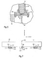
- a flange 51 is attached to the upper side in each case, which is shown in FIG. 3 is shown in detail.
- the flange 51 is at the Double T-beams 45 fastened by means of screws 53.
- In the Flange 51 is inserted from above a tube 55 and firmly held the flange 51.
- the from the base frame 47, the flanges 51 and the tubes 55 existing core 43 of the base 3 is of the polymer concrete of the polymer concrete body 41 cast around, wherein the Tubes 55 thus within the polymer concrete body 41st extend and wherein upper ends 63 of the tubes 55 and a upper surface 89 of the polymer concrete body at the top with each other finish flush.
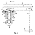
- a support rod 61 is formed in the center of the flange 51 in the center of the flange 51 in the center of the flange 51 in the center of the flange 51 in the center of the flange 51 in the center of the flange 51 in the center of the flange 51 in the center of the flange 51 in the center of the flange 51 in the center of the flange 51 in the center of the flange 51 in the center of the flange 51 is an upwardly conical expanding bearing surface 57 for a lower spherical end 59 a support rod 61 is formed in the Z direction over the end 63 of the tube 55th out, and at an upper end of the support rod 61 is a Flange 65 screwed, as a support for the guide rail 11 serves.
- the crowned end 59 of the support rod 61 puts this over the conical surface 57 on the base frame 47 of the base 3 in y direction, wherein the spherical end 59 together with the conical surface 57, however, a pivot bearing for the Support rod 61 forms, so that this in one in Figure 4 with a direction indicated by arrow 67 around the flange 51 in FIG a yz-plane from the vertical is deflected.
- the upper flange 65 is shown in detail in FIG and comprises a clamping member 69 with a circular bearing surface 71 for engagement with an outer shell of the support rod 61 at its upper end, wherein by means of two in holes 73 and tapped holes 75 screwed screws (in Figure 5 is not shown), the clamping part 69 at the top End of the support rod 61 is clamped.
- the clamping part 69 is about two thin webs 77 with a support member 79 of the Flange 65 connected to the guide rail 11, wherein at the support member 79 has a bore 81 for a screw 83 for Connection with the guide rail 11 is provided.
- the two thin webs 77 are on opposite sides arranged the flange 65, so that a connecting line between the two webs 77 extends in the X direction.
- the two webs 77 each form an elastic connection between the support part 79 and the clamping part 69 the flange 65, so that through the two webs 77 together the support rod 61 is pivotally coupled to the guide rail 11 is, with a deflection of the rod 61 to the upper flange 65 in a in Figure 4 with an arrow 85th indicated direction in the yz plane from the vertical out can take place.
- each support rod 61 about the lower flange 51 in FIG the direction 67 is deflectable and around the upper flange 65th in direction 85 is deflectable, which can be over two Support rods 61 supported guide rail 11 with respect to the Base 3 can be moved in parallel in the y-direction, and she can around the rest position shown in Figure 4 with vertical Orientation of the support rods 61 are deflected. Furthermore, the guide rail 11 with respect to the Thermally extend base 3, with the upper ends of the two support rods 61 are spread apart from each other.
- FIG. 6 shows a detail of a spring arrangement 87, by the upper end of each support rod 61 to the with the upper end 63 of the tube 61 flush upper surface 89th of the concrete body 41 is coupled.
- the spring assembly 87 is punched out of a rectangular sheet metal and in bent in the manner shown in Figure 6.
- the sheet metal 90 has two side portions 96 each having two holes 91 for fastening the spring assembly 87 to the concrete body 61 by means of screws 93.
- a central region 95 of the sheet 90 has two upwards curved cheeks 97 for attachment to the upper flange 65th on.
- 97 two slots 99 are in each cheek 99th for screws provided in blind holes 101 on the Clamping 69 of the upper flange 65 are screwed.
- About the raised at the central area 95 cheeks 97 of the sheet 90 couples the spring assembly 87 the Guide rail 11 in the X direction on the concrete body 41 of the Base 3, wherein the spring assembly 87 for this coupling provides a relatively hard spring constant in the X direction.
- a cavity 105 is formed liquid-tight, which is limited to the concrete body 41 down through the lower flange 51 and to the sides through the tube 55 and open at the top.
- the support rod 61 is at a distance from the tube 55, wherein the gap between tube 55 and support rod 61 is filled with a viscous liquid 107.
- the viscosity of the liquid is about 20,000 mm / sec 2 , and the liquid may be formed by a suitable oil or synthetic liquid of the appropriate viscosity.
- This arrangement acts as a viscous damper between the guide rail 11 and base 3, wherein the support rod 61 forms a first component of the viscous damper coupled to the guide rail 11 and the tube 55 embedded in the concrete body 41 acts as a second component of the viscous damper connected to the base 3.
- the scale 21 consists of Zerodur, a glass material with a thermal expansion coefficient from almost zero.
- the ceramic material manufactured guide rail 11 has a Thermal expansion coefficient greater than that of the Glass scale 21.
- On the guide rail 11 are two Magnets 113 set, which is a horizontally oriented have polished surface 115. Lie on each surface 115 three balls 117, on which in turn an iron plate 119th with a polished horizontal surface rests.
- the Iron plates 119 are attached to the scale 21, namely centered around its Bessel points 121. against the effect of gravity is the scale 21 thus at its Bessel points 121 supported so that due to the gravity effect gives a minimum deflection of the scale 21.
- the magnets 113 and the attracted by these Iron plates 119 the scale 21 is thus in the Z direction the guide rail 11 fixed, but in the y direction displaceable with respect to the guide rail 11 supported.
- a further iron plate 123 glued so that one of their vertically extending side surfaces 123 in a symmetry plane 125 of the scale 21 is arranged, which extends in the Z-X direction.
- On the surface 123 lie two balls 126 with their one side, while on its other side a fixed to the guide rail 11 Magnet 127 is applied and by its magnetic action pulled against the attached to the scale 21 iron plate 121 becomes.
- the plane of symmetry 125 of the scale 21 is also still symmetrical to the guide rail 11 supporting support rods 61 arranged, so z. B. in the middle between the upper Flanges 65 or screws 83.
- the plane of symmetry 125 that is, the area where the Scale 21 is fixed to the guide rail L is in particular also a plane of symmetry with respect to thermal expansion of the scale 21 relative to Guide rail 11. This means that thermal expansions the scale symmetrical to the plane of symmetry 125th take place, even if the lengths of the scale starting from the plane of symmetry 125 to its two ends geometrically different from each other.
- the symmetry plane the scale is the rest of the coordinate aligned such that the axis of rotation 131 of the turntable 139 is contained therein. This is the center of the Turntable in the y-direction of the coordinate system of the coordinate largely independent of temperature changes always arranged in the same place.
- the scale 21 blows up, that is it is between the Surface of the guide rail 11 and the assigning this Surface of the scale 21 an oil layer is introduced, which provides an adhesion force, so that the Scale 21 does not detach from the guide rail 11.
- the scale 21 is at its center on the guide rail 11 in its longitudinal direction (y-direction) fixed, but displaceable in the z direction.
- the magnet 127 is arranged on the guide rail 11, that the plane of symmetry 125 of the scale 21 is seen in the X direction perpendicular over a center of the measuring table 7 and the rotation axis 131 of the turntable 139 is arranged is (see Figure 4).
- the scale 31 is on the bridge girder 17 in a manner attached, the attachment of the scale 21 at the Guide rail 11 is analog.
- the attachment of the scale 31 to the bridge girder 17 takes place as well as this in Figure 7 for the scale 21 on the guide rail eleventh is shown, so that its own representation of Attachment of the scale 31 on the bridge girder 17 is unnecessary.
- the scale 31 has a plane of symmetry 135, which at Magnolia in the y-direction perpendicular to the center of the measuring table. 7 or the axis of rotation 131 of the turntable 139 is arranged, so that also in determining the position of the key 29 in the X direction, the reading of the scale 31 also at different temperatures to very low measurement errors leads.
- center of the scale 31 is also centrally between arranged the two guide rails 11 so that the Scale 31 itself symmetrically with respect to the guide rails 11 is arranged.
- the above-described embodiment of the invention is particularly advantageous in that the support rods 61, which indeed have the function, the guide rail 11 to support the base 3 vertically, at the same time be used as components of Viskosedämpfers. It is on the other hand also conceivable independent of the support rods 61 Viskosedämpfer between guide rail 11 and Socket 3 provide. In such a case, no liquid-tight space can be provided in the socket, which in particular when the cheeks 9 of the base 3 as Mineral casting 41 are made, simplifies the production.
- a Scale in particular over a center of the measuring range or a rotation axis of a turntable, also on a coordinate measuring machine to insert, which of the preceding deviates described embodiment.
- a coordinate measuring machine whose two guide rails not via support rods 61 but differently on the base are supported.
- this is also a coordinate measuring machine, which is not a pair of guide rails 11, but only a single guide rail for displacement of the keying in the y direction.
- the support rods are made of Invar steel. But there are others too Materials favorable, which has a low coefficient of thermal expansion exhibit. Examples are Zerodur and certain carbon fiber reinforced plastics. Instead of of polymer concrete can also be other materials, such as For example, granite, mineral casting or other concretes used be to form the pedestal.
- the spring assembly 87 shown in Figure 6 couples the Guide rail 11 to the base 3 with spring constants, the are less in the y-direction than in the x-direction. It is the other way also conceivable, the guide rail 11 also in the x direction with a lower spring constant to the socket To couple 3, including, for example, the spring assembly then the bulged areas 103 corresponding transversely arranged may include more bulging areas to the To keep cheeks 97.
- the viscosity of the viscous medium of the predefined value deviations depending on the geometric Design of the Viskosedämpfers can therefore significantly larger or smaller values of the viscosity can be selected.
- the invention provides inter alia in a first independent Embodiment a coordinate with a spatially movable scanning head for scanning a a measuring object can be arranged to be measured, which includes: a pedestal to set up on a horizontal Underlay, a - seen from above - on both sides of the Measuring support and at a distance in the vertical direction of this arranged pair of parallel guide rails, a transverse to the guide rails extending and slidably mounted on these in the longitudinal direction Bridge girder, and at the bridge girder in the Held longitudinally and displaceable in the vertical direction Probe for scanning the object, wherein between an area of the base and the guide rails Support rods extend substantially vertically, over the the guide rails supported on the base in the vertical direction are at least one area of each Guide rail on the base in at least one horizontal direction elastically held in a rest position is, wherein at least one viscous damper with a to the Socket coupled first component and one together with the guide rails relative to the base in the horizontal direction provided
- Under one of the first independent embodiment dependent Second embodiment is a coordinate measuring machine provided, wherein at least one of the support rods in one to the extension direction of the guide rail parallel plane pivotally supported on the base is.
- a coordinate measuring device is provided, wherein at least one of the support rods in a for Extension direction of the guide rail parallel plane pivotally hinged to the guide rail.
- Under one of the first independent embodiment or the second or third dependent embodiment dependent fourth embodiment is a coordinate measuring machine provided, wherein one of the two components the Viskosedämpfers comprises a support rod.
- Fifth embodiment is a coordinate measuring machine provided, wherein an upper portion of the support rod, the part of the viscous damper is on the guide rail in the horizontal direction is fixed.
- Under one of the fourth or fifth dependent Embodiment-dependent sixth embodiment is a Coordinate measuring device provided, wherein a lower area of the support rod which is part of the viscous damper on which Base is set in the horizontal direction.
- a coordinate measuring machine provided, wherein the support rod at a lower area the base is supported and an upper area of the Sockels surrounds at least a portion of the support rod to to thermally isolate it from an environment.
- first component of the Viskosedämpfers includes the upper portion of the base and the second component of the Viskosedämpfers that of the upper region of the Sockels encompassed part of the bar comprises.
- a Coordinate measuring device provided, one with its one Side coupled to the upper portion of the base spring assembly is provided to the area of the guide rail in the at least one horizontal direction to keep elastic.
- Tenth embodiment is a coordinate measuring machine provided, the other side of the spring assembly is coupled to an upper portion of the support rod.
- twelfth embodiment is a coordinate measuring machine provided, wherein the spring arrangement for mounting in Extension direction of the guide rail a softer Spring force provides as transverse to the direction of extension the guide rail.
- a coordinate measuring device is provided, wherein the spring arrangement the area of the guide rail in the extension direction same elastic holds and the area of Guide rail transversely to the extension direction of the same in essentially rigidly coupled to the upper portion of the base is.
- a central portion (125) thereof is on the guide rail (11), wherein the on the guide rail (11) fixed area (125) of the scale over a center (131) of the Meßauflage (7) is arranged.
Landscapes
- Physics & Mathematics (AREA)
- General Physics & Mathematics (AREA)
- A Measuring Device Byusing Mechanical Method (AREA)
- Length Measuring Devices With Unspecified Measuring Means (AREA)
Applications Claiming Priority (3)
| Application Number | Priority Date | Filing Date | Title |
|---|---|---|---|
| DE10047953 | 2000-09-27 | ||
| DE10047953 | 2000-09-27 | ||
| EP01985748A EP1320719B1 (fr) | 2000-09-27 | 2001-09-27 | Appareil de mesure de coordonnees comportant un amortisseur a milieu visqueux, a influence reduite de la dilatation thermique |
Related Parent Applications (1)
| Application Number | Title | Priority Date | Filing Date |
|---|---|---|---|
| EP01985748A Division EP1320719B1 (fr) | 2000-09-27 | 2001-09-27 | Appareil de mesure de coordonnees comportant un amortisseur a milieu visqueux, a influence reduite de la dilatation thermique |
Publications (3)
| Publication Number | Publication Date |
|---|---|
| EP1515113A2 true EP1515113A2 (fr) | 2005-03-16 |
| EP1515113A3 EP1515113A3 (fr) | 2005-03-23 |
| EP1515113B1 EP1515113B1 (fr) | 2009-11-11 |
Family
ID=7657890
Family Applications (2)
| Application Number | Title | Priority Date | Filing Date |
|---|---|---|---|
| EP01985748A Expired - Lifetime EP1320719B1 (fr) | 2000-09-27 | 2001-09-27 | Appareil de mesure de coordonnees comportant un amortisseur a milieu visqueux, a influence reduite de la dilatation thermique |
| EP04028612A Expired - Lifetime EP1515113B1 (fr) | 2000-09-27 | 2001-09-27 | Appareil de mesure de coordonnees a influence reduite de la dilatation thermique |
Family Applications Before (1)
| Application Number | Title | Priority Date | Filing Date |
|---|---|---|---|
| EP01985748A Expired - Lifetime EP1320719B1 (fr) | 2000-09-27 | 2001-09-27 | Appareil de mesure de coordonnees comportant un amortisseur a milieu visqueux, a influence reduite de la dilatation thermique |
Country Status (3)
| Country | Link |
|---|---|
| EP (2) | EP1320719B1 (fr) |
| DE (3) | DE50115220D1 (fr) |
| WO (1) | WO2002027265A2 (fr) |
Families Citing this family (6)
| Publication number | Priority date | Publication date | Assignee | Title |
|---|---|---|---|---|
| JP4302440B2 (ja) | 2003-06-12 | 2009-07-29 | 株式会社ミツトヨ | 測定機 |
| DE102004011730A1 (de) | 2004-03-05 | 2005-09-22 | Carl Zeiss Industrielle Messtechnik Gmbh | Tastkopf für ein Koordinatenmessgerät |
| DE102006036377A1 (de) * | 2006-08-02 | 2008-02-07 | E. Zoller GmbH & Co. KG Einstell- und Messgeräte | Einstell-, Mess- und/oder Werkzeugspanngerät |
| DE102013106059B4 (de) | 2013-06-11 | 2019-12-19 | Carl Zeiss Industrielle Messtechnik Gmbh | Koordinatenmessgerät zum Vermessen von Werkstücken |
| DE102014218483B4 (de) * | 2014-09-15 | 2016-10-13 | Deckel Maho Pfronten Gmbh | Positionsmesseinrichtung zum Einsatz an einer Werkzeugmaschine |
| ES2621078T3 (es) | 2014-11-26 | 2017-06-30 | Dr. Johannes Heidenhain Gmbh | Dispositivo de medición de longitud |
Family Cites Families (7)
| Publication number | Priority date | Publication date | Assignee | Title |
|---|---|---|---|---|
| DE3316081A1 (de) * | 1983-05-03 | 1984-11-08 | Dr. Johannes Heidenhain Gmbh, 8225 Traunreut | Messeinrichtung |
| DD248865A1 (de) * | 1986-05-05 | 1987-08-19 | Zeiss Jena Veb Carl | Verfahren und einrichtung zum messen von laengen an messobjekten |
| US4763420A (en) * | 1987-10-06 | 1988-08-16 | Brown & Sharpe Manufacturing Company | Base assembly for coordinate measuring machine |
| US4815213A (en) * | 1987-10-09 | 1989-03-28 | Brown & Sharpe Manufacturing Co. | Apparatus for temperature compensation of sensing means of a machine |
| US6000671A (en) * | 1997-01-29 | 1999-12-14 | Advanced Isolation Systems, Ltd. | Vibration isolation system |
| DE19821274A1 (de) * | 1998-05-13 | 1999-11-18 | Zeiss Carl Fa | Koordinatenmeßgerät in Brückenbauweise |
| DE29810618U1 (de) * | 1998-06-12 | 1998-08-20 | Fa. Carl Zeiss, 89518 Heidenheim | Dämpfungsvorrichtung für Koordinatenmeßgeräte |
-
2001
- 2001-09-27 WO PCT/EP2001/011218 patent/WO2002027265A2/fr not_active Ceased
- 2001-09-27 DE DE50115220T patent/DE50115220D1/de not_active Expired - Lifetime
- 2001-09-27 EP EP01985748A patent/EP1320719B1/fr not_active Expired - Lifetime
- 2001-09-27 DE DE10147614A patent/DE10147614A1/de not_active Withdrawn
- 2001-09-27 DE DE50109509T patent/DE50109509D1/de not_active Expired - Lifetime
- 2001-09-27 EP EP04028612A patent/EP1515113B1/fr not_active Expired - Lifetime
Also Published As
| Publication number | Publication date |
|---|---|
| WO2002027265A2 (fr) | 2002-04-04 |
| DE50115220D1 (de) | 2009-12-24 |
| EP1320719B1 (fr) | 2006-04-12 |
| DE50109509D1 (de) | 2006-05-24 |
| WO2002027265A3 (fr) | 2002-09-06 |
| EP1515113B1 (fr) | 2009-11-11 |
| EP1320719A2 (fr) | 2003-06-25 |
| EP1515113A3 (fr) | 2005-03-23 |
| DE10147614A1 (de) | 2002-04-11 |
Similar Documents
| Publication | Publication Date | Title |
|---|---|---|
| DE68914148T2 (de) | Messsonde mit Lagern, deren Rollelemente zentralisiert sind. | |
| EP1462760B1 (fr) | Dispositif de mesure de la position d'un capteur dans une machine de mesure de coordonnées | |
| EP0957332B1 (fr) | Machine de mesure de coordonnées de type portique | |
| DE112010002189B4 (de) | Kontaktfreies dreidimensionales Ultrapräzisions-Tastsystem basierend auf einer sphärischen kapazitiven Platte | |
| DE3815198C2 (de) | Koordinatenmeßgerät | |
| DD259056A5 (de) | Einrichtung zum abtasten der oberflaeche eines gegenstandes | |
| EP1996898A1 (fr) | Corps d'essai et procede de calibrage d'un appareil de mesure de coordonnees | |
| EP2018511A2 (fr) | Machine de mesure ou d'usinage de pièces, notamment appareil de mesure de coordonnées | |
| DE3426315C2 (de) | Zahnmeßtaster | |
| EP1320719B1 (fr) | Appareil de mesure de coordonnees comportant un amortisseur a milieu visqueux, a influence reduite de la dilatation thermique | |
| EP1721118B1 (fr) | Tete de palpage pour un appareil de mesure de coordonnees | |
| EP1381823B1 (fr) | Support pour appareil de mesure de coordonnees | |
| DE29822001U1 (de) | Prüfkörper zur Kalibrierung eines Koordinatenmeßgerätes | |
| EP1684059B1 (fr) | Dispositif pour générer et mesurer avec une haute précision des forces et des déplacements | |
| EP2734807A1 (fr) | Appareil de mesure de coordonnées équipé d'un dispositif à tubes communicants | |
| DE29612475U1 (de) | Tastkopf | |
| DE3118612A1 (de) | "einrichtung zur ankopplung eines messtisches an das grundgestell einer messmaschine" | |
| DE102010006505B4 (de) | Koordinatenmessgerät mit passivem Dreh-Schwenk-Mechanismus | |
| DE3313861C2 (de) | Halterung für ein Paar von Planspiegeln und eine Kugel in einer Interferometer-Längenmeßeinrichtung | |
| DE102013106059A1 (de) | Koordinatenmessgerät zum Vermessen von Werkstücken | |
| DE10040277C2 (de) | Kreuztisch zur Bereitstellung von Bewegungen in einem zweidimensionalen Koordinatensystem | |
| EP1738134A1 (fr) | Appareil de mesure de coordonnees servant a determiner une coordonnee sur un objet de mesure par une technique de mesure | |
| WO2012095430A1 (fr) | Procédé et système destinés à étalonner des capteurs renvoyant des valeurs de mesure, lesquels équipent un appareil de mesure de coordonnées tactile | |
| DD226367A1 (de) | Anordnung zur erhoehung der steifigkeit von tastkoepfen | |
| DE102004043691B4 (de) | Vorrichtung zum Messen der geometrischen Abmessungen und/oder der Form eines Genstandes, insbesondere eines Werkstückes |
Legal Events
| Date | Code | Title | Description |
|---|---|---|---|
| PUAI | Public reference made under article 153(3) epc to a published international application that has entered the european phase |
Free format text: ORIGINAL CODE: 0009012 |
|
| PUAL | Search report despatched |
Free format text: ORIGINAL CODE: 0009013 |
|
| 17P | Request for examination filed |
Effective date: 20041202 |
|
| AC | Divisional application: reference to earlier application |
Ref document number: 1320719 Country of ref document: EP Kind code of ref document: P |
|
| AK | Designated contracting states |
Kind code of ref document: A2 Designated state(s): DE FR GB IT |
|
| AK | Designated contracting states |
Kind code of ref document: A3 Designated state(s): DE FR GB IT |
|
| AKX | Designation fees paid |
Designated state(s): DE FR GB IT |
|
| GRAP | Despatch of communication of intention to grant a patent |
Free format text: ORIGINAL CODE: EPIDOSNIGR1 |
|
| GRAS | Grant fee paid |
Free format text: ORIGINAL CODE: EPIDOSNIGR3 |
|
| GRAA | (expected) grant |
Free format text: ORIGINAL CODE: 0009210 |
|
| AC | Divisional application: reference to earlier application |
Ref document number: 1320719 Country of ref document: EP Kind code of ref document: P |
|
| AK | Designated contracting states |
Kind code of ref document: B1 Designated state(s): DE FR GB IT |
|
| REG | Reference to a national code |
Ref country code: GB Ref legal event code: FG4D Free format text: NOT ENGLISH |
|
| REF | Corresponds to: |
Ref document number: 50115220 Country of ref document: DE Date of ref document: 20091224 Kind code of ref document: P |
|
| PLBE | No opposition filed within time limit |
Free format text: ORIGINAL CODE: 0009261 |
|
| STAA | Information on the status of an ep patent application or granted ep patent |
Free format text: STATUS: NO OPPOSITION FILED WITHIN TIME LIMIT |
|
| 26N | No opposition filed |
Effective date: 20100812 |
|
| PGFP | Annual fee paid to national office [announced via postgrant information from national office to epo] |
Ref country code: FR Payment date: 20121010 Year of fee payment: 12 |
|
| REG | Reference to a national code |
Ref country code: FR Ref legal event code: ST Effective date: 20140530 |
|
| PG25 | Lapsed in a contracting state [announced via postgrant information from national office to epo] |
Ref country code: FR Free format text: LAPSE BECAUSE OF NON-PAYMENT OF DUE FEES Effective date: 20130930 |
|
| PGFP | Annual fee paid to national office [announced via postgrant information from national office to epo] |
Ref country code: IT Payment date: 20170926 Year of fee payment: 17 Ref country code: GB Payment date: 20170921 Year of fee payment: 17 |
|
| GBPC | Gb: european patent ceased through non-payment of renewal fee |
Effective date: 20180927 |
|
| PG25 | Lapsed in a contracting state [announced via postgrant information from national office to epo] |
Ref country code: IT Free format text: LAPSE BECAUSE OF NON-PAYMENT OF DUE FEES Effective date: 20180927 |
|
| PG25 | Lapsed in a contracting state [announced via postgrant information from national office to epo] |
Ref country code: GB Free format text: LAPSE BECAUSE OF NON-PAYMENT OF DUE FEES Effective date: 20180927 |
|
| PGFP | Annual fee paid to national office [announced via postgrant information from national office to epo] |
Ref country code: DE Payment date: 20190918 Year of fee payment: 19 |
|
| REG | Reference to a national code |
Ref country code: DE Ref legal event code: R119 Ref document number: 50115220 Country of ref document: DE |
|
| PG25 | Lapsed in a contracting state [announced via postgrant information from national office to epo] |
Ref country code: DE Free format text: LAPSE BECAUSE OF NON-PAYMENT OF DUE FEES Effective date: 20210401 |