EP1515006A1 - Anordnung von Verschlusspaneel - Google Patents
Anordnung von Verschlusspaneel Download PDFInfo
- Publication number
- EP1515006A1 EP1515006A1 EP04254615A EP04254615A EP1515006A1 EP 1515006 A1 EP1515006 A1 EP 1515006A1 EP 04254615 A EP04254615 A EP 04254615A EP 04254615 A EP04254615 A EP 04254615A EP 1515006 A1 EP1515006 A1 EP 1515006A1
- Authority
- EP
- European Patent Office
- Prior art keywords
- closure panel
- arrangement
- bias
- panel
- edge
- Prior art date
- Legal status (The legal status is an assumption and is not a legal conclusion. Google has not performed a legal analysis and makes no representation as to the accuracy of the status listed.)
- Granted
Links
- 230000000717 retained effect Effects 0.000 claims abstract description 13
- 230000006835 compression Effects 0.000 claims description 11
- 238000007906 compression Methods 0.000 claims description 11
- 239000006260 foam Substances 0.000 claims description 4
- 230000014759 maintenance of location Effects 0.000 description 9
- 230000001419 dependent effect Effects 0.000 description 2
- 238000012423 maintenance Methods 0.000 description 2
- 229910000831 Steel Inorganic materials 0.000 description 1
- 230000004308 accommodation Effects 0.000 description 1
- 238000006243 chemical reaction Methods 0.000 description 1
- 230000001627 detrimental effect Effects 0.000 description 1
- 238000006073 displacement reaction Methods 0.000 description 1
- 230000007613 environmental effect Effects 0.000 description 1
- 238000007689 inspection Methods 0.000 description 1
- 238000009434 installation Methods 0.000 description 1
- 239000010959 steel Substances 0.000 description 1
Images


Classifications
-
- F—MECHANICAL ENGINEERING; LIGHTING; HEATING; WEAPONS; BLASTING
- F01—MACHINES OR ENGINES IN GENERAL; ENGINE PLANTS IN GENERAL; STEAM ENGINES
- F01D—NON-POSITIVE DISPLACEMENT MACHINES OR ENGINES, e.g. STEAM TURBINES
- F01D25/00—Component parts, details, or accessories, not provided for in, or of interest apart from, other groups
- F01D25/24—Casings; Casing parts, e.g. diaphragms, casing fastenings
-
- B—PERFORMING OPERATIONS; TRANSPORTING
- B64—AIRCRAFT; AVIATION; COSMONAUTICS
- B64D—EQUIPMENT FOR FITTING IN OR TO AIRCRAFT; FLIGHT SUITS; PARACHUTES; ARRANGEMENT OR MOUNTING OF POWER PLANTS OR PROPULSION TRANSMISSIONS IN AIRCRAFT
- B64D29/00—Power-plant nacelles, fairings or cowlings
- B64D29/06—Attaching of nacelles, fairings or cowlings
-
- B—PERFORMING OPERATIONS; TRANSPORTING
- B64—AIRCRAFT; AVIATION; COSMONAUTICS
- B64D—EQUIPMENT FOR FITTING IN OR TO AIRCRAFT; FLIGHT SUITS; PARACHUTES; ARRANGEMENT OR MOUNTING OF POWER PLANTS OR PROPULSION TRANSMISSIONS IN AIRCRAFT
- B64D29/00—Power-plant nacelles, fairings or cowlings
- B64D29/08—Inspection panels for power plants
-
- F—MECHANICAL ENGINEERING; LIGHTING; HEATING; WEAPONS; BLASTING
- F05—INDEXING SCHEMES RELATING TO ENGINES OR PUMPS IN VARIOUS SUBCLASSES OF CLASSES F01-F04
- F05D—INDEXING SCHEME FOR ASPECTS RELATING TO NON-POSITIVE-DISPLACEMENT MACHINES OR ENGINES, GAS-TURBINES OR JET-PROPULSION PLANTS
- F05D2230/00—Manufacture
- F05D2230/80—Repairing, retrofitting or upgrading methods
Definitions
- the present invention relates to a closure panel arrangement and more particularly to a closure panel arrangement used in fairings or cowlings of an aircraft engine or air frame.
- hinged panels which extend from a hinge edge of an opening or gap.
- the panel can pivot about that hinge edge until securely located normally by an opposed latching edge of the opening or gap.
- the closure panel is secured about a pin with a hook like clasp or a number of such hooks extending over the pin to allow pivot thereabout. In such circumstances it is possible to remove the panel completely rather than requiring the closure panel to be propped for access.
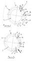
- Figs. A and B in the attached drawings illustrate respectively an exploded representation of a typical aircraft engine propulsion system and a cowling edge seal.
- the engine propulsion system comprises a number of cowling panels and elements and in particular, a nose cowl 100 with side cowls 101, 102 and further cowls 103 associated with the core engine components 104. These cowls 100 to 103 cool and protect the engine core 104.
- the present invention is directed to cowl panels 101, 102, 103 and other cowl or fairing panels which are secured through hinge elements 105 located in a hinge support structure 106 about the core 104 or similar.
- hinge elements such as elements 105 in the hinge support structure 106 which is generally located within a pylon nose cover 107.
- an appropriate robust hinge may not be fully formed such that the panels 101, 102 may become detached in operation.
- This problem is further exacerbated by the use of a "V" groove circumferential seal 108 between the panels 101, 102 and reciprocal parts of the nearest cowl 100 or core 104.
- This "V" groove association in both the leading and trailing edges of the panels 101, 102 provides significant friction association which may retain the panel in position when not under load even when a proper hinge has not been formed between the elements 105 and support structure 106.
- Fig. B provides a cross-sectional detail of such a "V" groove seal arrangement 110.
- a fixed rigid structure on the engine core 104 or casing 100 provides a "V" groove 111 within which an edge 112 of a panel 113 is located to form a seal.
- There is a friction engagement between the edge 112 and the "V" groove 111 which provides a seal but also helps grip the panel 113 in order that it is retained about the core 104 despite the lack of good association between the hinge elements 105 and the support 106.
- a closure panel arrangement for fairings or cowlings or airframes comprising a closure panel secured in use across an opening or a gap from a hinge edge, the closure panel initially retained about the hinge edge upon a mounting edge whereby that panel may pivot about the hinge edge until located and then secured across the opening or gap, the arrangement characterised in that the closure panel is associated with a radial outward bias to ensure only correct alignment between the hinge edge and the mounting edge will be retained upon pivot about the hinge edge for location of the closure panel across the opening or the gap.
- hinge edge and the mounting edge reciprocally co-operate with respective hook clasp and pin means associated in order to allow pivot about the hinge edge.
- closure panel is secured in place by latch means.
- the bias is centrally located between the hinge edge and mounting edge.
- the bias projects from a base structure.
- the bias comprises a torsion spring.
- the torsion spring is in contact with the closure panel through a roller.
- the torsion spring will be displaced through an angle of 90° as it presents bias to the closure panel upon pivot about the hinge edge of the opening or gap.
- the bias may be provided by a foam or rubber insert or an inflated bag or a hydraulic compression spring or a mechanical compression spring.
- the bias is secured to the closure panel and/or other parts to prevent complete fall out of the closure panel when incorrectly aligned.
- the bias acts against a reinforced portion of the closure panel.
- closure panel As indicated above there are a number of situations where it is necessary to secure a closure panel over an aperture, opening or gap particularly with regard to aircraft engines and airframes. These openings or gaps are provided in cowlings and fairings in order to allow access for maintenance and repair and possibly during initial assembly and installation.
- these closure panels will be secured about one side whereby the panel can pivot into position and then be locked by a latch in that position. Unfortunately the latch alone or in association by friction with adjacent panels may retain position even when not properly aligned and secured when there is limited vibration or load stresses placed upon the closure arrangement. However, the panel will fall out when such loads are applied.
- Pivot is generally achieved through a number of hook clasps associated with a pin.
- the pin is in the fixed housing structure whilst the hook clasps are located upon a hinge edge of the closure panel. It is correctly locating these clasp hooks on the pins for alignment and retention which creates difficulties. It will be understood that there is limited access and sight alignment is generally required to achieve the necessary association.
- the hook clasps are intended to engage the pin along a mounting edge of an opening in a fixed structure such as a cowling or fairing, whereby the closure panel can rotate or pivot about the association between hook clasps and pin into a closed position.
- a number of latches will be provided at the opposite side of the closure panel.
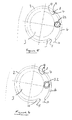
- a closure panel arrangement 1 comprises a substantially fixed fairing or cowling 2, such as that around an engine structure 3, with an opening defined between a hinge edge 4 and a latch edge 5.
- a closure panel 6 extends across the opening in normal use.
- the cowling or fairing 2 will have displaceable closure panels on either side of the engine structure 3 but for clarity only one such closure panel 6 is depicted in figures 1 to 4.
- the closure panel 6 at a mounting end 7 incorporates a number of hook clasps 8. These clasps 8 engage and are retained upon a pin or pins 9 along the hinge edge 4. Thus, the panel 6 can rotate or pivot about that pin 9 in the direction of arrowheads A. The other end of the closure panel 6 is brought into engagement with the mounting end 5.
- a number of latch hooks 10 extend over the latch pins 11 in order to create the tensile or hoop load, as described previously, when the closure panel 6 is correctly aligned and positioned relative to the fixed fairing or cowling 2.
- Figs. 1 and 2 illustrate the present closure panel arrangement when there is correct alignment of the closure panel for robust retention in use, that is to say resistant to operational stress loads and vibration.
- Fig. 1 illustrates the arrangement upon initial assembly with Fig. 2 illustrating the arrangement when closed.
- the hook clasps 8 are correctly associated and aligned with the hinge pins 9 and the latch hooks 10 are correctly aligned with the latch pins 11 then there will be good retention of the closure panel 6 relative to the fairing or cowling 2.
- correct positioning of the hook clasps 8 relative to the hinge pins 9 is difficult due to their position at a recessed location within the hinge edge 4 so that manipulation by sight inspections is difficult into the correct orientation.
- a bias 12 is provided which extends from the relatively stable engine structure 3. This bias 12 is presented radially and outwardly underneath the closure panel 6. Thus, a bias force in the direction of arrowhead B is created by the bias 12. As illustrated, typically this bias 12 takes the form of a torsion spring with a roller 13 at the engagement end with the closure panel 6. The roller 13 limits friction and spreads applied bias load. Typically, the closure panel 6 will also be reinforced at those parts subject to bias load to prevent damage and distortion.
- the pairings of clasp hooks 8 and pins 9 along with latch hooks 10 and latch pins 11 provide radial or hoop retention of the closure panel 6, that is to say retention principally in the direction of arrowhead C with outward displacement resistance of the closure panel 6 dependent upon the hook overlap upon the respective pins 9, 11.
- the clasp hooks 8 are not appropriately and accurately aligned upon the pins 9 then the outward bias provided by the torsion spring 12 will not be resisted and the panel 6 not retained, even though there may be some key fit/friction association between the panel 6 within the opening of the fairing or cowling 2, for example due to V-groove friction grip association.
- the bias 12 ensures that only with appropriate association between the clasp hooks 8 and the pins 9 and subsequently between the latch hooks 10 and pins 11 will the closure panel 6 remain in place.
- the bias 12 ensures that the panel 6 will not remain in place merely due to key fit association between the panel 6 within the gap formed in the fairing 2 when there is limited operational stressing or vibration.
- a roller 13 as indicated above is provided in order to reduce friction and spread bias load applied to the closure panel 6.
- the bias 12 as indicated is normally in the form of a torsion spring. This spring is generally located centrally or midway between the extremities of the opening, that is to say between the hinge edge 4 and the latch edge 5. Normally, to minimise in use the size of the bias spring 12 and roller 13 they will be displaced through an angle of 90° from an initial free uncompressed state to a compressed state with the closure panel 6 in position and retained by latching of the hooks 10 upon the pins 11 as well as retention of the hinge formed between the clasp hooks 8 and the pins 9.
- the bias in terms of the length of the spring is such that in its free state the roller 13 will displace the closure panel 6 to such an extent that the key fit or interference friction between the closure panel 6 and the fairing or cowling 2 is insufficient to retain that panel 6 in position if the hooks 8, 10 and pins 9, 11 are not properly engaged.
- bias and closure panel 6 By appropriate choice of bias and closure panel 6 geometry, it will be understood that the magnitude of bias force typically provided will be easily overcome by displacing the panel 6 in the direction of arrowhead D in order to close the opening with the panel 6 extending across from the hinge edge 4 to the latch edge 5.
- the reaction of the bias 12 when a closing action in the direction of arrowhead D is presented will be to cause the closure panel 6 to rotate about the roller 13 and so fall out of engagement.
- the closure panel 6 will only be retained within the arrangement if there is appropriate association between the hook clasps 8 and pins 9, and subsequently between the latch hooks 10 and the pins 11. If there is no such alignment and retention then the closure panel 6 will continue to fall out of position.
- bias 12 is normally in the form of a torsion spring, it will be appreciated that other arrangements could be provided in which there are more than one bias spring or different forms of bias.
- a compressed foam or rubber insert 22 may be provided in order to create the outward bias necessary to ensure only appropriate association between the clasp hooks 8 with the pins 9 and latch hooks 10 with latch pins 11 ensures appropriate retention of the closure panel 6.
- the insert 22 is deformed under compression as the closure panel 6 is rotated about the hinge end 4 and this compression of the insert 22 creates an outward bias as described previously by shape memory, that is to say a desire to return to its unbiased or free state.
- Fig. 6 illustrates a further embodiment of the present invention in which a bag or bladder is pressurised in order to create the outward bias necessary to ensure that only by correct association between the hook clasps 8 with pins 9 and lock hooks 10 with lock pins 11 will result in retention of the closure panel 6.
- the size and resistance to deformation of the bag 32, as with the insert 22 (figure 5), will be dependent upon the desired bias force and necessary distribution of bias load upon the closure panel 6 to avoid distortion and damage.
- the insert 22 or bag 32 may not require the use of a roller in order to accommodate for the rotational movement of the closure panel 6 but will generally require greater space for accommodation between the engine structure 3 and the closure panel 6.
- An insert 22 or bag 32 may also be more susceptible to environmental temperature changes and pressure variations, particularly when used within an aircraft engine or airframe.
- Fig. 7 illustrates a further embodiment of the present invention in which a mechanical or hydraulic compression spring is utilised in order to provide the bias 42 necessary to ensure only by appropriate combination of clasp hooks with pins and lock pins with lock hooks retains the closure panel relative to the substantially fixed cowling or fairing 2.
- a typical mechanical compression spring comprises a wound helix of sprung steel whilst a hydraulic compression spring comprises a piston within a cylinder whereby an enclosed volume is compressed in order to create a return bias outwardly in accordance with the present invention.
- such a mechanical or hydraulic compression spring generally requires a roller 43 in order to distribute applied bias load as well as accommodate rotation of the closure panel 6 into the desired closed orientation as it pivots and is then retained relative to the fixed cowling or fairings 2.
- the bias in accordance with the present invention will be secured to the relatively stable engine structure or other base structure as an anchor from which it projects. It will also be understood that it is possible to secure the bias to the closure panel where possible with bias contact then made with the stable or base structure as required.
- the closure panel 6 will fall out unless there is appropriate location between the pins and associated hook clasps and lock hooks. In such circumstances in order to prevent damage by falling upon a hard surface the closure panel may be additionally secured through a guard chain or other device including securing the bias both to the base structure and the closure panel to prevent such falling upon hard surfaces. Nevertheless, it will be appreciated that typically the closure panel 6 will be hand manipulated by appropriate personnel such that the panel 6 will be held until maintained by a correct orientation and assembly between the pins and hooks.
- the closure panel will be reinforced to prevent damage due to application of the bias force.
- the bias force may be removed when correct assembly, that is to say engagement between hooks and pins, is confirmed by the closure panel being retained whilst the bias force is operational.
Landscapes
- Engineering & Computer Science (AREA)
- Aviation & Aerospace Engineering (AREA)
- Mechanical Engineering (AREA)
- General Engineering & Computer Science (AREA)
- Superstructure Of Vehicle (AREA)
Applications Claiming Priority (2)
| Application Number | Priority Date | Filing Date | Title |
|---|---|---|---|
| GBGB0320371.8A GB0320371D0 (en) | 2003-08-29 | 2003-08-29 | A closure panel arrangement |
| GB0320371 | 2003-08-29 |
Publications (2)
| Publication Number | Publication Date |
|---|---|
| EP1515006A1 true EP1515006A1 (de) | 2005-03-16 |
| EP1515006B1 EP1515006B1 (de) | 2007-09-26 |
Family
ID=28686646
Family Applications (1)
| Application Number | Title | Priority Date | Filing Date |
|---|---|---|---|
| EP04254615A Expired - Lifetime EP1515006B1 (de) | 2003-08-29 | 2004-07-30 | Anordnung von Verschlusspaneel |
Country Status (4)
| Country | Link |
|---|---|
| US (1) | US7255307B2 (de) |
| EP (1) | EP1515006B1 (de) |
| DE (1) | DE602004009138T2 (de) |
| GB (1) | GB0320371D0 (de) |
Cited By (4)
| Publication number | Priority date | Publication date | Assignee | Title |
|---|---|---|---|---|
| FR2916426A1 (fr) * | 2007-05-22 | 2008-11-28 | Aircelle Sa | Ensemble arriere de nacelle pour turboreacteur. |
| FR2920141A1 (fr) * | 2007-08-20 | 2009-02-27 | Aircelle Sa | Nacelle de turboreacteur, destinee a equiper un aeronef |
| FR2953492A1 (fr) * | 2009-12-09 | 2011-06-10 | Airbus Operations Sas | Nacelle d'aeronef incorporant un dispositif de rapprochement de capots independant du mecanisme de verrouillage |
| FR3007739A1 (fr) * | 2013-07-01 | 2015-01-02 | Aircelle Sa | Dispositif d’assistance pour la manœuvre d’un capot et nacelle de turboreacteur ainsi equipee |
Families Citing this family (28)
| Publication number | Priority date | Publication date | Assignee | Title |
|---|---|---|---|---|
| FR2903665B1 (fr) * | 2006-07-11 | 2008-10-10 | Airbus France Sas | Ensemble moteur pour aeronef comprenant un berceau de support de capot de soufflante monte sur deux elements distincts |
| US20080053060A1 (en) * | 2006-08-29 | 2008-03-06 | Pratt & Whitney Canada Corp. | Bypass lip seal |
| US8015797B2 (en) | 2006-09-21 | 2011-09-13 | Jean-Pierre Lair | Thrust reverser nozzle for a turbofan gas turbine engine |
| US20080258016A1 (en) * | 2007-04-23 | 2008-10-23 | Gukeisen Robert L | Nacelle assembly without lower bi-fi splitter |
| US8091827B2 (en) * | 2007-11-16 | 2012-01-10 | The Nordam Group, Inc. | Thrust reverser door |
| US8052086B2 (en) * | 2007-11-16 | 2011-11-08 | The Nordam Group, Inc. | Thrust reverser door |
| US8172175B2 (en) * | 2007-11-16 | 2012-05-08 | The Nordam Group, Inc. | Pivoting door thrust reverser for a turbofan gas turbine engine |
| US8051639B2 (en) | 2007-11-16 | 2011-11-08 | The Nordam Group, Inc. | Thrust reverser |
| US8052085B2 (en) * | 2007-11-16 | 2011-11-08 | The Nordam Group, Inc. | Thrust reverser for a turbofan gas turbine engine |
| US7735778B2 (en) * | 2007-11-16 | 2010-06-15 | Pratt & Whitney Canada Corp. | Pivoting fairings for a thrust reverser |
| FR2931799B1 (fr) * | 2008-05-30 | 2010-12-24 | Airbus France | Avion a reacteurs arrieres. |
| US8127530B2 (en) | 2008-06-19 | 2012-03-06 | The Nordam Group, Inc. | Thrust reverser for a turbofan gas turbine engine |
| FR2933957B1 (fr) * | 2008-07-18 | 2010-07-30 | Airbus France | Dispositif pour ceinturer une nacelle d'aeronef |
| FR2970513B1 (fr) * | 2011-01-14 | 2015-07-31 | Aircelle Sa | Dispositif de liaison d'un cadre avant a un carter de soufflante |
| US8727275B2 (en) * | 2012-01-27 | 2014-05-20 | Rohr, Inc. | Nacelle |
| US9783315B2 (en) * | 2012-02-24 | 2017-10-10 | Rohr, Inc. | Nacelle with longitudinal translating cowling and rotatable sleeves |
| US9279342B2 (en) | 2012-11-21 | 2016-03-08 | General Electric Company | Turbine casing with service wedge |
| US9845708B2 (en) | 2013-01-29 | 2017-12-19 | United Technologies Corporation | Cowl with rate limited lock |
| US9260281B2 (en) | 2013-03-13 | 2016-02-16 | General Electric Company | Lift efficiency improvement mechanism for turbine casing service wedge |
| EP2969765B1 (de) * | 2013-03-13 | 2018-01-10 | United Technologies Corporation | Hydraulisch betätigte verriegelung für eine triebwerksgondel und betriebsverfahren |
| US10144524B2 (en) * | 2013-06-14 | 2018-12-04 | Rohr, Inc. | Assembly for mounting a turbine engine to a pylon |
| US10173783B2 (en) * | 2016-08-23 | 2019-01-08 | Airbus Helicopters | Rotorcraft with cowling able to rotate and translate relative to the fuselage |
| US10239628B2 (en) * | 2016-09-15 | 2019-03-26 | Rohr, Inc. | Set of latches with identical components for nacelle doors |
| US10906661B2 (en) * | 2018-11-05 | 2021-02-02 | Rohr, Inc. | Nacelle cowl hinge |
| US11548653B2 (en) * | 2019-10-08 | 2023-01-10 | Rohr, Inc. | Support structure for inner cowls of an aircraft propulsion system |
| FR3113485B1 (fr) * | 2020-08-21 | 2022-10-28 | Safran Nacelles | Nacelle pour moteur d’aéronef comportant des capots de soufflante asymétriques |
| FR3138123A1 (fr) * | 2022-07-25 | 2024-01-26 | Arianegroup Sas | Enceinte annulaire d’étage intermédiaire d’un lanceur aérospatial avec ralentisseur de chute |
| FR3142455A1 (fr) * | 2022-11-28 | 2024-05-31 | Airbus Operations | Système de propulsion d’un aéronef comportant une nacelle asymétrique |
Citations (6)
| Publication number | Priority date | Publication date | Assignee | Title |
|---|---|---|---|---|
| US4365775A (en) * | 1980-12-08 | 1982-12-28 | The Boeing Company | Cowl structure alignment and shear device |
| US4679750A (en) * | 1984-06-20 | 1987-07-14 | The Boeing Company | Latch system |
| EP0823373A1 (de) * | 1996-08-08 | 1998-02-11 | The Boeing Company | Selbstzentrierendes Scharnier |
| US5941061A (en) * | 1994-04-18 | 1999-08-24 | Short Brothers Plc | Aircraft propulsive power unit assembly having a leading edge lipskin and intake barrel |
| US6032901A (en) * | 1996-11-28 | 2000-03-07 | Societe Hispano-Suiza | Linkage system for an aircraft turbojet engine |
| US20030102405A1 (en) * | 2001-10-11 | 2003-06-05 | Mcevoy Finbarr | Aircraft propulsive power unit |
Family Cites Families (32)
| Publication number | Priority date | Publication date | Assignee | Title |
|---|---|---|---|---|
| US3347578A (en) * | 1964-11-18 | 1967-10-17 | Boeing Co | Flush-type safety latch |
| FR2291091A1 (fr) * | 1974-11-13 | 1976-06-11 | Snecma | Dispositif de montage sur avion d'un turboreacteur |
| US3952973A (en) * | 1974-12-20 | 1976-04-27 | The Boeing Company | Engine mounting assembly |
| US4044973A (en) * | 1975-12-29 | 1977-08-30 | The Boeing Company | Nacelle assembly and mounting structures for a turbofan jet propulsion engine |
| US4150802A (en) * | 1977-05-31 | 1979-04-24 | The Boeing Company | Aircraft engine installation |
| US4380848A (en) * | 1978-10-19 | 1983-04-26 | Paumellerie Electrique | Stop device for a pivotal door, in particular for an automobile vehicle door |
| FR2501769A1 (fr) * | 1981-03-13 | 1982-09-17 | Paumellerie Electrique | Dispositif d'arret, notamment pour porte de vehicule automobile |
| FR2512486A1 (fr) * | 1981-09-04 | 1983-03-11 | Renault | Dispositif d'equilibrage de hayon de vehicule automobile |
| US4473201A (en) * | 1982-10-29 | 1984-09-25 | The Boeing Company | Canopy-type aircraft cargo door and actuating mechanisms |
| US4528897A (en) * | 1982-11-04 | 1985-07-16 | Energy Cap, Inc. | Chimney cap |
| US4585189A (en) * | 1984-10-22 | 1986-04-29 | Lockheed Corporation | Counterbalanced cowling assembly for a pylon-mounted engine and nacelle therefor |
| US4629146A (en) * | 1985-01-30 | 1986-12-16 | Rohr Industries, Inc. | Hold open rod for hinged section of nacelle system |
| US5046689A (en) * | 1989-04-19 | 1991-09-10 | The Boeing Company | Cowling interlock system |
| US5090640A (en) * | 1990-04-05 | 1992-02-25 | Lucas Western, Inc. | Aircraft door operating mechanism |
| FR2673972B1 (fr) * | 1991-03-12 | 1993-07-23 | Aerospatiale | Porte d'acces, notamment pour nacelle de reacteur d'avion, munie d'un panneau articule a pivotement synchronise. |
| US5251435A (en) * | 1991-10-30 | 1993-10-12 | General Electric Company | Reverser inner cowl with integral bifurcation walls and core cowl |
| US5241325A (en) * | 1991-10-31 | 1993-08-31 | Hewlett-Packard Company | Print cartridge cam actuator linkage |
| US5297017A (en) * | 1991-10-31 | 1994-03-22 | Hewlett-Packard Company | Print cartridge alignment in paper axis |
| JPH0792002B2 (ja) * | 1991-12-26 | 1995-10-09 | ゼネラル・エレクトリック・カンパニイ | ガスタービンエンジン支柱用のダンパアセンブリ |
| GB2266080A (en) * | 1992-04-16 | 1993-10-20 | Rolls Royce Plc | Mounting arrangement for a gas turbine engine. |
| US5350136A (en) * | 1993-05-14 | 1994-09-27 | United Technologies Corporation | Nacelle arrangement |
| IT1272050B (it) * | 1993-11-10 | 1997-06-11 | Olivetti Canon Ind Spa | Dispositivo stampante parallelo con struttura modulare e relativo procedimento di realizzazione. |
| DE4443254C1 (de) * | 1994-11-25 | 1995-12-21 | Francotyp Postalia Gmbh | Anordnung für einen Tintendruckkopf aus einzelnen Tintendruckmodulen |
| US6039287A (en) * | 1996-08-02 | 2000-03-21 | Alliedsignal Inc. | Detachable integral aircraft tailcone and power assembly |
| KR0184565B1 (ko) * | 1996-09-19 | 1999-05-15 | 삼성전자주식회사 | 다중 프린트 헤드가 장착된 잉크 제트 프린터의 인자 방법 |
| FR2771459B1 (fr) * | 1997-11-27 | 2000-02-04 | Aerospatiale | Bielle telescopique d'ouverture d'un capot mobile, notamment de nacelle d'un moteur d'avion |
| FR2771710B1 (fr) * | 1997-12-03 | 2000-02-11 | Aerospatiale | Dispositif d'ouverture commun a deux capots adjacents de nacelle de moteur d'avion |
| US6290332B1 (en) * | 1999-02-18 | 2001-09-18 | Macdermid Acumen, Inc. | Carriage assembly for a large format ink jet print engine |
| US6220546B1 (en) * | 1999-12-29 | 2001-04-24 | The Boeing Company | Aircraft engine and associated aircraft engine cowl |
| AUPQ595700A0 (en) * | 2000-03-02 | 2000-03-23 | Silverbrook Research Pty Ltd | Alignment module for printheads |
| DE10020825B4 (de) * | 2000-04-28 | 2006-08-24 | Eurocopter Deutschland Gmbh | Verfahren und Vorrichtung zum Schliessen einer Tür eines Flugzeuges |
| FR2811716B1 (fr) * | 2000-07-17 | 2002-10-04 | Hurel Dubois Avions | Perfectionnements aux arriere-corps de nacelle, a tuyere commune, de reacteur d'avion |
-
2003
- 2003-08-29 GB GBGB0320371.8A patent/GB0320371D0/en not_active Ceased
-
2004
- 2004-07-30 EP EP04254615A patent/EP1515006B1/de not_active Expired - Lifetime
- 2004-07-30 DE DE602004009138T patent/DE602004009138T2/de not_active Expired - Lifetime
- 2004-08-17 US US10/919,348 patent/US7255307B2/en not_active Expired - Fee Related
Patent Citations (6)
| Publication number | Priority date | Publication date | Assignee | Title |
|---|---|---|---|---|
| US4365775A (en) * | 1980-12-08 | 1982-12-28 | The Boeing Company | Cowl structure alignment and shear device |
| US4679750A (en) * | 1984-06-20 | 1987-07-14 | The Boeing Company | Latch system |
| US5941061A (en) * | 1994-04-18 | 1999-08-24 | Short Brothers Plc | Aircraft propulsive power unit assembly having a leading edge lipskin and intake barrel |
| EP0823373A1 (de) * | 1996-08-08 | 1998-02-11 | The Boeing Company | Selbstzentrierendes Scharnier |
| US6032901A (en) * | 1996-11-28 | 2000-03-07 | Societe Hispano-Suiza | Linkage system for an aircraft turbojet engine |
| US20030102405A1 (en) * | 2001-10-11 | 2003-06-05 | Mcevoy Finbarr | Aircraft propulsive power unit |
Cited By (11)
| Publication number | Priority date | Publication date | Assignee | Title |
|---|---|---|---|---|
| FR2916426A1 (fr) * | 2007-05-22 | 2008-11-28 | Aircelle Sa | Ensemble arriere de nacelle pour turboreacteur. |
| WO2008142242A3 (fr) * | 2007-05-22 | 2009-01-22 | Aircelle Sa | Ensemble arrière de nacelle pour turboréacteur |
| US9003770B2 (en) | 2007-05-22 | 2015-04-14 | Aircelle | Nacelle rear assembly for turbojet engine |
| FR2920141A1 (fr) * | 2007-08-20 | 2009-02-27 | Aircelle Sa | Nacelle de turboreacteur, destinee a equiper un aeronef |
| WO2009027590A1 (fr) * | 2007-08-20 | 2009-03-05 | Aircelle | Nacelle de turboréacteur, destinée à équiper un aéronef |
| US8333343B2 (en) | 2007-08-20 | 2012-12-18 | Aircelle | Jet engine nacelle intended to equip an aircraft |
| FR2953492A1 (fr) * | 2009-12-09 | 2011-06-10 | Airbus Operations Sas | Nacelle d'aeronef incorporant un dispositif de rapprochement de capots independant du mecanisme de verrouillage |
| US8894012B2 (en) | 2009-12-09 | 2014-11-25 | Airbus Operations Sas | Aircraft nacelle incorporating a hood closure device that is independent of the locking mechanism |
| FR3007739A1 (fr) * | 2013-07-01 | 2015-01-02 | Aircelle Sa | Dispositif d’assistance pour la manœuvre d’un capot et nacelle de turboreacteur ainsi equipee |
| WO2015001251A1 (fr) * | 2013-07-01 | 2015-01-08 | Aircelle | Dispositif d'assistance pour la manœuvre d'un capot et nacelle de turboréacteur ainsi équipée |
| CN105452105A (zh) * | 2013-07-01 | 2016-03-30 | 埃尔塞乐公司 | 用于操作罩的辅助装置以及装备有该辅助装置的涡轮喷气发动机机舱 |
Also Published As
| Publication number | Publication date |
|---|---|
| GB0320371D0 (en) | 2003-10-01 |
| DE602004009138T2 (de) | 2008-06-05 |
| US7255307B2 (en) | 2007-08-14 |
| EP1515006B1 (de) | 2007-09-26 |
| DE602004009138D1 (de) | 2007-11-08 |
| US20050056726A1 (en) | 2005-03-17 |
Similar Documents
| Publication | Publication Date | Title |
|---|---|---|
| US7255307B2 (en) | Closure panel arrangement | |
| EP3339181B1 (de) | Vorrichtungen und verfahren zur haubeneinrastanzeige | |
| EP3042845B1 (de) | Scharnierstruktur | |
| EP3670353A1 (de) | Riegel mit scherlasttragfähigkeit | |
| EP1911931A2 (de) | Verfahren und Vorrichtung zur Reparatur einer Bläserausgangsleitschaufel | |
| RU2475418C2 (ru) | Гондола, оснащенная по меньшей мере одним клапаном избыточного давления | |
| EP3372806B1 (de) | Akustikplatte eines turbinenmotors und verfahren zur anordnung der akustikplatte | |
| CN110341969B (zh) | 用于机身安装的动力装置的风扇整流罩的闩锁装置 | |
| EP1988239B1 (de) | Strukturverriegelung mit Doppelfunktion | |
| US20160280384A1 (en) | High visibility latch handle | |
| US7510372B2 (en) | Wedge repair of mechanically retained vanes | |
| EP3736217B1 (de) | Druckentlastungsriegel | |
| EP3326916B1 (de) | Gondelverriegelungsausrichtung | |
| EP3650334B1 (de) | Druckentlastungsanordnung | |
| US10640223B2 (en) | Safety maintenance panel for a thrust reverser | |
| GB2047330A (en) | Closable flap arrangement for an aircraft or a spacecraft | |
| CN211116275U (zh) | 一种发动机短舱结构及航空发动机 | |
| EP3037342B1 (de) | Tür zum schliessen einer öffnung in einer struktur und flugzeug | |
| US11198499B2 (en) | Adjustable door seal | |
| CN214352003U (zh) | 安装中间组件及其保护工具 | |
| EP0475877B1 (de) | Rollenbefestigung für Flugzeugmotorabdeckung | |
| EP3748174B1 (de) | Befestigungsanordnung für gondeldruckentlastungstüren | |
| US6726419B2 (en) | Retention pin redundancy system | |
| EP3647203A1 (de) | Gondelverkleidungsscharnier | |
| CN108071489B (zh) | 冷却护罩 |
Legal Events
| Date | Code | Title | Description |
|---|---|---|---|
| PUAI | Public reference made under article 153(3) epc to a published international application that has entered the european phase |
Free format text: ORIGINAL CODE: 0009012 |
|
| AK | Designated contracting states |
Kind code of ref document: A1 Designated state(s): AT BE BG CH CY CZ DE DK EE ES FI FR GB GR HU IE IT LI LU MC NL PL PT RO SE SI SK TR |
|
| AX | Request for extension of the european patent |
Extension state: AL HR LT LV MK |
|
| 17P | Request for examination filed |
Effective date: 20050303 |
|
| 17Q | First examination report despatched |
Effective date: 20050426 |
|
| AKX | Designation fees paid |
Designated state(s): DE FR GB |
|
| GRAP | Despatch of communication of intention to grant a patent |
Free format text: ORIGINAL CODE: EPIDOSNIGR1 |
|
| GRAS | Grant fee paid |
Free format text: ORIGINAL CODE: EPIDOSNIGR3 |
|
| GRAA | (expected) grant |
Free format text: ORIGINAL CODE: 0009210 |
|
| AK | Designated contracting states |
Kind code of ref document: B1 Designated state(s): DE FR GB |
|
| REG | Reference to a national code |
Ref country code: GB Ref legal event code: FG4D |
|
| REF | Corresponds to: |
Ref document number: 602004009138 Country of ref document: DE Date of ref document: 20071108 Kind code of ref document: P |
|
| ET | Fr: translation filed | ||
| PLBE | No opposition filed within time limit |
Free format text: ORIGINAL CODE: 0009261 |
|
| STAA | Information on the status of an ep patent application or granted ep patent |
Free format text: STATUS: NO OPPOSITION FILED WITHIN TIME LIMIT |
|
| 26N | No opposition filed |
Effective date: 20080627 |
|
| REG | Reference to a national code |
Ref country code: FR Ref legal event code: PLFP Year of fee payment: 12 |
|
| REG | Reference to a national code |
Ref country code: FR Ref legal event code: PLFP Year of fee payment: 13 |
|
| REG | Reference to a national code |
Ref country code: FR Ref legal event code: PLFP Year of fee payment: 14 |
|
| REG | Reference to a national code |
Ref country code: FR Ref legal event code: PLFP Year of fee payment: 15 |
|
| PGFP | Annual fee paid to national office [announced via postgrant information from national office to epo] |
Ref country code: FR Payment date: 20180726 Year of fee payment: 15 Ref country code: DE Payment date: 20180727 Year of fee payment: 15 |
|
| PGFP | Annual fee paid to national office [announced via postgrant information from national office to epo] |
Ref country code: GB Payment date: 20180727 Year of fee payment: 15 |
|
| REG | Reference to a national code |
Ref country code: DE Ref legal event code: R119 Ref document number: 602004009138 Country of ref document: DE |
|
| GBPC | Gb: european patent ceased through non-payment of renewal fee |
Effective date: 20190730 |
|
| PG25 | Lapsed in a contracting state [announced via postgrant information from national office to epo] |
Ref country code: GB Free format text: LAPSE BECAUSE OF NON-PAYMENT OF DUE FEES Effective date: 20190730 Ref country code: DE Free format text: LAPSE BECAUSE OF NON-PAYMENT OF DUE FEES Effective date: 20200201 |
|
| PG25 | Lapsed in a contracting state [announced via postgrant information from national office to epo] |
Ref country code: FR Free format text: LAPSE BECAUSE OF NON-PAYMENT OF DUE FEES Effective date: 20190731 |