EP3042845B1 - Scharnierstruktur - Google Patents
Scharnierstruktur Download PDFInfo
- Publication number
- EP3042845B1 EP3042845B1 EP16150434.5A EP16150434A EP3042845B1 EP 3042845 B1 EP3042845 B1 EP 3042845B1 EP 16150434 A EP16150434 A EP 16150434A EP 3042845 B1 EP3042845 B1 EP 3042845B1
- Authority
- EP
- European Patent Office
- Prior art keywords
- hinge
- pin
- clamp
- retaining mechanism
- door
- Prior art date
- Legal status (The legal status is an assumption and is not a legal conclusion. Google has not performed a legal analysis and makes no representation as to the accuracy of the status listed.)
- Active
Links
Images


Classifications
-
- B—PERFORMING OPERATIONS; TRANSPORTING
- B64—AIRCRAFT; AVIATION; COSMONAUTICS
- B64C—AEROPLANES; HELICOPTERS
- B64C1/00—Fuselages; Constructional features common to fuselages, wings, stabilising surfaces or the like
- B64C1/14—Windows; Doors; Hatch covers or access panels; Surrounding frame structures; Canopies; Windscreens accessories therefor, e.g. pressure sensors, water deflectors, hinges, seals, handles, latches, windscreen wipers
- B64C1/1407—Doors; surrounding frames
- B64C1/1446—Inspection hatches
-
- B—PERFORMING OPERATIONS; TRANSPORTING
- B64—AIRCRAFT; AVIATION; COSMONAUTICS
- B64D—EQUIPMENT FOR FITTING IN OR TO AIRCRAFT; FLIGHT SUITS; PARACHUTES; ARRANGEMENT OR MOUNTING OF POWER PLANTS OR PROPULSION TRANSMISSIONS IN AIRCRAFT
- B64D29/00—Power-plant nacelles, fairings or cowlings
-
- B—PERFORMING OPERATIONS; TRANSPORTING
- B64—AIRCRAFT; AVIATION; COSMONAUTICS
- B64D—EQUIPMENT FOR FITTING IN OR TO AIRCRAFT; FLIGHT SUITS; PARACHUTES; ARRANGEMENT OR MOUNTING OF POWER PLANTS OR PROPULSION TRANSMISSIONS IN AIRCRAFT
- B64D29/00—Power-plant nacelles, fairings or cowlings
- B64D29/06—Attaching of nacelles, fairings or cowlings
-
- B—PERFORMING OPERATIONS; TRANSPORTING
- B64—AIRCRAFT; AVIATION; COSMONAUTICS
- B64D—EQUIPMENT FOR FITTING IN OR TO AIRCRAFT; FLIGHT SUITS; PARACHUTES; ARRANGEMENT OR MOUNTING OF POWER PLANTS OR PROPULSION TRANSMISSIONS IN AIRCRAFT
- B64D29/00—Power-plant nacelles, fairings or cowlings
- B64D29/08—Inspection panels for power plants
-
- E—FIXED CONSTRUCTIONS
- E05—LOCKS; KEYS; WINDOW OR DOOR FITTINGS; SAFES
- E05D—HINGES OR SUSPENSION DEVICES FOR DOORS, WINDOWS OR WINGS
- E05D5/00—Construction of single parts, e.g. the parts for attachment
- E05D5/02—Parts for attachment, e.g. flaps
- E05D5/06—Bent flaps
-
- E—FIXED CONSTRUCTIONS
- E05—LOCKS; KEYS; WINDOW OR DOOR FITTINGS; SAFES
- E05D—HINGES OR SUSPENSION DEVICES FOR DOORS, WINDOWS OR WINGS
- E05D7/00—Hinges or pivots of special construction
- E05D7/10—Hinges or pivots of special construction to allow easy separation or connection of the parts at the hinge axis
- E05D7/1061—Hinges or pivots of special construction to allow easy separation or connection of the parts at the hinge axis in a radial direction
- E05D7/1066—Hinges or pivots of special construction to allow easy separation or connection of the parts at the hinge axis in a radial direction requiring a specific angular position
-
- E—FIXED CONSTRUCTIONS
- E05—LOCKS; KEYS; WINDOW OR DOOR FITTINGS; SAFES
- E05D—HINGES OR SUSPENSION DEVICES FOR DOORS, WINDOWS OR WINGS
- E05D5/00—Construction of single parts, e.g. the parts for attachment
- E05D5/02—Parts for attachment, e.g. flaps
- E05D5/06—Bent flaps
- E05D2005/067—Bent flaps gooseneck shaped
-
- E—FIXED CONSTRUCTIONS
- E05—LOCKS; KEYS; WINDOW OR DOOR FITTINGS; SAFES
- E05Y—INDEXING SCHEME ASSOCIATED WITH SUBCLASSES E05D AND E05F, RELATING TO CONSTRUCTION ELEMENTS, ELECTRIC CONTROL, POWER SUPPLY, POWER SIGNAL OR TRANSMISSION, USER INTERFACES, MOUNTING OR COUPLING, DETAILS, ACCESSORIES, AUXILIARY OPERATIONS NOT OTHERWISE PROVIDED FOR, APPLICATION THEREOF
- E05Y2900/00—Application of doors, windows, wings or fittings thereof
- E05Y2900/50—Application of doors, windows, wings or fittings thereof for vehicles
- E05Y2900/502—Application of doors, windows, wings or fittings thereof for vehicles for aircraft or spacecraft
Definitions
- a hinged door is often supported by a hinge pin which defines the axis of rotation of the door.
- the hinge pin may be removable by sliding it off of the hinge. In some applications, however, there may be an obstruction which impedes the removal of the hinge pin.
- the present invention is directed towards removing a hinged door or panel without removal of the hinge pin.
- US 2 209 659 A discloses a door mounting and hinge construction.
- EP 0140700 A2 discloses a self-aligning hinge.
- FR 2 590 618 A1 discloses a hinge for a motor vehicle or the like.
- GB 1 014 377 A discloses a releasable coupling means for pivotally connecting together two members.
- the invention provides a system configured for an aircraft as set forth in claim 1.
- the hinge is configured as a gooseneck hinge.
- the clamp comprises a through hole that rotatively receives the pin for coupling the clamp and the pin.
- the clamp is configured to removably rotate about the pin when the retaining mechanism is disengaged with respect to the hinge.
- the system further comprises an attachment mechanism to couple the pin to a structure of the aircraft.
- the structure of the aircraft comprises a latch beam on a thrust reverser.
- the system further comprises a thermal blanket that is positioned to physically obscure access to the attachment mechanism.
- the retaining mechanism couples the clamp and the hinge when the retaining mechanism is engaged with respect to the hinge and decouples the clamp and the hinge when the retaining mechanism is disengaged with respect to the hinge.
- connections are set forth between elements in the following description and in the drawings (the contents of which are included in this disclosure by way of reference). It is noted that these connections are general and, unless specified otherwise, may be direct or indirect and that this specification is not intended to be limiting in this respect.
- a coupling between two or more components may refer to a direct connection or an indirect connection.
- An indirect connection may incorporate one or more intervening components.
- Various aspects of the disclosure are directed to a removal or installation of a unit of an aircraft, such as a latch access door or other types of access panels or doors. Opening the latch access door may enable a user (e.g., a technician or a mechanic) access to additional latches that may be used to open or close components on an aircraft, such as a fan cowl or a thrust reverser on an aircraft's nacelle.
- a user e.g., a technician or a mechanic
- additional latches may be used to open or close components on an aircraft, such as a fan cowl or a thrust reverser on an aircraft's nacelle.
- a prior art gooseneck hinge 102 is shown as being coupled to a latch access door 104 via one or more nuts-and-bolts 105.
- One or more attachment mechanisms 106 such as a nut-and-bolt configuration, may be used to couple the hinge 102 to a portion of the aircraft via a hinge/clevis pin 108.
- the pin 108 may define an axis for opening or closing the latch access door 104 via a rotation of the hinge 102 about the pin 108.
- the attachment mechanism 106 may couple the pin 108 to a structure of the aircraft such as the aircraft's engine nacelle, and more particularly to a thrust reverser latch beam.
- access to an attachment mechanism 106 may be obscured by another component, such as a thermal blanket (not shown in FIG. 1 ).
- a thermal blanket not shown in FIG. 1 .
- a user would need to bend out of the way or remove the thermal blanket, which is not ideal.
- FIGS. 2A-2B (collectively referred to as FIG. 2 ), an embodiment of a hinge 202 and the door 104 is shown about the pin 108.
- the hinge 202 may be similar to the hinge 102 of FIG. 1 . However, whereas the hinge 102 may radially encircle or radially encapsulate the pin 108, the hinge 202 may be configured to include a slot 208 such that the pin 108 can reside in a cavity formed via the slot 208.
- a clamp 210 is included.
- the clamp 210 has two parallel legs 252 and 254 and an end 256 connecting the first end of the legs.
- Each of the legs 252 and 254 may be configured with a through hole 228 proximate the second end of the legs 252 and 254 (opposite the first end 256) to allow the clamp 210 to be rotatably coupled to the pin 108.
- the clamp 210 may include, or be coupled to or associated with, a retaining mechanism 216 that may be used to selectively lock the pin 108 into the cavity of the slot as shown in FIG. 2 .
- the retaining mechanism 216 provides a compressive force against the hinge to push the slot 208 onto the pin 108 to prevent the slot 208 from disengaging from the pin 108. At the same time a tension force is created in each of the legs 252, 254 of the clamp 210.
- the clamp 210 and the retaining mechanism 216 may limit wear of the slot 208 and pin 108 by providing a biasing force to keep them together and minimize vibration between them.
- the retaining mechanism 216 includes one or more of a screw, a nut, or a bolt.
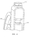
- FIG. 6 illustrates an embodiment of the retaining mechanism 216.
- FIG. 3 illustrates an embodiment of the hinge 202 and the door 104 coupled to a structure 322 (e.g., a latch beam) via the pin 108. Also shown in FIG. 3 is an instance of a thermal blanket 324 that may obscure or make difficult access to attachment mechanisms (e.g., attachment mechanisms 106 of FIG. 1 ) and pin 108 for removal.
- attachment mechanisms e.g., attachment mechanisms 106 of FIG. 1
- FIG. 3 illustrates an embodiment of the hinge 202 and the door 104 coupled to a structure 322 (e.g., a latch beam) via the pin 108.
- a thermal blanket 324 may obscure or make difficult access to attachment mechanisms (e.g., attachment mechanisms 106 of FIG. 1 ) and pin 108 for removal.
- FIG. 2 where the retaining mechanism 216 is shown in an engaged state/condition with respect to the hinge 202
- the retaining mechanism 216 is shown in a disengaged state/condition with respect to the hinge 202 and the clamp 210 is shown as having been
- the hinge 202 may be removed by disengaging the pin 108 from the slot 208 (e.g., in order to remove the door 104) or installed by engaging the pin 108 in the slot 208 (e.g., in order to install the door 104).
- FIG. 4 illustrates an embodiment of the hinge 202 and the door 104 in association with the clamp 210 and the retaining mechanism 216.
- FIG. 4 illustrates the ease of user access to the retaining mechanism 216 and the clamp 210 for removing or installing the door 104.
- the retaining mechanism 216 and the clamp 210 may implement a so-called quick-release feature.
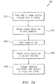
- the method 500 may be used to install a door (e.g., the door 104) to an aircraft structure (e.g., a latch beam).
- a door e.g., the door 104
- an aircraft structure e.g., a latch beam
- a slot (e.g., the slot 208) may be formed in a hinge (e.g., the hinge 202).
- a through hole (e.g., the through hole 228) may be formed in a clamp (e.g., the clamp 210).
- the clamp may be rotated about a pin (e.g., the pin 108) in a first direction in order to create room for the hinge to be seated on the pin.
- a pin e.g., the pin 108
- the hinge may be seated on the pin.
- the pin may be inserted into a hole/cavity formed via a slot (e.g., the slot 208) in the hinge.
- the clamp may be rotated about the pin in a second direction.
- the rotation of the clamp in step 506 may be in an opposite direction to the rotation of step 502, so as to (re)align the clamp with the hinge.
- a retaining mechanism (e.g., the retaining mechanism 216) associated with the clamp may be engaged with respect to the hinge.
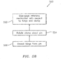
- the method 550 may be used to remove a door (e.g., the door 104) from an aircraft structure (e.g., a latch beam).
- a door e.g., the door 104
- an aircraft structure e.g., a latch beam
- a retaining mechanism e.g., the retaining mechanism 216) associated with the clamp may be disengaged with respect to the hinge.
- the clamp may be rotated about a pin (e.g., the pin 108) to misalign the clamp and the hinge in order to create room for the hinge to be unseated from the pin.
- a pin e.g., the pin 10
- the hinge may be unseated from the pin.
- the removal of the hinge from the pin in step 556 may be achieved using a combination of rotations and/or translations to avoid striking the door or any adjacent structure.
- one or more of the aspects of the method 500 may be combined with one or more aspects of the method 550.
Landscapes
- Engineering & Computer Science (AREA)
- Mechanical Engineering (AREA)
- Aviation & Aerospace Engineering (AREA)
- Hinges (AREA)
Claims (7)
- System, das zum Einbauen und Entfernen einer Verriegelungszugangstür (104) von einem Luftfahrzeug konfiguriert ist, wobei das System Folgendes umfasst:eine Luftfahrzeugzelle, die eine Verriegelungszugangstür (104) umfasst;einen Stift (108); undein Scharnier (202), das mit der Verriegelungszugangstür (104) gekoppelt ist, wobei das Scharnier (202) einen Schlitz (208) umfasst, der eine Vertiefung zum drehbaren Koppeln des Scharniers (202) und des Stifts (108) bildet; und wobei das System ferner Folgendes umfasst:eine Halterung (210), die mit dem Stift (108) gekoppelt ist; undeinen Rückhaltemechanismus (216) an der Halterung (210), der selektiv gegen das Scharnier (202) drückt, um den Stift (108) in der Vertiefung zu halten, wenn der Rückhaltemechanismus (216) in Eingriff steht, und das Scharnier (202) löst, wenn der Rückhaltemechanismus (216) außer Eingriff gebracht ist, wobei der Rückhaltemechanismus (216) mindestens eines aus einer Schraube, einer Mutter oder einem Bolzen umfasst.
- System nach Anspruch 1, wobei das Scharnier (202) als ein Schwanenhalsscharnier konfiguriert ist.
- System nach Anspruch 1 oder 2, wobei die Halterung (210) ein Durchgangsloch (228) umfasst, das den Stift (108) drehbar zum Koppeln der Halterung (210) und des Stifts (108) aufnimmt.
- System nach einem der vorstehenden Ansprüche, wobei die Halterung (210) dazu konfiguriert ist, sich lösbar um den Stift (108) zu drehen, wenn der Rückhaltemechanismus (216) in Bezug auf das Scharnier (202) außer Eingriff gebracht ist.
- System nach einem der vorstehenden Ansprüche, ferner Folgendes umfassend:
einen Befestigungsmechanismus, um den Stift (108) an eine Struktur (322) des Luftfahrzeugs zu koppeln. - System nach Anspruch 5, ferner Folgendes umfassend:
eine thermische Abdeckung, die so angeordnet ist, dass sie den Zugang zum Befestigungsmechanismus verdeckt. - System nach einem der vorstehenden Ansprüche, wobei der Rückhaltemechanismus (216) die Halterung (210) und das Scharnier (202) koppelt, wenn der Rückhaltemechanismus (216) in Bezug auf das Scharnier (202) in Eingriff steht, und die Halterung (210) und das Scharnier (202) entkoppelt, wenn der Rückhaltemechanismus (216) in Bezug auf das Scharnier (202) außer Eingriff gebracht ist.
Applications Claiming Priority (1)
| Application Number | Priority Date | Filing Date | Title |
|---|---|---|---|
| US14/592,593 US9758234B2 (en) | 2015-01-08 | 2015-01-08 | Quick release hinge |
Publications (2)
| Publication Number | Publication Date |
|---|---|
| EP3042845A1 EP3042845A1 (de) | 2016-07-13 |
| EP3042845B1 true EP3042845B1 (de) | 2020-09-02 |
Family
ID=55070899
Family Applications (1)
| Application Number | Title | Priority Date | Filing Date |
|---|---|---|---|
| EP16150434.5A Active EP3042845B1 (de) | 2015-01-08 | 2016-01-07 | Scharnierstruktur |
Country Status (2)
| Country | Link |
|---|---|
| US (1) | US9758234B2 (de) |
| EP (1) | EP3042845B1 (de) |
Families Citing this family (13)
| Publication number | Priority date | Publication date | Assignee | Title |
|---|---|---|---|---|
| CN104884023B (zh) * | 2012-12-11 | 2018-07-03 | 皇家飞利浦有限公司 | 用于将构件与结构枢转地并且可移除地连接的增强铰链和方法 |
| CN105775103B (zh) * | 2014-12-22 | 2020-04-03 | 空中客车简易股份有限公司 | 用于封闭结构上的开口的门和飞行器 |
| DE102015226543A1 (de) * | 2015-12-22 | 2017-06-22 | Rolls-Royce Deutschland Ltd & Co Kg | Triebwerksverkleidung |
| US10173783B2 (en) * | 2016-08-23 | 2019-01-08 | Airbus Helicopters | Rotorcraft with cowling able to rotate and translate relative to the fuselage |
| FR3079000A1 (fr) * | 2018-03-13 | 2019-09-20 | Airbus Operations | Turboreacteur double flux pour un aeronef avec une ouverture equipee d'une charniere avec ferrure en col de cygne |
| US10711646B2 (en) | 2018-07-03 | 2020-07-14 | Rohr, Inc. | Catch assembly for controlling opening of a door |
| US10906661B2 (en) * | 2018-11-05 | 2021-02-02 | Rohr, Inc. | Nacelle cowl hinge |
| CN112173128B (zh) * | 2020-09-25 | 2022-10-28 | 中国直升机设计研究所 | 一种旋翼机铰链门用可抛放撑杆装置 |
| SI26094A (sl) * | 2020-10-12 | 2022-04-29 | Turna D.O.O. | Tečaj vrat pri gospodinjskih aparatih |
| CN112627657A (zh) * | 2020-12-17 | 2021-04-09 | 中航沈飞民用飞机有限责任公司 | 一种以增材制造技术制作的apu舱门铰链接头 |
| US11384660B1 (en) | 2020-12-23 | 2022-07-12 | Rohr, Inc. | Fan cowl failsafe gooseneck assembly |
| EP4067235B1 (de) * | 2021-03-29 | 2024-02-28 | AIRBUS HELICOPTERS DEUTSCHLAND GmbH | Öffnungssystem für eine tür |
| CN116374151A (zh) * | 2023-04-25 | 2023-07-04 | 中国商用飞机有限责任公司 | 一种能够提升舱门开启速度的舱门开启装置 |
Family Cites Families (25)
| Publication number | Priority date | Publication date | Assignee | Title |
|---|---|---|---|---|
| US1646644A (en) | 1925-06-30 | 1927-10-25 | Michael J Economides | Hinge |
| US2209659A (en) | 1937-10-11 | 1940-07-30 | Leon Ottinger | Door mounting and hinge construction |
| US2778053A (en) | 1954-09-13 | 1957-01-22 | Duro Metal Products Co | Separable hinged mounting for motors or the like |
| GB1014377A (en) | 1963-12-19 | 1965-12-22 | William Newman & Sons Ltd | Releasable coupling means for pivotally connecting together two members |
| AU1746870A (en) | 1970-07-10 | 1972-01-13 | Whiton Hardware Manufacturing Co. Pty. Limited | Detachable hinge |
| US4174128A (en) | 1977-07-18 | 1979-11-13 | Caterpillar Tractor Co. | Anti-rattle vehicle door latch mechanism |
| US4799291A (en) | 1983-10-31 | 1989-01-24 | Deere & Company | Self-aligning hinge |
| US4637642A (en) | 1983-12-16 | 1987-01-20 | The Boeing Company | Stowage bin latch assembly |
| FR2590618A1 (fr) | 1985-11-27 | 1987-05-29 | Paumellerie Electrique | Charniere degondable pour portiere de vehicule automobile ou analogue. |
| FR2623553B1 (fr) | 1987-11-20 | 1995-06-30 | Pierre Boismain | Charniere a engagement lateral pour vantail et analogues |
| US4848034A (en) | 1988-05-24 | 1989-07-18 | The Boeing Company | Quick-release latch and access door |
| US5004062A (en) | 1988-09-14 | 1991-04-02 | Paccar Inc. | Vehicle nose pivotal hinge assembly |
| US5826823A (en) | 1996-02-07 | 1998-10-27 | Rohr, Inc. | Actuator and safety lock system for pivoting door thrust reverser for aircraft jet engine |
| FR2768489B1 (fr) * | 1997-09-12 | 1999-11-19 | Eurocopter France | Panneau articule a crochet |
| US6027071A (en) | 1998-08-31 | 2000-02-22 | Lair; Jean-Pierre | Thrust reverser with throat trimming capability |
| US6604355B1 (en) | 2001-08-31 | 2003-08-12 | The Boeing Company | Thrust reverser hook latch system |
| CA2486172C (en) | 2002-05-21 | 2010-11-09 | The Nordam Group, Inc. | Variable area thrust reverser nozzle |
| WO2006136939A2 (en) | 2005-06-24 | 2006-12-28 | Aroplast S.R.L. | Disassemblable hinge and cabinet using it |
| GB0606982D0 (en) | 2006-04-07 | 2006-05-17 | Rolls Royce Plc | Aeroengine thrust reverser |
| US8052085B2 (en) | 2007-11-16 | 2011-11-08 | The Nordam Group, Inc. | Thrust reverser for a turbofan gas turbine engine |
| US8002217B2 (en) | 2007-11-16 | 2011-08-23 | Spirit Aerosystems, Inc. | System for adjustment of thrust reverser pivot door |
| US8091827B2 (en) | 2007-11-16 | 2012-01-10 | The Nordam Group, Inc. | Thrust reverser door |
| US8661667B2 (en) * | 2009-12-15 | 2014-03-04 | United Technologies Corporation | Hinge arm repair |
| US9650917B2 (en) | 2010-09-24 | 2017-05-16 | Short Brothers Plc | Nacelle with hinged cowl doors enabling access to the engine |
| US20120308369A1 (en) * | 2011-05-31 | 2012-12-06 | Mra Systems, Inc. | Laminate thermal insulation blanket for aircraft applications and process therefor |
-
2015
- 2015-01-08 US US14/592,593 patent/US9758234B2/en active Active
-
2016
- 2016-01-07 EP EP16150434.5A patent/EP3042845B1/de active Active
Non-Patent Citations (1)
| Title |
|---|
| None * |
Also Published As
| Publication number | Publication date |
|---|---|
| EP3042845A1 (de) | 2016-07-13 |
| US9758234B2 (en) | 2017-09-12 |
| US20160201371A1 (en) | 2016-07-14 |
Similar Documents
| Publication | Publication Date | Title |
|---|---|---|
| EP3042845B1 (de) | Scharnierstruktur | |
| US9353559B2 (en) | Latching system for securing two components | |
| US10081434B2 (en) | Track mounted hold open rod | |
| US7735261B2 (en) | Self-locking door assembly | |
| EP3943794B1 (de) | Umkehrbare klammer | |
| US9644394B2 (en) | Door handle assembly, sub-assembly and method of installing same | |
| CA2638303C (en) | Rotating disk system for a vehicle door latch assembly | |
| JP2012530649A (ja) | フックおよびレバーを備える航空機用ラッチ | |
| CN101835649A (zh) | 将热交换器安装在形成机动车辆前端板的垂直结构元件上的装置 | |
| US8943864B2 (en) | Proportional torque shaft clutch assembly | |
| JP2002510582A (ja) | 永久結合した遠隔ラッチ機構 | |
| CN101512085A (zh) | 用于操纵在车辆的门或盖板中的锁的装置 | |
| CN110520584B (zh) | 用于开关柜壳体的推杆锁、相应的装置和相应的方法 | |
| CN113227524B (zh) | 用于家具的翻板配件 | |
| US10876328B2 (en) | Door handle assembly for a motor vehicle | |
| US11473357B2 (en) | Hinge for a removable vehicle door | |
| US9650806B2 (en) | Door handle assembly for a motor vehicle | |
| CN105775103B (zh) | 用于封闭结构上的开口的门和飞行器 | |
| KR200388553Y1 (ko) | 천정패널 고정행거 | |
| US12473095B2 (en) | High visibility hook latch | |
| US10683678B2 (en) | Door with door fitting | |
| EP1713992B1 (de) | Anordnung zur befestigung einer schaltsteuerwelle an einer schaltrohrwelle | |
| US11505050B2 (en) | Emergency mechanism for lid kinematic device | |
| EP2586707A1 (de) | Sicherheitsverriegelung für die Klappe einer Flugzeugtriebwerksgondel | |
| KR100892218B1 (ko) | 회동개폐부재의 부착장치 |
Legal Events
| Date | Code | Title | Description |
|---|---|---|---|
| PUAI | Public reference made under article 153(3) epc to a published international application that has entered the european phase |
Free format text: ORIGINAL CODE: 0009012 |
|
| AK | Designated contracting states |
Kind code of ref document: A1 Designated state(s): AL AT BE BG CH CY CZ DE DK EE ES FI FR GB GR HR HU IE IS IT LI LT LU LV MC MK MT NL NO PL PT RO RS SE SI SK SM TR |
|
| AX | Request for extension of the european patent |
Extension state: BA ME |
|
| STAA | Information on the status of an ep patent application or granted ep patent |
Free format text: STATUS: REQUEST FOR EXAMINATION WAS MADE |
|
| 17P | Request for examination filed |
Effective date: 20170113 |
|
| RBV | Designated contracting states (corrected) |
Designated state(s): AL AT BE BG CH CY CZ DE DK EE ES FI FR GB GR HR HU IE IS IT LI LT LU LV MC MK MT NL NO PL PT RO RS SE SI SK SM TR |
|
| STAA | Information on the status of an ep patent application or granted ep patent |
Free format text: STATUS: EXAMINATION IS IN PROGRESS |
|
| 17Q | First examination report despatched |
Effective date: 20170907 |
|
| GRAP | Despatch of communication of intention to grant a patent |
Free format text: ORIGINAL CODE: EPIDOSNIGR1 |
|
| STAA | Information on the status of an ep patent application or granted ep patent |
Free format text: STATUS: GRANT OF PATENT IS INTENDED |
|
| INTG | Intention to grant announced |
Effective date: 20191111 |
|
| RIN1 | Information on inventor provided before grant (corrected) |
Inventor name: HEBER, WILLIAM Inventor name: HARDING, DAVID |
|
| GRAJ | Information related to disapproval of communication of intention to grant by the applicant or resumption of examination proceedings by the epo deleted |
Free format text: ORIGINAL CODE: EPIDOSDIGR1 |
|
| STAA | Information on the status of an ep patent application or granted ep patent |
Free format text: STATUS: EXAMINATION IS IN PROGRESS |
|
| GRAP | Despatch of communication of intention to grant a patent |
Free format text: ORIGINAL CODE: EPIDOSNIGR1 |
|
| STAA | Information on the status of an ep patent application or granted ep patent |
Free format text: STATUS: GRANT OF PATENT IS INTENDED |
|
| INTC | Intention to grant announced (deleted) | ||
| INTG | Intention to grant announced |
Effective date: 20200320 |
|
| GRAS | Grant fee paid |
Free format text: ORIGINAL CODE: EPIDOSNIGR3 |
|
| GRAA | (expected) grant |
Free format text: ORIGINAL CODE: 0009210 |
|
| STAA | Information on the status of an ep patent application or granted ep patent |
Free format text: STATUS: THE PATENT HAS BEEN GRANTED |
|
| AK | Designated contracting states |
Kind code of ref document: B1 Designated state(s): AL AT BE BG CH CY CZ DE DK EE ES FI FR GB GR HR HU IE IS IT LI LT LU LV MC MK MT NL NO PL PT RO RS SE SI SK SM TR |
|
| REG | Reference to a national code |
Ref country code: GB Ref legal event code: FG4D |
|
| REG | Reference to a national code |
Ref country code: AT Ref legal event code: REF Ref document number: 1308528 Country of ref document: AT Kind code of ref document: T Effective date: 20200915 Ref country code: CH Ref legal event code: EP |
|
| REG | Reference to a national code |
Ref country code: DE Ref legal event code: R096 Ref document number: 602016043029 Country of ref document: DE |
|
| REG | Reference to a national code |
Ref country code: IE Ref legal event code: FG4D |
|
| REG | Reference to a national code |
Ref country code: LT Ref legal event code: MG4D |
|
| PG25 | Lapsed in a contracting state [announced via postgrant information from national office to epo] |
Ref country code: FI Free format text: LAPSE BECAUSE OF FAILURE TO SUBMIT A TRANSLATION OF THE DESCRIPTION OR TO PAY THE FEE WITHIN THE PRESCRIBED TIME-LIMIT Effective date: 20200902 Ref country code: GR Free format text: LAPSE BECAUSE OF FAILURE TO SUBMIT A TRANSLATION OF THE DESCRIPTION OR TO PAY THE FEE WITHIN THE PRESCRIBED TIME-LIMIT Effective date: 20201203 Ref country code: NO Free format text: LAPSE BECAUSE OF FAILURE TO SUBMIT A TRANSLATION OF THE DESCRIPTION OR TO PAY THE FEE WITHIN THE PRESCRIBED TIME-LIMIT Effective date: 20201202 Ref country code: HR Free format text: LAPSE BECAUSE OF FAILURE TO SUBMIT A TRANSLATION OF THE DESCRIPTION OR TO PAY THE FEE WITHIN THE PRESCRIBED TIME-LIMIT Effective date: 20200902 Ref country code: BG Free format text: LAPSE BECAUSE OF FAILURE TO SUBMIT A TRANSLATION OF THE DESCRIPTION OR TO PAY THE FEE WITHIN THE PRESCRIBED TIME-LIMIT Effective date: 20201202 Ref country code: SE Free format text: LAPSE BECAUSE OF FAILURE TO SUBMIT A TRANSLATION OF THE DESCRIPTION OR TO PAY THE FEE WITHIN THE PRESCRIBED TIME-LIMIT Effective date: 20200902 Ref country code: LT Free format text: LAPSE BECAUSE OF FAILURE TO SUBMIT A TRANSLATION OF THE DESCRIPTION OR TO PAY THE FEE WITHIN THE PRESCRIBED TIME-LIMIT Effective date: 20200902 |
|
| REG | Reference to a national code |
Ref country code: NL Ref legal event code: MP Effective date: 20200902 |
|
| REG | Reference to a national code |
Ref country code: AT Ref legal event code: MK05 Ref document number: 1308528 Country of ref document: AT Kind code of ref document: T Effective date: 20200902 |
|
| PG25 | Lapsed in a contracting state [announced via postgrant information from national office to epo] |
Ref country code: PL Free format text: LAPSE BECAUSE OF FAILURE TO SUBMIT A TRANSLATION OF THE DESCRIPTION OR TO PAY THE FEE WITHIN THE PRESCRIBED TIME-LIMIT Effective date: 20200902 Ref country code: LV Free format text: LAPSE BECAUSE OF FAILURE TO SUBMIT A TRANSLATION OF THE DESCRIPTION OR TO PAY THE FEE WITHIN THE PRESCRIBED TIME-LIMIT Effective date: 20200902 Ref country code: RS Free format text: LAPSE BECAUSE OF FAILURE TO SUBMIT A TRANSLATION OF THE DESCRIPTION OR TO PAY THE FEE WITHIN THE PRESCRIBED TIME-LIMIT Effective date: 20200902 |
|
| PG25 | Lapsed in a contracting state [announced via postgrant information from national office to epo] |
Ref country code: EE Free format text: LAPSE BECAUSE OF FAILURE TO SUBMIT A TRANSLATION OF THE DESCRIPTION OR TO PAY THE FEE WITHIN THE PRESCRIBED TIME-LIMIT Effective date: 20200902 Ref country code: SM Free format text: LAPSE BECAUSE OF FAILURE TO SUBMIT A TRANSLATION OF THE DESCRIPTION OR TO PAY THE FEE WITHIN THE PRESCRIBED TIME-LIMIT Effective date: 20200902 Ref country code: RO Free format text: LAPSE BECAUSE OF FAILURE TO SUBMIT A TRANSLATION OF THE DESCRIPTION OR TO PAY THE FEE WITHIN THE PRESCRIBED TIME-LIMIT Effective date: 20200902 Ref country code: PT Free format text: LAPSE BECAUSE OF FAILURE TO SUBMIT A TRANSLATION OF THE DESCRIPTION OR TO PAY THE FEE WITHIN THE PRESCRIBED TIME-LIMIT Effective date: 20210104 Ref country code: NL Free format text: LAPSE BECAUSE OF FAILURE TO SUBMIT A TRANSLATION OF THE DESCRIPTION OR TO PAY THE FEE WITHIN THE PRESCRIBED TIME-LIMIT Effective date: 20200902 Ref country code: CZ Free format text: LAPSE BECAUSE OF FAILURE TO SUBMIT A TRANSLATION OF THE DESCRIPTION OR TO PAY THE FEE WITHIN THE PRESCRIBED TIME-LIMIT Effective date: 20200902 |
|
| PG25 | Lapsed in a contracting state [announced via postgrant information from national office to epo] |
Ref country code: AL Free format text: LAPSE BECAUSE OF FAILURE TO SUBMIT A TRANSLATION OF THE DESCRIPTION OR TO PAY THE FEE WITHIN THE PRESCRIBED TIME-LIMIT Effective date: 20200902 Ref country code: AT Free format text: LAPSE BECAUSE OF FAILURE TO SUBMIT A TRANSLATION OF THE DESCRIPTION OR TO PAY THE FEE WITHIN THE PRESCRIBED TIME-LIMIT Effective date: 20200902 Ref country code: ES Free format text: LAPSE BECAUSE OF FAILURE TO SUBMIT A TRANSLATION OF THE DESCRIPTION OR TO PAY THE FEE WITHIN THE PRESCRIBED TIME-LIMIT Effective date: 20200902 Ref country code: IS Free format text: LAPSE BECAUSE OF FAILURE TO SUBMIT A TRANSLATION OF THE DESCRIPTION OR TO PAY THE FEE WITHIN THE PRESCRIBED TIME-LIMIT Effective date: 20210102 |
|
| REG | Reference to a national code |
Ref country code: DE Ref legal event code: R097 Ref document number: 602016043029 Country of ref document: DE |
|
| PG25 | Lapsed in a contracting state [announced via postgrant information from national office to epo] |
Ref country code: SK Free format text: LAPSE BECAUSE OF FAILURE TO SUBMIT A TRANSLATION OF THE DESCRIPTION OR TO PAY THE FEE WITHIN THE PRESCRIBED TIME-LIMIT Effective date: 20200902 |
|
| PLBE | No opposition filed within time limit |
Free format text: ORIGINAL CODE: 0009261 |
|
| STAA | Information on the status of an ep patent application or granted ep patent |
Free format text: STATUS: NO OPPOSITION FILED WITHIN TIME LIMIT |
|
| 26N | No opposition filed |
Effective date: 20210603 |
|
| PG25 | Lapsed in a contracting state [announced via postgrant information from national office to epo] |
Ref country code: SI Free format text: LAPSE BECAUSE OF FAILURE TO SUBMIT A TRANSLATION OF THE DESCRIPTION OR TO PAY THE FEE WITHIN THE PRESCRIBED TIME-LIMIT Effective date: 20200902 Ref country code: DK Free format text: LAPSE BECAUSE OF FAILURE TO SUBMIT A TRANSLATION OF THE DESCRIPTION OR TO PAY THE FEE WITHIN THE PRESCRIBED TIME-LIMIT Effective date: 20200902 Ref country code: MC Free format text: LAPSE BECAUSE OF FAILURE TO SUBMIT A TRANSLATION OF THE DESCRIPTION OR TO PAY THE FEE WITHIN THE PRESCRIBED TIME-LIMIT Effective date: 20200902 |
|
| REG | Reference to a national code |
Ref country code: CH Ref legal event code: PL |
|
| PG25 | Lapsed in a contracting state [announced via postgrant information from national office to epo] |
Ref country code: LU Free format text: LAPSE BECAUSE OF NON-PAYMENT OF DUE FEES Effective date: 20210107 |
|
| REG | Reference to a national code |
Ref country code: BE Ref legal event code: MM Effective date: 20210131 |
|
| PG25 | Lapsed in a contracting state [announced via postgrant information from national office to epo] |
Ref country code: IT Free format text: LAPSE BECAUSE OF FAILURE TO SUBMIT A TRANSLATION OF THE DESCRIPTION OR TO PAY THE FEE WITHIN THE PRESCRIBED TIME-LIMIT Effective date: 20200902 |
|
| PG25 | Lapsed in a contracting state [announced via postgrant information from national office to epo] |
Ref country code: LI Free format text: LAPSE BECAUSE OF NON-PAYMENT OF DUE FEES Effective date: 20210131 Ref country code: CH Free format text: LAPSE BECAUSE OF NON-PAYMENT OF DUE FEES Effective date: 20210131 |
|
| PG25 | Lapsed in a contracting state [announced via postgrant information from national office to epo] |
Ref country code: IE Free format text: LAPSE BECAUSE OF NON-PAYMENT OF DUE FEES Effective date: 20210107 |
|
| PG25 | Lapsed in a contracting state [announced via postgrant information from national office to epo] |
Ref country code: BE Free format text: LAPSE BECAUSE OF NON-PAYMENT OF DUE FEES Effective date: 20210131 |
|
| PG25 | Lapsed in a contracting state [announced via postgrant information from national office to epo] |
Ref country code: HU Free format text: LAPSE BECAUSE OF FAILURE TO SUBMIT A TRANSLATION OF THE DESCRIPTION OR TO PAY THE FEE WITHIN THE PRESCRIBED TIME-LIMIT; INVALID AB INITIO Effective date: 20160107 |
|
| PG25 | Lapsed in a contracting state [announced via postgrant information from national office to epo] |
Ref country code: CY Free format text: LAPSE BECAUSE OF FAILURE TO SUBMIT A TRANSLATION OF THE DESCRIPTION OR TO PAY THE FEE WITHIN THE PRESCRIBED TIME-LIMIT Effective date: 20200902 |
|
| PG25 | Lapsed in a contracting state [announced via postgrant information from national office to epo] |
Ref country code: MK Free format text: LAPSE BECAUSE OF FAILURE TO SUBMIT A TRANSLATION OF THE DESCRIPTION OR TO PAY THE FEE WITHIN THE PRESCRIBED TIME-LIMIT Effective date: 20200902 |
|
| PG25 | Lapsed in a contracting state [announced via postgrant information from national office to epo] |
Ref country code: MT Free format text: LAPSE BECAUSE OF FAILURE TO SUBMIT A TRANSLATION OF THE DESCRIPTION OR TO PAY THE FEE WITHIN THE PRESCRIBED TIME-LIMIT Effective date: 20200902 |
|
| PGFP | Annual fee paid to national office [announced via postgrant information from national office to epo] |
Ref country code: DE Payment date: 20241218 Year of fee payment: 10 |
|
| PG25 | Lapsed in a contracting state [announced via postgrant information from national office to epo] |
Ref country code: TR Free format text: LAPSE BECAUSE OF FAILURE TO SUBMIT A TRANSLATION OF THE DESCRIPTION OR TO PAY THE FEE WITHIN THE PRESCRIBED TIME-LIMIT Effective date: 20200902 |
|
| PGFP | Annual fee paid to national office [announced via postgrant information from national office to epo] |
Ref country code: GB Payment date: 20251219 Year of fee payment: 11 |
|
| PGFP | Annual fee paid to national office [announced via postgrant information from national office to epo] |
Ref country code: FR Payment date: 20251217 Year of fee payment: 11 |
|
| P01 | Opt-out of the competence of the unified patent court (upc) registered |
Free format text: CASE NUMBER: UPC_APP_0016893_3042845/2025 Effective date: 20251210 |