EP1514786A1 - Vehicle steering damper apparatus, and vehicle incorporating same - Google Patents
Vehicle steering damper apparatus, and vehicle incorporating same Download PDFInfo
- Publication number
- EP1514786A1 EP1514786A1 EP04020566A EP04020566A EP1514786A1 EP 1514786 A1 EP1514786 A1 EP 1514786A1 EP 04020566 A EP04020566 A EP 04020566A EP 04020566 A EP04020566 A EP 04020566A EP 1514786 A1 EP1514786 A1 EP 1514786A1
- Authority
- EP
- European Patent Office
- Prior art keywords
- steering
- torque arm
- housing
- damper apparatus
- steering damper
- Prior art date
- Legal status (The legal status is an assumption and is not a legal conclusion. Google has not performed a legal analysis and makes no representation as to the accuracy of the status listed.)
- Granted
Links
Images


Classifications
-
- B—PERFORMING OPERATIONS; TRANSPORTING
- B62—LAND VEHICLES FOR TRAVELLING OTHERWISE THAN ON RAILS
- B62K—CYCLES; CYCLE FRAMES; CYCLE STEERING DEVICES; RIDER-OPERATED TERMINAL CONTROLS SPECIALLY ADAPTED FOR CYCLES; CYCLE AXLE SUSPENSIONS; CYCLE SIDE-CARS, FORECARS, OR THE LIKE
- B62K21/00—Steering devices
- B62K21/08—Steering dampers
Definitions
- the present invention relates to vehicle hydraulic steering damper apparatus suitable for use in a steering system of a two-wheeled vehicle, and to a vehicle incorporating the described apparatus.
- Fig. 9 of the drawings in the present invention disclosure is a reproduction of Figure 2 of Japanese Patent Laid-Open No. 2003-81172, included herein for discussion purposes. However, the reference numerals in Fig. 9 hereof have been changed from the original numbers used in the reference.
- a steering damper 200 is a hydraulic attenuator arranged between a top bridge 201, which is part of a pivotally movable steering structure, and a substantially rigid head portion 203 attached to and located forward of the vehicle body frame 202.
- the steering damper 200 of Figure 9 has a body portion 204 and a lid 205, which coooperate to define a casing. At this time, the body portion 204 and the lid 205 are jointly fastened together.
- a rear portion of the steering damper 200 is connected to a boss 207, which protrudes upwardly on the upper surface of the head portion 203 of the vehicle body frame 202.
- the steering damper 200 is attached to the boss 207 by a bolt 206.
- a steering nut 208 fastens the upper end of a steering shaft 211, located inside a head pipe 209, to the top bridge 201. Also, the steering nut 208 surrounds the lower end of a pivot shaft 212, which is a rotatable shaft of the steering damper 200, and which is fixedly connected to the steering shaft 211. The pivot shaft 212 is also connected to the top bridge 201 via the steering nut 208.
- pivot shaft 212 and the steering shaft 211 are connected to one another, and rotate integrally together via the top bridge 201.
- reference numeral 213 designates a bottom bridge; 214, a fuel tank; and 215, a turning angle sensor.
- the steering damper 200 detects a turning angle of the steering shaft 211 with the turning angle sensor 215,which rotates integrally with the pivot shaft 212.
- the damper 200 is operable to absorb the external force from the road surface by outputting a signal to a control apparatus.
- pivot shaft 212 and the top bridge 201 can be connected together through the use of an adjustment mechanism, such as a coupling arm and a spherical bearing incorporating an eccentric collar.
- an adjustment mechanism such as a coupling arm and a spherical bearing incorporating an eccentric collar.
- a steering damper apparatus to be installed to a vehicle such as a motorcycle has been proposed in which, during pivotal motion of a movable partition wall for partitioning an oil chamber within a housing into two parts, a damping force is generated by circulating hydraulic fluid between these two oil chambers.
- the apparatus comprises a shaft for pivotally supporting the movable partition wall with respect to the housing, while coupling the base of the movable partition wall in a fixed state.
- the housing and shaft arc arranged above the head pipe.
- the rear portion of the housing is housed within a concave portion formed at the front end portion of the fuel tank. See, for example, Japanese Patent Laid-Open No. 2003-104269, with special reference to page 2 and Fig. 2 thereof.
- the steering damper includes the housing, the shaft and the like, and a connected portion between this steering damper and the steering system members are exposed to weathering and to the elements on the outside thereof.
- the steering damper apparatus is arranged to be centered in the front part of the vehicle body above the head pipe. This is one of the most conspicuous places on the vehicle, and the outside appearance of this portion can be considered to be made unattractive by placement of the steering damper in this location.
- the present invention provides a steering damper, for a saddle-type vehicle, which solves some of the above-mentioned problems.
- a steering damper apparatus is capable of adjusting to a change in distance between a pivotally movable steering shaft and the vehicle body side even if the shaft and connected parts are not formed having enhanced precision.
- An advantage of the present invention, in an embodiment having a pivot arm cover and a housing cover, is that it provides a steering damper apparatus having an attractive outside appearance.
- a vehicle in which a pivotally movable steering system member, that allows steering of the vehicle, is operatively connected to a fixed frame member on the vehicle body side.
- a steering damper apparatus including a rotary damper having a pivotally movable shaft, is interposed between the vehicle body side and the steering system member.
- the steering damper apparatus also includes a first torque arm having an inner end which is fixed to the pivot shaft of this rotary damper.
- the first torque arm also has an outer end opposite the inner end, and the steering damper apparatus also includes a second torque arm connected to the outer end of the first torque arm, in such a manner as to be pivotally movable.
- the tip of the second torque arm is installed to one of the vehicle body side and the steering system member, and a damper case of the rotary damper is installed to the other of the vehicle body side and the steering system member.
- the pivot shaft of the rotary damper is interconnected to the vehicle body side or the steering system member via a linking structure including the first torque arm, a connecting pin, and the second torque arm.
- the first torque arm and the second torque arm are made into a V-shaped link, and an angle between those two torque arms is able to be changed in response to road obstacles, whereby a change in distance between the vehicle body side and the steering system member is absorbed.
- the angle between a pair of torque arms is changed. Since only the number of torque arms is increased, structure of the steering system does not become complicated, and it is possible to mimimize any cost increase.
- an improved steering damper apparatus in which during rocking of a movable partition wall for partitioning an oil chamber into two parts within a housing, a damping force is generated by circulating hydraulic fluid between these two oil chambers.
- the steering damper apparatus includes a shaft for rockingly supporting the movable partition wall with respect to the housing while coupling the base of the movable partition wall in a fixed state, characterized in that one end of thc shaft is caused to project outwardly from the housing.
- a torque arm is connected to the projected portion of the shaft.
- the housing is installed to one of the body frame-side member and the steering system-side member.
- a housing cover for covering the housing is installed to one of the body frame-side member and the steering system-side member or the housing.
- the torque arm is installed to the other of the body frame-side member and the steering system-side member.
- a torque arm cover for covering the torque arm is installed to the other of the body frame-side member and the steering system-side member or the arm.
- a steering damper apparatus is, in addition to one specified above, characterized that in at least one of a mating surface between the housing cover and the torque arm cover, there is formed a circular arc surface having the same center as a pivot axis of the steering system-side member.
- a steering damper apparatus is, in addition to one specified above, characterized that the torque arm cover is fastened to the steering system-side member in the neighborhood of an installation area of the steering system-side member of the torque arm, and is restrained on the steering system-side member by a restraint at a portion to be covered by the housing cover.
- the housing and the torque arm are covered with the housing cover and the torque arm cover respectively, the housing and the torque arm, which are members for constituting the steering damper, are not directly exposed to the elements and inclement weather on the outside, and as a result, the outside appearance is attractive, and remains so over time.
- the cover is divided into portions which are installed on members on the body frame side, which is a fixed side, and portions which are installed on members of the steering system-side, which is a movable side, the steering damper, having movable elements, can be covered with a comparatively small cover.
- the housing cover and the torque arm cover move relatively following it.
- at least one of mating surfaces between those both covers is made into a circular arc surface having the same center as a pivot axis, an aspect of laying one cover upon another does not change.
- a clearance between both covers can be maintained constant irrespective of the rocking position of the steering system-side member, and for this reason, the clearance between both covers can be designed to be small.
- the torque arm cover is installed to the steering system-side member by both fasteners and restraints, a secure connection can be realized. Also, in portions to be covered with the housing cover, restraint is performed by suitable restraining structure. Since this is a simple and easy method of connecting these components, installation of the torque arm cover becomes casier, and the outside appearance is also improved.
- Fig. 1 is a side elevational view of a two-wheeled vehicle equipped with a steering damper apparatus according to a selected illustrative embodiment of the present invention.
- Fig. 2 is a perspective view showing an upper central portion of the steering system of the two-wheeled vehicle of Figure 1;
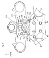
- Fig. 3 is a top plan view showing the upper central portion of the steering system including a steering damper apparatus according to a first embodiment of the invention
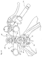
- Fig. 4 is a side detail view in partial section showing the steering damper apparatus of Figure 3;
- Fig. 5 is a cross-sectional detail view of part of the steering damper hereof, showing a connected portion between a pivot shaft, a first torque arm and a second torque arm;
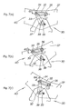
- Fig. 6(a) is a first sequential working view showing the principle of the rotary damper portion of the steering damper apparatus according to an embodiment of the present invention, and Figure 6(b) is a second sequential view thereof;
- Figures 7(a), (b) and (c) are a series of working views showing operation of the linkage of the steering damper apparatus according to an embodiment of the present invention, illustrating the effects of different inputs on the system;
- Fig. 8 is a top plan view showing a front central portion of the motorcycle of Figure 1, illustrating a steering damper apparatus according to a second embodiment of the invention
- Fig. 9 is a reproduction of Fig. 2 of Japanese Patent Laid-Open No. 2003-81172, showing a prior art steering damper in side plan view;
- Fig. 10 is a top plan view of a front end portion of a motorcycle, showing an installed state of the steering damper body according to the first embodiment hereof;
- Fig. 11 is a top plan view similar to Figure 10, showing an installed state of a cover fitting over the steering damper apparatus of Figure 10;
- Fig. 12 is a side view of the steering damper of Figure 11 according to the first embodiment, partially in cross-section, and showing an installed state of the cover of the steering damper apparatus;
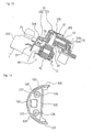
- Fig. 13 is a top plan view showing the housing cover for the steering damper apparatus
- Fig. 14 is a front plan view showing the housing cover of Figure 13;
- Fig. 15 is a side plan view, partially in cross-section, showing the housing cover of Figures 13-14;
- Fig. 16 is a top plan view showing an arm. cover for the steering damper apparatus
- Fig. 17 is a side view, partially in cross-section, showing the arm cover of Figure 16;
- Fig. 18a is a top plan view of a pivotally movable portion of a mororcycle, for explaining an installed state of the arm cover of the steering damper appparatus, and
- Fig. 18b is a cross-sectional detail view taken on line X-X of Fig. 18a.
- Fig. 1 is a side elevational view showing a saddle-type vehicle, which by way of example is a motorcycle 10, equipped with a steering damper apparatus 30 according to a selected illustrative embodiment of the present invention.
- the steering damper apparatus hereof can generally be adapted to be used on any saddle-type vehicle which is pivotally steerable using handlebars.
- the motorcycle 10 includes a main frame 11; a front fork 13 and handlebars 14 which are operatively connected to a steering shaft 42 (to be described in detail later), which is pivotally supported by a head pipe 12 provided at the front end of the main frame 11.
- the motorcycle 10 also includes a front wheel 15, rotatably mounted to the lower end portion of the front fork 13, an engine 16 installed in the lower part of the main frame 11, and a transmission 17 integrally provided in the rear of the engine 16.
- the motorcycle 10 also includes a swing arm 18, pivotally connected to the rear of the main frame 11, for accommodating reciprocal up and down movement of a rear wheel 19, which is rotatably installed on the rear end portion thereof.
- the motorcycle 10 further includes a fuel tank 21, installed on the upper part of the main frame 11.
- the motorcycle includes a driver's seat 22, installed behind the fuel tank 21, and a pillion seat 23, installed behind the driver's seat 22 for accommodating a passenger.
- reference numeral 24 designates a front fender for covering the front wheel 15;
- reference numeral 25 designates an upper cowl;
- reference numeral 26 designates an intake air box.
- Reference numeral 27 designates an exhaust pipe extending backward from the engine 16; and
- reference numeral 28 designates a muffler connected to the exhaust pipe 27.
- the steering system 40 for steering the front wheel 15 includes a pivotally movable portion 29 including a top bridge 37, arranged above and parallel to a bottom bridge, and the handlebars 14, which are respectively affixed to the top bridge.
- the steering system 40 also includes the steering damper apparatus 30 interposed between the pivotally movable portion 29 of the steering system 40 and the body frame 11 (see Fig. 2, Fig. 3), for damping movement of the pivotally movable portion 29.
- the steering damper apparatus 30 is arranged above the head pipe 12 and the handlebars 14, and also absorbs an external force exerted from the road surface during traveling, as needed.
- the steering damper apparatus 30 is constructed such that the lower rear portion of a steering damper housing 31 is fixed to the main frame 11 with bolts 61, 62 (include bolts 63, 64 although not shown).
- the steering damper apparatus 30 includes a first torque arm 33 having an inner (first) end 43 which is fixed to a pivot shaft 32.
- the outer, forward end 44 of the first torque arm 33 is pivotally connected to a first end 45 of a second torque arm 35 via a first pin 34.
- the first pin 34 may comprise a nut and bolt, as shown in Figure 4.
- the tip, or second end 46, of this second torque arm 35 affixed, via a fixing bolt 36, to the top bridge 37 of the steering system 40.
- the first torque arm 33 and the second torque arm 35 are movable via the pivot shaft 32 and the first pin 34. These parts are collectively part of the steering system 40 of the motorcycle 10, and cooperate to form a linkage structure extending between the frame 11 and a pivotally movable part 29 of the steering system 40.
- the steering shaft 42 (Fig. 4) and the pivot shaft 32 of the steering damper apparatus 30, located above the steering shaft are substantially coaxially located, but are not directly connected to one another.
- a rotary damper 51 includes a movable partition wall 52, which is reciprocally pivotally movable within an oil chamber 53, formed in a housing 31 of the steering damper 30.
- a communication passage 57 is formed internally within the steering damper 30, in fluid communication with the oil chamber 53.
- a restriction orifice 59 is formed within an orifice formation member 58 in the communication passage 57, for controlling a flow rate of oil therethrough.
- the rotary damper 51 is installed within the oil chamber 53 formed in the steering damper housing 31, as noted above.
- the steering damper housing 31 is characterized in that it is fixed to a steering damper stay 49, which is connected to the head pipe 12 with bolts 61, 62, 63, 64 and is installed on the vehicle body side, and is fixedly attached thereto.
- Fig. 4 is a side view, partially in cross-section, showing the steering damper apparatus 30.
- the steering damper apparatus 30 provides a structural body in which a control valve driving solenoid 101 is installed in the lower end portion of the steering damper housing 31.
- the first torque arm 33 has an inner (first) end 43 ( Figure 3) disposed adjacent the lower end portion of the steering damper housing 31. This first end 43 of the first torque arm 33 is fixed to the lower end of thc pivot shaft 32, as shown.
- the outer, forwardly disposed second end 44 of this first torque arm 33 is connected to a first end 45 of the second torque arm 35, via the first pin 34.
- the second end 46 of this second torque arm 35 is affixed to the top bridge 37 via the fixing bolt 36 ( Figure 3).
- the steering shaft 42 is located substantially coaxially with the pivot shaft 32 of the steering damper apparatus 30, which is located above the steering shaft 42.
- the steering shaft 42 and the pivot shaft 32 are spaced a short distance apart, and arc not brought into direct contact with one another.
- the steering shaft 42 is constructed to have nuts 92, 93 thereon, above and below a connected portion with the top bridge 37, and to have a nut 94 and a tapered roller bearing 95 on the lower portion thereof.
- a pawl-breaking washer 96 is interposed between the nut 93 and the nut 94 on the steering shaft 42.
- reference numeral 102 designates a main switch key cylinder; 103, a top bridge concave recess; 104, a top bridge-side cover; and 105, a body-side cover.
- the steering damper 30 can be arranged at a low position.
- a link mechanism including the pivot shaft 32; the first torque arm 33; the first pin 34; the second torque arm 35; and the fixing bolt 36 (Fig. 2) is arranged on the upper surface of the top bridge 37, substantially sandwiched between the steering shaft 42 and the main switch key cylinder 102.
- Fig. 5 is a cross-sectional view showing the construction of an optional connected portion between the pivot shaft 32, the first torque arm 33 and the second torque arm 35.
- the first pin 34 interconnects the first and second torque arms 33, 35 by passing through a first spherical bearing 65 on the second torque arm 45 at a juncture extending between the second (forward or outer) end 44 of the first torque arm 33 and the first end 45 of the second torque arm 35.
- the fixing bolt 36 is inserted through a second spherical bearing 66 at the top bridge 37 via the second end 46 of the second torque arm 35.
- connection portion structure is merely illustrative, it is within the scope of the invention to allow for minor changes in connection portion structure, as long as the first pin 34, the fixing bolt 36, the first torque arm 33, and the second torque arm 35 are provided.
- first and second spherical bearings 65, 66 may also be included in this structure.
- the first torque arm 33 includes a bifurcated second end having two spaced apart branch plates 44, 44.
- a connected portion between the first pin 34, the first torque arm 33 and the second torque arm 35 is constructed by connecting the first pin 34, the bifurcated branch plates 44, 44 of first torque arm 33 provided between the first pin 34, the first end of the second torque arm 35, and the nut 91 together, to substantially form a ball-and-socket connection.
- Washers 81, 82 are provided between the bifurcated branch plates 44, 44 and a first spherical bearing 65, composed of a spherical bushing 84, a fitted collar 85 and a snap ring 86.
- the spherical bearing 65 is provided inside the bifurcated branch plates 44, 44 in the axial direction.
- the first end 45 of the second torque arm 35 surrounds and is secured to the first spherical bearing 65.
- a connected portion between the fixing bolt 36 and the top bridge 37 is constructed by connecting together the fixing bolt 36 and the second end 46 of thc second torque ann 35, via a second spherical bearing 66 composed of a spherical bushing 87, a fitted collar 88 surrounding the bushing, and a snap ring 89.
- the second end of the second torque arm 35 substantially surrounds and encloses the second spherical bearing 66, forming a second ball-and-socket connection.
- the steering damper apparatus 30 is capable of absorbing any inclination of longitudinal axes of the connected portions between the top bridge 37 and each torque arm, even if the center 38 of the pivot shaft 32 and the center 48 of the steering shaft incline slightly relative to one another, because the spherical bearings 65, 66 provide dual ball-and-socket joints which adjust to accommodate such inclination.
- the connected portion between the first torque arm 33 and the second torque arm 35, and the connected portion between the second torque arm 35 and the top bridge 37 are each provided with the spherical bearings 65, 66 respectively, whereby a change in angle relative to the inclination of a rotary plane is absorbed by the spherical bearings 65, 66.
- a pitch error (the distance between a center of the damper pivot shaft of the steering damper apparatus 30 and a center of the vehicle body head pipe) is absorbed by the first torque arm 33 and the second torque arm 35, and therefore, members constituting the steering system bearing 40 are capable of securing smooth movement.
- the pivot shaft 32, which is sliding, the first pin 34 and the connected parts are not formed using enhanced dimensional precision techniques, it is still possible to provide a steering damper apparatus 30 capable of accommodating a change in distance between the pivot shaft 32 and the fixing bolt 36 of the second torque arm 35.
- the above-described structure of the steering damper apparatus and the second torque arm automatically adjusts to a change in vertical distance between the pivot shaft 32 and the fixed shaft 42 even if the pivot shaft, which is sliding, and connected parts are not formed having enhanced precision.
- Figs. 6(a) and 6(b) are top working views showing the operation of the steering damper apparatus 30 according to an embodiment of the present invention.
- Fig. 6(a) shows a resting state in which the rotary damper 51 is not operating, and the rotary damper 51 is constructed such that a movable partition wall 52 is mounted to an input shaft 56 within the steering damper housing 31; there is provided an oil chamber 53 filled with oil 71; the interior of this oil chamber 53 is partitioned into a first chamber 54 and a second chamber 55 and the first chamber 54 is caused to communicate to the second chamber 55 through a communication passage 57; and this communication passage 57 is provided with an orifice formation member 58.
- the orifice formation member 58 is a member in which there is provided a restriction orifice 59 for reducing a flow volume of oil which passes through the interior thereof.
- Fig. 6(b) shows a state in which the rotary damper 51 is operating, and for example, when an external force is exerted on the front wheel from the road surface; a force for steering the front wheel to the left is transmitted to the first torque arm 33 via the front fork, the top bridge and the second torque arm (See Fig. 1, 2); and the first torque arm 33 swings as indicated by an arrow a, the movable partition wall 52 swings integrally with the first torque arm 33, and the oil 71 within the second chamber 55 of the rotary damper 51 passes through the communication passage 57 and the orifice formation member 58 to reach the first chamber 54 as indicated by arrows b, c and d in the drawing.
- the steering damper apparatus 30 works to restrain the great rotating force of the input shaft 56 due to the external force.
- Figs. 7(a) to 7(c) are working views showing an operation of the steering damper apparatus 30.
- Fig. 7(a) shows a state before the steering damper apparatus 30 operates, and at this time, the front wheel (See Fig. 1) is in a state for facing the front of the vehicle.
- a resting distance between a center 38 ofthe pivot shaft 32 and a center of the fixing bolt 36 is assumed to be L1
- an angle between a center line of the first torque arm 33 and a center line of the second torque arm 35 is assumed to be ⁇ 2.
- reference numeral 39 designates a center of the vehicle body head pipe, and distance between this center 39 of the vehicle body head pipe and the center 3 of the pivot shaft 32 is a pitch error.
- Fig. 7(b) shows that when the handlebars 14 (See Fig. 1) are steered to the left and the steering damper apparatus 30 operates, and an external force is exerted on the front wheel from the road surface.
- a force for steering the front wheel to the left is transmitted to the first torque arm 33 via the front fork (See Fig. 1), the top bridge 37, and the second torque arm 35.
- the pivot shaft 32 rotates to the left, and the first pin 34 rotates to the left.
- the fixing bolt 36 is made integral with the top bridge 37, the connected portion of the second torque arm 35 with the fixing bolt 36 does not move.
- the inclination of the top bridge 37 has been made larger than the actual one for the sake of simplicity of the description.
- the steering damper apparatus 30 has absorbed the external force to be exerted from the front wheel (see Fig. 1) of the vehicle by the operation of the spherical bearing 65 (see Fig. 5) interposed in the connected portion between the first pin 34, the first torque arm 33 and the second torque arm 35, and a spherical bearing 66 (see Fig. 5) interposed in the connected portion between the second torque arm 35, the fixing bolt 36 and the top bridge 37.
- the inventive steering damper apparatus 30 is capable of accommodating a change in distance between the center 38 of the pivot shaft 32 and the center of the fixing bolt 36 of the second torque arm 35.
- Fig. 7(c) shows that when the handlebars 14 (See Fig. 1) are steered to the right and the steering damper apparatus 30 operates, and an external force is exerted on the front wheel from the road surface.
- a force for steering the front wheel to the right is transmitted to the first torque arm 33 via the front fork (See Fig. 1), the top bridge 37, and the second torque arm 35.
- the pivot shaft 32 rotates to the right although somewhat, and the first pin 34 rotates to the right.
- the fixing bolt 36 is made integral with the top bridge 37, the connected portion of thc second torque arm 35 with the fixing bolt 36 docs not move.
- the inclination of the top bridge 37 has been made larger than the actual one for the sake of simplicity of the description.
- the distance between the pivot shaft 32 and the fixing bolt 36 of the second torque arm 35 is of variable length, within a limited range, because of the first torque arm 33 and the second torque arm 35. Therefore, even if a pitch error occurs with the rotation, in order to absorb it, it is possible to cope with it by a relative change in angle between those two parts: the first torque arm 33 and the second torque arm 35. Therefore, the steering system 40 including the steering damper apparatus 30 becomes capable of securing smooth movement without causing any deformation in the component parts.
- a steering damper apparatus 30 is composed of a steering damper body 107 and a cover 106 for covering the steering damper body 107, and is installed to the vehicle body such that it is located lower than a line L4 for connecting between the lower portion of a meter 80 at the rear end to be arranged forward of the head pipe 12 and the upper portion of the key cylinder 102 at the front end (See Fig. 1).
- the steering damper body 107 absorbs vibrations at a low steering angle area due to road surface disturbance during traveling at high speed by means of a hydraulic shock absorbing mechanism provided therein.
- a hydraulic shock absorbing mechanism provided therein.
- rod type Normally, there are two types: rod type and rotary type.
- the invention described herein uses the rotary type steering damper body because it is excellent in terms of compactncss.
- the steering damper body 107 has, as shown in Fig. 10 and Fig. 12, a housing 31 consisting of a body 31A and a lid 31B; a movable partition wall 52 for partitioning an oil chamber into two parts within the housing 31; a shaft 56 for rockingly supporting the movable partition wall 52 with respect to the housing 31 while coupling the base of the movable partition wall 52 in a fixed state; and a first torque arm 33 to be connected to a projecting portion which projects downwardly from the housing 31 of the shaft 56.
- the housing 31 is installed to a gusset portion of the head pipe 12, which is a member on the body frame side via the steering damper stay 49, and the first torque ann 33 is installed to the top bridge 37, which is a member on the steering system side, by a fixing bolt 36 via the second torque arm 35.
- the steering damper cover 106 is, as shown in Fig. 11 and Fig. 12, composed of: a housing cover 105 for covering substantially a half of the front side of the housing 31; and a torque arm cover 104 for covering the first torque arm 33.
- the housing cover 105 is fixed to the housing 31, which is a member (fixed side member) on the body frame side, and the torque arm cover 104 is fixed to the top bridge 37, which is a mcmber (movable side member) on the steering system side.
- the housing cover 105 has, as shown in Figs. 13 to 15, a front plate portion 122 for covering the front portion of the housing 31 and having an aperture 121 at the center of the lower portion; a pair of left and right side plate portions 123, 123 for covering both sides of left and right of the front portion of the housing 31 respectively; and a upper plate portion 125 for covering the upper portion of the front portion of the housing 31, and is formed by, for example, integral forming through the use of resin material. At two left and right places of the upper plate portion 125, there is formed a concave portion 126, and this concave portion 126 is formed with a bolt insertion hole 127.
- this housing cover 105 is fixed to the housing 31 by the tip of the bolt 128 to be inserted into the bolt insertion hole 127 being screwed into the upper surface of the housing 31.
- the head portion of the bolt 128 is housed within the concave portion 126, and therefore, an apex of the head portion becomes substantially flush with the upper surface without projecting from the upper surface of the housing cover 105.
- the arm cover 104 has, as shown in Fig. 16 and Fig. 17, a front plate portion 70 for covering the front portion of the first torque arm 33 and the second torque ann 35; a pair of left and right side plate portions 71, 71 for covering the side of lower projecting portions of the first torque arm 33, the second torque arm 35 and the shaft 32; and a upper plate portion 73 for covering the upper portions of the first torque arm 33 and the second torque arm 35, and is manufactured by integral forming through the use of, for example, resin material.
- bolt engaging portions 74 having an insertion hole are provided to project toward the front on the left and right sides, and in the rear portion at the lower ends of the left and right side plate portions 71, 71, tongue-shaped portions 75, 75 are formed to project backward. Portions where the tongue-shaped portions 75, 75 are provided are portions which are covered with the housing cover 105 when the torque arm cover 104 is fixed to a regular position with respect to the top bridge 37.
- the torque arm cover 104 is fixed to the top bridge 37 when the left and right tongue-shaped portions 75, 75 are restrained by a U-charactcr-shaped restraining portion 49a which stands on the top bridge 37, a bolt 77 is inserted into the insertion hole in the bolt engaging portion 74, and its tip is screwed into the top bridge 37 (See Fig. 18).
- a circular arc surface 78 On the mating surface with the housing cover 105 at the rear end portion of the side plate portion 71 of the torque arm cover 104, there is formed a circular arc surface 78.
- This circular arc surface 78 is formed so as to have the same center P as the pivot axis of the member of the steering system 40 such as, for example, the top bridge 37 and the handlebars 14 (See Fig. 18) when the arm cover 104 is fixed at a regular position of the top bridge 37.
- the rear end portions of the upper plate portion 73 and the side plate portions 71, 71 of the arm cover 104 are to be inserted inwardly from the aperture 121 of the front plate portion of the housing cover 105 so as to be housed within the housing cover 105 by plane sight as shown also in Fig. 11 when the arm cover 104 is fixed at the regular position of the top bridge 37.
- substantially a half of the front side of the housing 31, particularly the front portion of a mating portion between the body 31a and the lid 31B of the housing 31 is covered with the housing cover 105, and a projecting portion of the shaft 32 for projecting downward from the housing 31, the first torque arm 33 connected to the shaft 32, and the second torque arm 35 for coupling therewith are covered with the torque arm cover 104. Therefore, it is possible to prevent dust and rainwater, which receive wind pressure while the vehicle is traveling, from directly striking against the substantially half of the front side of the housing 31 and the first torque arm 33.
- the housing 31 and the first torque arm 33 which are members for constituting the steering damper body 107, are not exposed to the outside, and the outside appearance is attractive.
- the cover 106 for covering the steering damper body 107 is divided into the housing cover 105 to be installed to a member on the body frame side, which is a fixed side, and the torque arm cover 104, which is a portion to be installed to a member on the steering system side, a movable side, the steering damper 107 having a movable element can be covered with a comparatively small cover.
- the torque arm cover 104 also rocks following it.
- a clearance between both covers 53A and 53B can be set to be small in advance.
- the clearance between the circular arc surface 78 of the side plate portion 71 of the torque arm cover 104 and a wall surface 120 of the front plate portion of the housing cover 105 which stands face to face with the circular arc surface 78 can be set to be small.
- the housing cover 105 has been installed to the body frame-side member and the torque arm cover 104 has been installed to the steering system-side member.
- the housing cover 105 is to be installed to the steering system-side member and the torque arm cover 104 is to be installed to the body frame-side member accordingly.
- the housing cover 105 has been installed to the housing 31, the housing cover 105 may be installed to the head pipe 12 or the steering damper stay 59. Also, the torque arm cover 104 may be also directly installed to the first torque arm 33 in place of the top bridge 37.
- Fig. 8 is a top plan view showing a top central portion of the front of a motorcycle including a steering damper apparatus 230 according to a second embodiment of the invention.
- the steering damper apparatus 230 includes a linkage structure having a single first torque arm 233 with two ends extending outwardly, and dual second torque arms 235, arranged to form a Z-shape.
- the steering damper apparatus 230 of the second embodiment is constructed such that the lower end portion of the steering damper housing 23] is fixed to the main frame 11 with bolts 61, 62, 63, 64.
- first torque arm 233 the central portion of which is fixed to the pivot shaft 232 and each of the other ends 244, 244 of these two first torque arms 233, one ends 245, 245 of two second torque arms 235, 235 are connected via the first pins 234, 234; and tips 246, 246 of these two second torque arms 235, 235 on the opposite side are fixed to the top bridge 237 via fixing bolts 36, 36.
- an installed state of the first torque ann 233 and the second torque arms 235, 235 with the pivot shaft 232 as the center is of Z-shaped link structure.
- the first torque arm 233 and the second torque arms 235, 235 are pivotally movable via the pivot shaft 232 and the first pins 234, 234.
- this second embodiment of the steering damper apparatus 230 may also incorporate the dual ball-and-socket connection structure of the second torque arm 35 shown in Figure 5 for each of the second torque arms 235, 235, as well as the bifurcated end structure at each end of the first torque arm 233, as illustrated in Figure 5.
- the steering damper apparatus 30, 230 according to an embodiment of the present invention has been shown and discussed herein as being disposed above the head pipe and the handlebars, but as regards its installed position, no detailed constrictions are imposed. Also, the steering damper apparatus 30, 230 may bc controlled electronically.
- a steering damper apparatus for a two-wheeled vehicle includes a steering damper housing with a lower end portion fixed to the motorcycle's main frame.
- a first torque arm has a first end fixed to a pivotally movable shaft, and a second end which is connected, via a first pin, to a first end of a second torque arm.
- the second torque arm has a second end bolted to a top bridge on the main frame.
- the first and second torque arms are pivotally movable relative to one another, via the pivot shaft and the first pin.
- the apparatus is capable of accommodating a change in distance between the pivot shaft and the bolt on the second torque arm.
- a two-part cover is provided for the steering damper body, including a housing cover secured to a fixed side thereof, and a torque arm cover secured to a movable side thereof.
Landscapes
- Engineering & Computer Science (AREA)
- Mechanical Engineering (AREA)
- Fluid-Damping Devices (AREA)
Abstract
Description
- The present invention claims priority under 35 USC 119 based on Japanese patent application No. 2003-317244, filed September 9, 2003, and Japanese patent application No. 2003-317575, filed September 9, 2003.
- The present invention relates to vehicle hydraulic steering damper apparatus suitable for use in a steering system of a two-wheeled vehicle, and to a vehicle incorporating the described apparatus.
- Conventionally, a number of steering damper designs are known for use on two-wheeled vehicles. For example, a steering damper arranged above a head pipe provided at a front end of a vehicle body frame has previously been disclosed (See, for example, Japanese Patent Laid-Open No. 2003-81172).
- Fig. 9 of the drawings in the present invention disclosure is a reproduction of Figure 2 of Japanese Patent Laid-Open No. 2003-81172, included herein for discussion purposes. However, the reference numerals in Fig. 9 hereof have been changed from the original numbers used in the reference.
- In the prior art structure depicted in Fig. 9, a
steering damper 200 is a hydraulic attenuator arranged between a top bridge 201, which is part of a pivotally movable steering structure, and a substantiallyrigid head portion 203 attached to and located forward of thevehicle body frame 202. - The
steering damper 200 of Figure 9 has abody portion 204 and alid 205, which coooperate to define a casing. At this time, thebody portion 204 and thelid 205 are jointly fastened together. - A rear portion of the
steering damper 200 is connected to aboss 207, which protrudes upwardly on the upper surface of thehead portion 203 of thevehicle body frame 202. Thesteering damper 200 is attached to theboss 207 by abolt 206. - A
steering nut 208 fastens the upper end of asteering shaft 211, located inside ahead pipe 209, to the top bridge 201. Also, thesteering nut 208 surrounds the lower end of apivot shaft 212, which is a rotatable shaft of thesteering damper 200, and which is fixedly connected to thesteering shaft 211. Thepivot shaft 212 is also connected to the top bridge 201 via thesteering nut 208. - In other words, the
pivot shaft 212 and thesteering shaft 211 are connected to one another, and rotate integrally together via the top bridge 201. - In this respect,
reference numeral 213 designates a bottom bridge; 214, a fuel tank; and 215, a turning angle sensor. - When the vehicle receives an external force from a road surface while it is traveling, the
steering damper 200 detects a turning angle of thesteering shaft 211 with theturning angle sensor 215,which rotates integrally with thepivot shaft 212. Thedamper 200 is operable to absorb the external force from the road surface by outputting a signal to a control apparatus. - In the structure of the
steering damper 200 of the Japanese Patent Laid-Open No. 2003-81172, however, although thepivot shaft 212 is directly fitted in thesteering shaft 211, there is a problem that in order to accurately determine the relative positions of thepivot shaft 212 and thesteering shaft 211, it is necessary to use enhanced precision parts, and thus it is difficult and expensive to manufacture. - Also, the
pivot shaft 212 and the top bridge 201 can be connected together through the use of an adjustment mechanism, such as a coupling arm and a spherical bearing incorporating an eccentric collar. However, there is a problem in that the structure of the spherical bearing incorporating the eccentric collar is complicated, resulting in increased maintenance expenses. - A steering damper apparatus to be installed to a vehicle such as a motorcycle has been proposed in which, during pivotal motion of a movable partition wall for partitioning an oil chamber within a housing into two parts, a damping force is generated by circulating hydraulic fluid between these two oil chambers. The apparatus comprises a shaft for pivotally supporting the movable partition wall with respect to the housing, while coupling the base of the movable partition wall in a fixed state. The housing and shaft arc arranged above the head pipe. The rear portion of the housing is housed within a concave portion formed at the front end portion of the fuel tank. See, for example, Japanese Patent Laid-Open No. 2003-104269, with special reference to page 2 and Fig. 2 thereof.
- In the steering damper apparatus specified in Japanese Patent Laid-Open No. 2003-104269, the steering damper includes the housing, the shaft and the like, and a connected portion between this steering damper and the steering system members are exposed to weathering and to the elements on the outside thereof.
- An additional concern is related to the placement of the damper on the vehicle. The steering damper apparatus is arranged to be centered in the front part of the vehicle body above the head pipe. This is one of the most conspicuous places on the vehicle, and the outside appearance of this portion can be considered to be made unattractive by placement of the steering damper in this location.
- The present invention provides a steering damper, for a saddle-type vehicle, which solves some of the above-mentioned problems. In one embodiment of the present invention, a steering damper apparatus is capable of adjusting to a change in distance between a pivotally movable steering shaft and the vehicle body side even if the shaft and connected parts are not formed having enhanced precision. An advantage of the present invention, in an embodiment having a pivot arm cover and a housing cover, is that it provides a steering damper apparatus having an attractive outside appearance.
- According to a first aspect of the invention, a vehicle is provided in which a pivotally movable steering system member, that allows steering of the vehicle, is operatively connected to a fixed frame member on the vehicle body side. A steering damper apparatus, including a rotary damper having a pivotally movable shaft, is interposed between the vehicle body side and the steering system member.
- The steering damper apparatus according to the first aspect also includes a first torque arm having an inner end which is fixed to the pivot shaft of this rotary damper. The first torque arm also has an outer end opposite the inner end, and the steering damper apparatus also includes a second torque arm connected to the outer end of the first torque arm, in such a manner as to be pivotally movable.
- The tip of the second torque arm is installed to one of the vehicle body side and the steering system member, and a damper case of the rotary damper is installed to the other of the vehicle body side and the steering system member.
- The pivot shaft of the rotary damper is interconnected to the vehicle body side or the steering system member via a linking structure including the first torque arm, a connecting pin, and the second torque arm. The first torque arm and the second torque arm are made into a V-shaped link, and an angle between those two torque arms is able to be changed in response to road obstacles, whereby a change in distance between the vehicle body side and the steering system member is absorbed.
- In the steering damper according to the first aspect of the invention, in order to absorb the change in distance between the vehicle body side and the steering system member, the angle between a pair of torque arms is changed. Since only the number of torque arms is increased, structure of the steering system does not become complicated, and it is possible to mimimize any cost increase.
- in addition, since the angle between the pair of torque arms automatically varies in accordance with the change in distance, no special maintenance is required.
- In order to solve the problem related to the appearance of the steering damper apparatus, according a second aspect of the invention, there is provided an improved steering damper apparatus. The improved steering damper apparatus, in which during rocking of a movable partition wall for partitioning an oil chamber into two parts within a housing, a damping force is generated by circulating hydraulic fluid between these two oil chambers. The steering damper apparatus includes a shaft for rockingly supporting the movable partition wall with respect to the housing while coupling the base of the movable partition wall in a fixed state, characterized in that one end of thc shaft is caused to project outwardly from the housing. A torque arm is connected to the projected portion of the shaft. The housing is installed to one of the body frame-side member and the steering system-side member. A housing cover for covering the housing is installed to one of the body frame-side member and the steering system-side member or the housing. The torque arm is installed to the other of the body frame-side member and the steering system-side member. A torque arm cover for covering the torque arm is installed to the other of the body frame-side member and the steering system-side member or the arm.
- A steering damper apparatus according to another aspect of the invention is, in addition to one specified above, characterized that in at least one of a mating surface between the housing cover and the torque arm cover, there is formed a circular arc surface having the same center as a pivot axis of the steering system-side member.
- A steering damper apparatus according to yet another aspect of the invention is, in addition to one specified above, characterized that the torque arm cover is fastened to the steering system-side member in the neighborhood of an installation area of the steering system-side member of the torque arm, and is restrained on the steering system-side member by a restraint at a portion to be covered by the housing cover.
- According to the invention specified above, since the housing and the torque arm are covered with the housing cover and the torque arm cover respectively, the housing and the torque arm, which are members for constituting the steering damper, are not directly exposed to the elements and inclement weather on the outside, and as a result, the outside appearance is attractive, and remains so over time.
- Also, since the cover is divided into portions which are installed on members on the body frame side, which is a fixed side, and portions which are installed on members of the steering system-side, which is a movable side, the steering damper, having movable elements, can be covered with a comparatively small cover.
- According to the invention specified above, when the steering system-side member rocks with respect to the body frame- side member, the housing cover and the torque arm cover move relatively following it. At this time, since at least one of mating surfaces between those both covers is made into a circular arc surface having the same center as a pivot axis, an aspect of laying one cover upon another does not change. As a result, a clearance between both covers can be maintained constant irrespective of the rocking position of the steering system-side member, and for this reason, the clearance between both covers can be designed to be small.
- According to the invention specified above, since the torque arm cover is installed to the steering system-side member by both fasteners and restraints, a secure connection can be realized. Also, in portions to be covered with the housing cover, restraint is performed by suitable restraining structure. Since this is a simple and easy method of connecting these components, installation of the torque arm cover becomes casier, and the outside appearance is also improved.
- Modes for carrying out the present invention are explained below by reference to a number of selected illustrative embodiments of the present invention. The above-mentioned object, other objects, characteristics and advantages of the present invention will become apparent from a review of the following detailed description, which should be read in conjunction with the accompanying drawings. Throughout the following detailed description and in the drawings, like numbers refer to like parts.
- Fig. 1 is a side elevational view of a two-wheeled vehicle equipped with a steering damper apparatus according to a selected illustrative embodiment of the present invention.
- Fig. 2 is a perspective view showing an upper central portion of the steering system of the two-wheeled vehicle of Figure 1;
- Fig. 3 is a top plan view showing the upper central portion of the steering system including a steering damper apparatus according to a first embodiment of the invention;
- Fig. 4 is a side detail view in partial section showing the steering damper apparatus of Figure 3;
- Fig. 5 is a cross-sectional detail view of part of the steering damper hereof, showing a connected portion between a pivot shaft, a first torque arm and a second torque arm;
- Fig. 6(a) is a first sequential working view showing the principle of the rotary damper portion of the steering damper apparatus according to an embodiment of the present invention, and Figure 6(b) is a second sequential view thereof;
- Figures 7(a), (b) and (c) are a series of working views showing operation of the linkage of the steering damper apparatus according to an embodiment of the present invention, illustrating the effects of different inputs on the system;
- Fig. 8 is a top plan view showing a front central portion of the motorcycle of Figure 1, illustrating a steering damper apparatus according to a second embodiment of the invention;
- Fig. 9 is a reproduction of Fig. 2 of Japanese Patent Laid-Open No. 2003-81172, showing a prior art steering damper in side plan view;
- Fig. 10 is a top plan view of a front end portion of a motorcycle, showing an installed state of the steering damper body according to the first embodiment hereof;
- Fig. 11 is a top plan view similar to Figure 10, showing an installed state of a cover fitting over the steering damper apparatus of Figure 10;
- Fig. 12 is a side view of the steering damper of Figure 11 according to the first embodiment, partially in cross-section, and showing an installed state of the cover of the steering damper apparatus;
- Fig. 13 is a top plan view showing the housing cover for the steering damper apparatus;
- Fig. 14 is a front plan view showing the housing cover of Figure 13;
- Fig. 15 is a side plan view, partially in cross-section, showing the housing cover of Figures 13-14;
- Fig. 16 is a top plan view showing an arm. cover for the steering damper apparatus;
- Fig. 17 is a side view, partially in cross-section, showing the arm cover of Figure 16;
- Fig. 18a is a top plan view of a pivotally movable portion of a mororcycle, for explaining an installed state of the arm cover of the steering damper appparatus, and
- Fig. 18b is a cross-sectional detail view taken on line X-X of Fig. 18a.
- Hereinafter, a number of selected illustrative embodiments for carrying out the present invention will be described, with reference to the accompanying drawings. Specifically, a motorcycle equipped with a steering damper apparatus according to an illustrative embodiment of the present invention will be described. In this respect, relative positional terms such as in front, behind, and left and right, as used in the description, are given from the vantage point of a driver, seated on the motorcyle and facing forward thereon.
- Fig. 1 is a side elevational view showing a saddle-type vehicle, which by way of example is a
motorcycle 10, equipped with asteering damper apparatus 30 according to a selected illustrative embodiment of the present invention. The steering damper apparatus hereof can generally be adapted to be used on any saddle-type vehicle which is pivotally steerable using handlebars. - The
motorcycle 10 includes amain frame 11; afront fork 13 andhandlebars 14 which are operatively connected to a steering shaft 42 (to be described in detail later), which is pivotally supported by ahead pipe 12 provided at the front end of themain frame 11. Themotorcycle 10 also includes a front wheel 15, rotatably mounted to the lower end portion of thefront fork 13, anengine 16 installed in the lower part of themain frame 11, and atransmission 17 integrally provided in the rear of theengine 16. - The
motorcycle 10 also includes a swing arm 18, pivotally connected to the rear of themain frame 11, for accommodating reciprocal up and down movement of a rear wheel 19, which is rotatably installed on the rear end portion thereof. Themotorcycle 10 further includes afuel tank 21, installed on the upper part of themain frame 11. - Still further, the motorcycle includes a driver's
seat 22, installed behind thefuel tank 21, and apillion seat 23, installed behind the driver'sseat 22 for accommodating a passenger. Here,reference numeral 24 designates a front fender for covering the front wheel 15;reference numeral 25 designates an upper cowl; andreference numeral 26 designates an intake air box.Reference numeral 27 designates an exhaust pipe extending backward from theengine 16; andreference numeral 28 designates a muffler connected to theexhaust pipe 27. - Referring also to Figures 2-4 as well as Figure 1, the
steering system 40 for steering the front wheel 15 includes a pivotallymovable portion 29 including atop bridge 37, arranged above and parallel to a bottom bridge, and thehandlebars 14, which are respectively affixed to the top bridge. - The
steering system 40 also includes thesteering damper apparatus 30 interposed between the pivotallymovable portion 29 of thesteering system 40 and the body frame 11 (see Fig. 2, Fig. 3), for damping movement of the pivotallymovable portion 29. The steeringdamper apparatus 30 is arranged above thehead pipe 12 and thehandlebars 14, and also absorbs an external force exerted from the road surface during traveling, as needed. - With continued reference to FIGS. 2 and 3, wherein an arrow indicates the front of the
motorcycle 10, a central front-end portion of a two-wheeled vehicle, according to an illustrative embodiment of the present invention, is shown. The steeringdamper apparatus 30 is constructed such that the lower rear portion of asteering damper housing 31 is fixed to themain frame 11 withbolts 61, 62 (includebolts - The steering
damper apparatus 30 includes afirst torque arm 33 having an inner (first) end 43 which is fixed to apivot shaft 32. The outer, forward end 44 of thefirst torque arm 33 is pivotally connected to afirst end 45 of asecond torque arm 35 via afirst pin 34. (Thefirst pin 34 may comprise a nut and bolt, as shown in Figure 4.) The tip, orsecond end 46, of thissecond torque arm 35 affixed, via a fixingbolt 36, to thetop bridge 37 of thesteering system 40. - The
first torque arm 33 and thesecond torque arm 35 are movable via thepivot shaft 32 and thefirst pin 34. These parts are collectively part of thesteering system 40 of themotorcycle 10, and cooperate to form a linkage structure extending between theframe 11 and a pivotallymovable part 29 of thesteering system 40. - In this respect, the steering shaft 42 (Fig. 4) and the
pivot shaft 32 of thesteering damper apparatus 30, located above the steering shaft, are substantially coaxially located, but are not directly connected to one another. - Referring now to Figures 3 and 6, a
rotary damper 51 includes amovable partition wall 52, which is reciprocally pivotally movable within anoil chamber 53, formed in ahousing 31 of thesteering damper 30. Acommunication passage 57 is formed internally within the steeringdamper 30, in fluid communication with theoil chamber 53. When thepartition wall 52 is moved in theoil chamber 53, hydraulic oil from theoil chamber 53 is forced through thecommunication passage 57. Arestriction orifice 59 is formed within anorifice formation member 58 in thecommunication passage 57, for controlling a flow rate of oil therethrough. - The
rotary damper 51 is installed within theoil chamber 53 formed in thesteering damper housing 31, as noted above. Thesteering damper housing 31 is characterized in that it is fixed to asteering damper stay 49, which is connected to thehead pipe 12 withbolts - Fig. 4 is a side view, partially in cross-section, showing the
steering damper apparatus 30. The steeringdamper apparatus 30 provides a structural body in which a controlvalve driving solenoid 101 is installed in the lower end portion of thesteering damper housing 31. Thefirst torque arm 33 has an inner (first) end 43 (Figure 3) disposed adjacent the lower end portion of thesteering damper housing 31. Thisfirst end 43 of thefirst torque arm 33 is fixed to the lower end ofthc pivot shaft 32, as shown. - The outer, forwardly disposed
second end 44 of thisfirst torque arm 33 is connected to afirst end 45 of thesecond torque arm 35, via thefirst pin 34. Thesecond end 46 of thissecond torque arm 35 is affixed to thetop bridge 37 via the fixing bolt 36 (Figure 3). - In this case, the steering
shaft 42 is located substantially coaxially with thepivot shaft 32 of thesteering damper apparatus 30, which is located above the steeringshaft 42. As seen in Figure 4, the steeringshaft 42 and thepivot shaft 32 are spaced a short distance apart, and arc not brought into direct contact with one another. - Also, the steering
shaft 42 is constructed to havenuts top bridge 37, and to have anut 94 and atapered roller bearing 95 on the lower portion thereof. A pawl-breakingwasher 96 is interposed between thenut 93 and thenut 94 on the steeringshaft 42. - In this respect,
reference numeral 102 designates a main switch key cylinder; 103, a top bridge concave recess; 104, a top bridge-side cover; and 105, a body-side cover. - By providing the top bridge
concave recess 103 below thefirst pin 34, the lower end of thefirst pin 34 becomes difficult to abut on thetop bridge 37, and thesteering damper 30 can be arranged at a low position. - A link mechanism including the
pivot shaft 32; thefirst torque arm 33; thefirst pin 34; thesecond torque arm 35; and the fixing bolt 36 (Fig. 2) is arranged on the upper surface of thetop bridge 37, substantially sandwiched between the steeringshaft 42 and the main switchkey cylinder 102. - Fig. 5 is a cross-sectional view showing the construction of an optional connected portion between the
pivot shaft 32, thefirst torque arm 33 and thesecond torque arm 35. In the embodiment of Figure 5, thefirst pin 34 interconnects the first andsecond torque arms spherical bearing 65 on thesecond torque arm 45 at a juncture extending between the second (forward or outer) end 44 of thefirst torque arm 33 and thefirst end 45 of thesecond torque arm 35. - Also, in the embodiment of Figure 5, the fixing
bolt 36 is inserted through a secondspherical bearing 66 at thetop bridge 37 via thesecond end 46 of thesecond torque arm 35. - Since each connected portion of this figure is merely illustrative, it is within the scope of the invention to allow for minor changes in connection portion structure, as long as the
first pin 34, the fixingbolt 36, thefirst torque arm 33, and thesecond torque arm 35 are provided. Optionally, the first and secondspherical bearings - To explain in further detail, in the embodiment depicted in Figure 5, the
first torque arm 33 includes a bifurcated second end having two spaced apartbranch plates first pin 34, thefirst torque arm 33 and thesecond torque arm 35 is constructed by connecting thefirst pin 34, thebifurcated branch plates first torque arm 33 provided between thefirst pin 34, the first end of thesecond torque arm 35, and thenut 91 together, to substantially form a ball-and-socket connection.Washers bifurcated branch plates spherical bearing 65, composed of aspherical bushing 84, a fittedcollar 85 and asnap ring 86. Thespherical bearing 65 is provided inside thebifurcated branch plates first end 45 of thesecond torque arm 35 surrounds and is secured to the firstspherical bearing 65. - On the other hand, a connected portion between the fixing
bolt 36 and thetop bridge 37 is constructed by connecting together the fixingbolt 36 and thesecond end 46 of thcsecond torque ann 35, via a secondspherical bearing 66 composed of aspherical bushing 87, a fittedcollar 88 surrounding the bushing, and asnap ring 89. The second end of thesecond torque arm 35 substantially surrounds and encloses the secondspherical bearing 66, forming a second ball-and-socket connection. - Thereby, the steering
damper apparatus 30 is capable of absorbing any inclination of longitudinal axes of the connected portions between thetop bridge 37 and each torque arm, even if thecenter 38 of thepivot shaft 32 and thecenter 48 of the steering shaft incline slightly relative to one another, because thespherical bearings - As described above, the connected portion between the
first torque arm 33 and thesecond torque arm 35, and the connected portion between thesecond torque arm 35 and thetop bridge 37 are each provided with thespherical bearings spherical bearings steering damper apparatus 30 and a center of the vehicle body head pipe) is absorbed by thefirst torque arm 33 and thesecond torque arm 35, and therefore, members constituting the steering system bearing 40 are capable of securing smooth movement. - Therefore, even if the
pivot shaft 32, which is sliding, thefirst pin 34 and the connected parts are not formed using enhanced dimensional precision techniques, it is still possible to provide asteering damper apparatus 30 capable of accommodating a change in distance between thepivot shaft 32 and the fixingbolt 36 of thesecond torque arm 35. In addition, the above-described structure of the steering damper apparatus and the second torque arm automatically adjusts to a change in vertical distance between thepivot shaft 32 and the fixedshaft 42 even if the pivot shaft, which is sliding, and connected parts are not formed having enhanced precision. - Figs. 6(a) and 6(b) are top working views showing the operation of the
steering damper apparatus 30 according to an embodiment of the present invention. - Fig. 6(a) shows a resting state in which the
rotary damper 51 is not operating, and therotary damper 51 is constructed such that amovable partition wall 52 is mounted to aninput shaft 56 within thesteering damper housing 31; there is provided anoil chamber 53 filled withoil 71; the interior of thisoil chamber 53 is partitioned into afirst chamber 54 and asecond chamber 55 and thefirst chamber 54 is caused to communicate to thesecond chamber 55 through acommunication passage 57; and thiscommunication passage 57 is provided with anorifice formation member 58. - The
orifice formation member 58 is a member in which there is provided arestriction orifice 59 for reducing a flow volume of oil which passes through the interior thereof. - Fig. 6(b) shows a state in which the
rotary damper 51 is operating, and for example, when an external force is exerted on the front wheel from the road surface; a force for steering the front wheel to the left is transmitted to thefirst torque arm 33 via the front fork, the top bridge and the second torque arm (See Fig. 1, 2); and thefirst torque arm 33 swings as indicated by an arrow a, themovable partition wall 52 swings integrally with thefirst torque arm 33, and theoil 71 within thesecond chamber 55 of therotary damper 51 passes through thecommunication passage 57 and theorifice formation member 58 to reach thefirst chamber 54 as indicated by arrows b, c and d in the drawing. - At this time, in the
rotary damper 51, since the flow rate of theoil 71 is reduced by theorifice 59 to be installed midway in the course of thecommunication passage 57, resistance to flow of the oil occurs, so that there works a force which tends to swing themovable partition wall 52 from thesecond chambcr 55 side toward thefirst chamber 54 side conversely. Thus, in order for theinput shaft 56 to rotate in the direction indicated by the arrow a, a great rotating force is required. Accordingly, the steeringdamper apparatus 30 according to an embodiment of the present invention works to restrain the great rotating force of theinput shaft 56 due to the external force. - Figs. 7(a) to 7(c) are working views showing an operation of the
steering damper apparatus 30. - Fig. 7(a) shows a state before the
steering damper apparatus 30 operates, and at this time, the front wheel (See Fig. 1) is in a state for facing the front of the vehicle. A resting distance between acenter 38 ofthepivot shaft 32 and a center of the fixingbolt 36 is assumed to be L1, and an angle between a center line of thefirst torque arm 33 and a center line of thesecond torque arm 35 is assumed to be 2. - Also,
reference numeral 39 designates a center of the vehicle body head pipe, and distance between thiscenter 39 of the vehicle body head pipe and the center 3 of thepivot shaft 32 is a pitch error. - Fig. 7(b) shows that when the handlebars 14 (See Fig. 1) are steered to the left and the
steering damper apparatus 30 operates, and an external force is exerted on the front wheel from the road surface. In this case, a force for steering the front wheel to the left is transmitted to thefirst torque arm 33 via the front fork (See Fig. 1), thetop bridge 37, and thesecond torque arm 35. Thepivot shaft 32 rotates to the left, and thefirst pin 34 rotates to the left. Since, however, the fixingbolt 36 is made integral with thetop bridge 37, the connected portion of thesecond torque arm 35 with the fixingbolt 36 does not move. However, the inclination of thetop bridge 37 has been made larger than the actual one for the sake of simplicity of the description. - As a result, distance L2 between the
center 38 of thepivot shaft 32 and the center of the fixingbolt 36 becomes shelter than L1 of Fig. 7(a), and an angle 3 between the center line of thefirst torque arm 33 and the center line of thesecond torque arm 35 becomes smaller than 92 of Fig. 7(a). - This results from the fact that although the
center 38 of thepivot shaft 32 and thecenter 39 of the vehicle body head pipe deviate by the operation of thesteering dampcr apparatus 30, the steeringdamper apparatus 30 has absorbed the external force to be exerted from the front wheel (see Fig. 1) of the vehicle by the operation of the spherical bearing 65 (see Fig. 5) interposed in the connected portion between thefirst pin 34, thefirst torque arm 33 and thesecond torque arm 35, and a spherical bearing 66 (see Fig. 5) interposed in the connected portion between thesecond torque arm 35, the fixingbolt 36 and thetop bridge 37. - An external force is exerted on the front wheel from the road surface during traveling of the vehicle. As a result, a force for steering the front wheel to the left is transmitted to the
first torque arm 33 via the front fork (See Fig. 1), thetop bridge 37 and thesecond torque arm 35. Even if thepivot shaft 32 rotates to the left although somewhat, and even if the dimensional precision of thepivot shaft 32, which is sliding, thefirst pin 34 and the connected parts arc not be enhanced, the inventivesteering damper apparatus 30 is capable of accommodating a change in distance between thecenter 38 of thepivot shaft 32 and the center of the fixingbolt 36 of thesecond torque arm 35. - Fig. 7(c) shows that when the handlebars 14 (See Fig. 1) are steered to the right and the
steering damper apparatus 30 operates, and an external force is exerted on the front wheel from the road surface. In this case, a force for steering the front wheel to the right is transmitted to thefirst torque arm 33 via the front fork (See Fig. 1), thetop bridge 37, and thesecond torque arm 35. Thepivot shaft 32 rotates to the right although somewhat, and thefirst pin 34 rotates to the right. Since, however, the fixingbolt 36 is made integral with thetop bridge 37, the connected portion of thcsecond torque arm 35 with the fixingbolt 36 docs not move. However, the inclination of thetop bridge 37 has been made larger than the actual one for the sake of simplicity of the description. - As a result, distance L3 between the
center 38 of thepivot shaft 32 and the center of the fixingbolt 36 becomes longer than L1 of Fig. 7(a), and anangle 04 between the center line of thefirst torque arm 33 and the center line of thesecond torque arm 35 becomes larger than 62 of Fig. 7(a). - An external force is exerted on the front wheel from the road surface during traveling of the vehicle. As a result, a force for steering the front wheel to the right is transmitted to the
first torque arm 33 via the front fork (See Fig. 1), thetop bridge 37 and thesecond torque arm 35. Even if thepivot shaft 32 rotates to the right although somewhat, and even if the dimensional precision of thepivot shaft 32, which is sliding, thefirst pin 34 and the connected parts are not be enhanced, it is possible to providesteering damper apparatus 30 that is capable of accommodating a change in distance between thecenter 38 of thepivot shaft 32 and the center of the fixingbolt 36 of thesecond torque arm 35, - From the foregoing, it can be seen that the distance between the
pivot shaft 32 and the fixingbolt 36 of thesecond torque arm 35 is of variable length, within a limited range, because of thefirst torque arm 33 and thesecond torque arm 35. Therefore, even if a pitch error occurs with the rotation, in order to absorb it, it is possible to cope with it by a relative change in angle between those two parts: thefirst torque arm 33 and thesecond torque arm 35. Therefore, thesteering system 40 including thesteering damper apparatus 30 becomes capable of securing smooth movement without causing any deformation in the component parts. - As shown also in Fig. 12, a
steering damper apparatus 30 is composed of asteering damper body 107 and acover 106 for covering thesteering damper body 107, and is installed to the vehicle body such that it is located lower than a line L4 for connecting between the lower portion of ameter 80 at the rear end to be arranged forward of thehead pipe 12 and the upper portion of thekey cylinder 102 at the front end (See Fig. 1). - The
steering damper body 107 absorbs vibrations at a low steering angle area due to road surface disturbance during traveling at high speed by means of a hydraulic shock absorbing mechanism provided therein. Normally, there are two types: rod type and rotary type. However, the invention described herein uses the rotary type steering damper body because it is excellent in terms of compactncss. - The
steering damper body 107 has, as shown in Fig. 10 and Fig. 12, ahousing 31 consisting of abody 31A and a lid 31B; amovable partition wall 52 for partitioning an oil chamber into two parts within thehousing 31; ashaft 56 for rockingly supporting themovable partition wall 52 with respect to thehousing 31 while coupling the base of themovable partition wall 52 in a fixed state; and afirst torque arm 33 to be connected to a projecting portion which projects downwardly from thehousing 31 of theshaft 56. - The
housing 31 is installed to a gusset portion of thehead pipe 12, which is a member on the body frame side via thesteering damper stay 49, and thefirst torque ann 33 is installed to thetop bridge 37, which is a member on the steering system side, by a fixingbolt 36 via thesecond torque arm 35. - Thus, in this
steering damper body 107, when thehandlebars 14 are steered to the left or right, thetop bridge 37 rotates integrally with thehandlebars 14, and the movement is transmitted to theshaft 32 via thesecond torque arm 35 and thefirst torque arm 33 to rotate theshaft 32 and themovable partition wall 52 in a predetermined direction. With the rotation, capacity of the twooil chambers housing 31 changes respectively. At this time, hydraulic fluid moves within theoil passage 57 for communicating between both oil chambers, 54, 55 and passage resistance of this hydraulic fluid is exerted on thehandlebars 14 as a resistance force during rotation. As a result, runout and vibrations of thehandlebars 14 arc to be absorbed. - The steering
damper cover 106 is, as shown in Fig. 11 and Fig. 12, composed of: ahousing cover 105 for covering substantially a half of the front side of thehousing 31; and atorque arm cover 104 for covering thefirst torque arm 33. Thehousing cover 105 is fixed to thehousing 31, which is a member (fixed side member) on the body frame side, and thetorque arm cover 104 is fixed to thetop bridge 37, which is a mcmber (movable side member) on the steering system side. - The
housing cover 105 has, as shown in Figs. 13 to 15, afront plate portion 122 for covering the front portion of thehousing 31 and having anaperture 121 at the center of the lower portion; a pair of left and rightside plate portions housing 31 respectively; and aupper plate portion 125 for covering the upper portion of the front portion of thehousing 31, and is formed by, for example, integral forming through the use of resin material. At two left and right places of theupper plate portion 125, there is formed aconcave portion 126, and thisconcave portion 126 is formed with abolt insertion hole 127. Thus, thishousing cover 105 is fixed to thehousing 31 by the tip of thebolt 128 to be inserted into thebolt insertion hole 127 being screwed into the upper surface of thehousing 31. In this respect, when thehousing cover 105 is fixed to thehousing 31 by thebolt 128, the head portion of thebolt 128 is housed within theconcave portion 126, and therefore, an apex of the head portion becomes substantially flush with the upper surface without projecting from the upper surface of thehousing cover 105. - The
arm cover 104 has, as shown in Fig. 16 and Fig. 17, afront plate portion 70 for covering the front portion of thefirst torque arm 33 and thesecond torque ann 35; a pair of left and rightside plate portions first torque arm 33, thesecond torque arm 35 and theshaft 32; and aupper plate portion 73 for covering the upper portions of thefirst torque arm 33 and thesecond torque arm 35, and is manufactured by integral forming through the use of, for example, resin material. At the lower end portion of thefront plate portion 70,bolt engaging portions 74 having an insertion hole are provided to project toward the front on the left and right sides, and in the rear portion at the lower ends of the left and rightside plate portions portions portions housing cover 105 when thetorque arm cover 104 is fixed to a regular position with respect to thetop bridge 37. Thus, thetorque arm cover 104 is fixed to thetop bridge 37 when the left and right tongue-shapedportions restraining portion 49a which stands on thetop bridge 37, abolt 77 is inserted into the insertion hole in thebolt engaging portion 74, and its tip is screwed into the top bridge 37 (See Fig. 18). - On the mating surface with the
housing cover 105 at the rear end portion of theside plate portion 71 of thetorque arm cover 104, there is formed acircular arc surface 78. Thiscircular arc surface 78 is formed so as to have the same center P as the pivot axis of the member of thesteering system 40 such as, for example, thetop bridge 37 and the handlebars 14 (See Fig. 18) when thearm cover 104 is fixed at a regular position of thetop bridge 37. Also, the rear end portions of theupper plate portion 73 and theside plate portions arm cover 104 are to be inserted inwardly from theaperture 121 of the front plate portion of thehousing cover 105 so as to be housed within thehousing cover 105 by plane sight as shown also in Fig. 11 when thearm cover 104 is fixed at the regular position of thetop bridge 37. - Next, the description will be made of an operation of the
steering damper apparatus 30 installed on amotorcycle 10 having the above-described structure. - According to the
steering damper apparatus 30 having the above-described structure, substantially a half of the front side of thehousing 31, particularly the front portion of a mating portion between the body 31a and the lid 31B of thehousing 31 is covered with thehousing cover 105, and a projecting portion of theshaft 32 for projecting downward from thehousing 31, thefirst torque arm 33 connected to theshaft 32, and thesecond torque arm 35 for coupling therewith are covered with thetorque arm cover 104. Therefore, it is possible to prevent dust and rainwater, which receive wind pressure while the vehicle is traveling, from directly striking against the substantially half of the front side of thehousing 31 and thefirst torque arm 33. - Also, the
housing 31 and thefirst torque arm 33, which are members for constituting thesteering damper body 107, are not exposed to the outside, and the outside appearance is attractive. - Also, since the
cover 106 for covering thesteering damper body 107 is divided into thehousing cover 105 to be installed to a member on the body frame side, which is a fixed side, and thetorque arm cover 104, which is a portion to be installed to a member on the steering system side, a movable side, thesteering damper 107 having a movable element can be covered with a comparatively small cover. - Also, when the steering system-side member such as, for example, the
handlebars 14 and thetop bridge 37, rocks, thetorque arm cover 104 also rocks following it. However, since at the rear end portion of thetorque arm cover 104, there is formed acircular arc surface 78 having the same center P as the pivot axis of the steering system-side member, a clearance between both covers 53A and 53B can be set to be small in advance. In other words, the clearance between thecircular arc surface 78 of theside plate portion 71 of thetorque arm cover 104 and awall surface 120 of the front plate portion of thehousing cover 105 which stands face to face with thecircular arc surface 78 can be set to be small. - In this respect, the above-described embodiment is strictly an illustration of the present invention, and it is possible to appropriately change the design without departing from the gist of the invention as the occasion arises.
- For example, in the above-described embodiment, since the
housing 31 is installed to the member on the body frame side, which is a fixed side, and thefirst torque arm 33 is installed to the member on the steering system side, which is a movable side, thehousing cover 105 has been installed to the body frame-side member and thetorque arm cover 104 has been installed to the steering system-side member. Conversely, when thehousing 31 is installed to the steering system-side member and thefirst torque arm 33 is installed to the body frame-side member, thehousing cover 105 is to be installed to the steering system-side member and thetorque arm cover 104 is to be installed to the body frame-side member accordingly. - Also, although in the above-described embodiment, the
housing cover 105 has been installed to thehousing 31, thehousing cover 105 may be installed to thehead pipe 12 or thesteering damper stay 59. Also, thetorque arm cover 104 may be also directly installed to thefirst torque arm 33 in place of thetop bridge 37. - Also, although in the above-described embodiment, at the rear end of the
torque arm cover 104, there has been provided thecircular arc surface 78, on the mating portion of thehousing cover 105 with thetorque arm cover 104, there may be formed a circular arc surface having the same center as the pivot axis of the steering system conversely. - Fig. 8 is a top plan view showing a top central portion of the front of a motorcycle including a
steering damper apparatus 230 according to a second embodiment of the invention. In this second embodiment, the steeringdamper apparatus 230 includes a linkage structure having a singlefirst torque arm 233 with two ends extending outwardly, and dualsecond torque arms 235, arranged to form a Z-shape. The steeringdamper apparatus 230 of the second embodiment is constructed such that the lower end portion of the steering damper housing 23] is fixed to themain frame 11 withbolts first torque arm 233, the central portion of which is fixed to the pivot shaft 232 and each of the other ends 244, 244 of these twofirst torque arms 233, one ends 245, 245 of twosecond torque arms first pins tips second torque arms top bridge 237 via fixingbolts - In a resting state, in which the
steering damper apparatus 230 does not operate, an installed state of thefirst torque ann 233 and thesecond torque arms steering damper apparatus 230 operates, thefirst torque arm 233 and thesecond torque arms first pins - When the installed state of the
first torque arm 233 and thesecond torque arms - Optionally, this second embodiment of the
steering damper apparatus 230 may also incorporate the dual ball-and-socket connection structure of thesecond torque arm 35 shown in Figure 5 for each of thesecond torque arms first torque arm 233, as illustrated in Figure 5. - In this respect, the steering
damper apparatus damper apparatus - The foregoing description is intended to illustrate, rather than to limit the invention. Although a number of selected illustrative embodiments of the present invention are explained in detail above, those skilled in the art will realize that the present invention may be modified in a variety of ways. All such modifications, which fall within the scope of the appended claims, are intended to be within the spirit and scope of the present invention.
A steering damper apparatus for a two-wheeled vehicle includes a steering damper housing with a lower end portion fixed to the motorcycle's main frame. A first torque arm has a first end fixed to a pivotally movable shaft, and a second end which is connected, via a first pin, to a first end of a second torque arm. The second torque arm has a second end bolted to a top bridge on the main frame. The first and second torque arms are pivotally movable relative to one another, via the pivot shaft and the first pin. The apparatus is capable of accommodating a change in distance between the pivot shaft and the bolt on the second torque arm. A two-part cover is provided for the steering damper body, including a housing cover secured to a fixed side thereof, and a torque arm cover secured to a movable side thereof.
Claims (20)
- A steering damper apparatus adapted to be installed on a vehicle between a vehicle body side and a pivotally movable steering system member that allows steering of the vehicle, said steering damper apparatus comprising:wherein the second end of said second torque arm is operatively attached to one of the vehicle body side and the steering system member, and the damper housing of said steering damper apparatus is operatively attached to the other of the vehicle body side and the steering system member.a damper housing having an oil chamber formed therein;a rotary damper comprising a pivotally movable damper shaft and a partition wall attached to the damper shaft, the partition wall disposed within the oil chamber of the damper housing;a first torque arm having a first end fixed to the pivotally movable shaft of said rotary damper and a second end opposite said first end, anda second torque arm having a first end which is pivotally attached to the second end of said first torque arm, and a second end opposite said first end of said second torque arm;
- A steering damper apparatus, comprising:wherein said steering damper apparatus is operable to dampen movement of said movable partition wall in said housing by circulating hydraulic fluid between said two oil chamber parts, and characterized in thata housing having an oil chamber formed therein;a pivotally movable partition wall disposed in said oil chamber of said housing for partitioning said oil chamber into two parts;a pivot shaft affixed to said partition wall for movably supporting said movable partition wall with respect to said housing while coupling a base of said movable partition. wall in a fixed state;
one end of said pivot shaft extends outwardly from said housing and has an arm coupled to the outwardly extended portion therof;
said housing is installed to one of a body frame-side member and a steering system-side member;
a housing cover for covering said housing is installed to one of said body frame-side member and said steering system-side member or to said housing;
said arm is installed to the other of said body frame-side member and said steering system-side member, and
an arm cover for covering said arm is installed to the other of said body frame-side member and said steering system-side member, or said arm. - The steering damper apparatus according to Claim 2, characterized in that on at least one of a mating surface between said housing cover and said arm cover, there is formed a circular arc surface having the same center as a pivot axis of said steering system-side member.
- The steering damper apparatus according to Claim 2, characterized in that said arm cover is fixed to said steering system-side member by a fastener located adjacent an installation area of said steering system-side member of said arm, and is restrained on said steering system-side member by a restraint at a portion to be covered by said housing cover.
- A steering damper apparatus for a two-wheeled vehicle, the vehicle comprising a vehicle frame and a steering portion, wherein the steering portion is pivotally movable relative to the vehicle frame,
the steering damper apparatus comprising a linkage for absorbing relative motion between the vehicle frame and the steering portion, the linkage comprising a first portion that is fixed to the vehicle frame, the linkage comprising a second portion which is fixed to the steering portion. - The steering damper apparatus of claim 6, wherein the linkage is secured to the first portion using a first connector, and the linkage is secured to the second portion using a second connector, wherein both the first connector and the second connector allow the linkage to be pivotally movable relative to the respective vehicle frame and steering portion.
- The steering damper apparatus of claim 6 wherein both the first connector and the second connector comprise a spherical bearing.
- The steering damper apparatus of claim 6 wherein, wherein
the steering damper apparatus comprises a rotary damper having a rotary damper housing,
the linkage comprises
a first torque arm having one end fixed to a pivotally movable shaft of said rotary damper, and
a second torque arm having a first end coupled to the other end of said first torque arm in such a manner as to be pivotally movable, and wherein
a second end of said second torque arm is secured to the steering portion in such a manner as to be pivotally movable, and
the housing of said rotary damper is fixed to the vehicle frame. - The steering damper apparatus of claim 8 wherein the first end of the second torque arm is secured to the other end of the first torque arm using a pin member, and wherein
the steering portion comprises a top bridge,
the linkage is disposed to be overlying at least a portion of the top bridge,
the upper surface of the top bridge comprises a depression formed thereon and a portion of the pin member is received within the depression. - The steering damper apparatus of claim 8 wherein the rotary damper comprises a movable partition wall, the movable partition wall providing a barrier for partitioning an oil chamber into two parts within the rotary damper housing, wherein a damping force is generated against the movable partion wall by circulating hydraulic fluid between said two oil chambers;
wherein the rotary damper comprises the pivotally movable shaft for rotatably supporting said movable partition wall with respect to the housing while coupling a base of said movable partition wall in a fixed state, characterized in that one portion of said pivotally movable shaft is caused to project outwardly from the housing, and one end of the first torque arm is fixed to the pivotally movable shaft of said rotary damper via said one portion of said pivotally movable shaft. - The steering damper apparatus of claim 10 wherein the steering damper apparatus comprises covering, the covering comprising a housing cover and a torque arm cover, wherein.
the housing cover for covering the housing is secured to the vehicle frame; and
the torque arm cover for covering said first torque arm is secured to the steering portion. - The steering damper apparatus of claim 11, wherein that on at least one of a mating surface between the housing cover and the torque arm cover, there is formed a circular arc surface having the same center as a center of rotation of the steering portion.
- The steering damper apparatus of claim 12, wherein the torque arm cover is fixed to the steering portion by a fastener located adjacent a bolt which secures the second end of the second torque arm to the top bridge, and the torque arm cover is also restrained on the top bridge by a a restraint, positioned so as to be covered by the housing cover.
- The steering damper apparatus of claim 1, wherein the apparatus includes a ball and socket connection at each end of the second torque arm.
- The steering damper apparatus of claim 1, wherein said first and second torque arms are connected by a connecting pin extending therebetween, and wherein said pivotally movable steering system member comprises a top bridge with a concave recess formed in an upper surface thereof to accommodate a lower end of said connecting pin.
- The steering damper apparatus of claim 2, wherein the apparatus includes a ball and socket connection at each end of the second torque arm.
- The steering damper apparatus of claim 5, wherein the apparatus includes a ball and socket connection at each end of the second torque ann.
- A vehicle incorporating the steering damper apparatus of claim 1.
- A vehicle incorporating the steering damper apparatus of claim 2.
- A vehicle incorporating the steering damper apparatus of claim 5.
Applications Claiming Priority (4)
| Application Number | Priority Date | Filing Date | Title |
|---|---|---|---|
| JP2003317575A JP4149338B2 (en) | 2003-09-09 | 2003-09-09 | Steering damper device |
| JP2003317244 | 2003-09-09 | ||
| JP2003317244A JP4153390B2 (en) | 2003-09-09 | 2003-09-09 | Vehicle steering damper means |
| JP2003317575 | 2003-09-09 |
Publications (2)
| Publication Number | Publication Date |
|---|---|
| EP1514786A1 true EP1514786A1 (en) | 2005-03-16 |
| EP1514786B1 EP1514786B1 (en) | 2006-06-14 |
Family
ID=34138014
Family Applications (1)
| Application Number | Title | Priority Date | Filing Date |
|---|---|---|---|
| EP04020566A Expired - Fee Related EP1514786B1 (en) | 2003-09-09 | 2004-08-30 | Vehicle steering damper apparatus, and vehicle incorporating same |
Country Status (3)
| Country | Link |
|---|---|
| US (1) | US7258356B2 (en) |
| EP (1) | EP1514786B1 (en) |
| DE (1) | DE602004001185T2 (en) |
Cited By (3)
| Publication number | Priority date | Publication date | Assignee | Title |
|---|---|---|---|---|
| EP1707483A1 (en) * | 2005-03-31 | 2006-10-04 | Honda Motor Co., Ltd. | Steering damper mounting structure |
| EP1982910A1 (en) * | 2007-04-17 | 2008-10-22 | Ralph Norman | Device for orienting a motorcycle stabilizer vane |
| ITMO20110008A1 (en) * | 2011-01-20 | 2012-07-21 | Lusuardi Claudio & C S N C | ATTACHMENT DEVICE FOR AN STEERING DAMPER. |
Families Citing this family (11)
| Publication number | Priority date | Publication date | Assignee | Title |
|---|---|---|---|---|
| US7627552B2 (en) * | 2003-03-27 | 2009-12-01 | Microsoft Corporation | System and method for filtering and organizing items based on common elements |
| JP4555750B2 (en) * | 2004-09-28 | 2010-10-06 | 本田技研工業株式会社 | Steering damper device |
| US7631735B1 (en) * | 2006-05-03 | 2009-12-15 | Vanvalkenburgh Charlie N | Mounting system for rotary damper |
| JP4914730B2 (en) * | 2007-01-30 | 2012-04-11 | 本田技研工業株式会社 | Saddle-type vehicle with steering damper |
| US7882916B2 (en) * | 2007-05-30 | 2011-02-08 | Yamaha Hatsudoki Kabushiki Kaisha | Vehicle |
| DE102007062075A1 (en) * | 2007-12-21 | 2009-06-25 | Robert Bosch Gmbh | Stop module, in particular for automated processing and conveying devices |
| US7970511B2 (en) * | 2008-02-06 | 2011-06-28 | Honda Motor Company, Ltd. | Electronic steering damper systems and vehicles including same |
| JP5169593B2 (en) * | 2008-07-31 | 2013-03-27 | 本田技研工業株式会社 | Motorcycle steering device |
| AR079383A1 (en) | 2010-12-27 | 2012-01-25 | Fischer Hugo Alfredo | STEERING STABILIZER DEVICE FOR VEHICLES WITH COLUMN AND HANDLEBAR. |
| US9079630B2 (en) | 2013-08-15 | 2015-07-14 | Harley-Davidson Motor Company Group, LLC | Steering stem assembly for a motorcycle |
| US10946925B2 (en) * | 2017-12-14 | 2021-03-16 | George John Athanasiou | Multi positional rotary steering damper assembly |
Citations (3)
| Publication number | Priority date | Publication date | Assignee | Title |
|---|---|---|---|---|
| EP1247729A2 (en) * | 2001-04-06 | 2002-10-09 | Honda Giken Kogyo Kabushiki Kaisha | Steering damper device |
| EP1298049A2 (en) * | 2001-10-01 | 2003-04-02 | Honda Giken Kogyo Kabushiki Kaisha | Steering damper for saddle-type vehicle |
| EP1459971A2 (en) * | 2003-03-20 | 2004-09-22 | HONDA MOTOR CO., Ltd. | Vehicle steering damper |
Family Cites Families (8)
| Publication number | Priority date | Publication date | Assignee | Title |
|---|---|---|---|---|
| US582279A (en) * | 1897-05-11 | Bicycle-controller | ||
| US2087535A (en) * | 1936-04-09 | 1937-07-20 | Dall John | Stabilizer |
| US3990716A (en) * | 1975-09-02 | 1976-11-09 | Dows Parker G | Resilient steering stabilizer |
| US6257795B1 (en) * | 1999-06-30 | 2001-07-10 | Clinton Byron Stroh | Connection between a tie rod linkage and a steering knuckle arm |
| JP4493068B2 (en) | 2001-09-07 | 2010-06-30 | 本田技研工業株式会社 | Steering damper device for saddle-ride type vehicles |
| JP4080717B2 (en) | 2001-10-01 | 2008-04-23 | 本田技研工業株式会社 | Steering damper device for saddle-ride type vehicles |
| US6860638B2 (en) * | 2002-03-04 | 2005-03-01 | Polygon Company, Inc. | Spherical bearing |
| US6834734B2 (en) * | 2002-10-17 | 2004-12-28 | Wu Donald P H | Device for compensating directional offset of electrical scooter |
-
2004
- 2004-08-10 US US10/915,120 patent/US7258356B2/en active Active
- 2004-08-30 DE DE602004001185T patent/DE602004001185T2/en active Active
- 2004-08-30 EP EP04020566A patent/EP1514786B1/en not_active Expired - Fee Related
Patent Citations (3)
| Publication number | Priority date | Publication date | Assignee | Title |
|---|---|---|---|---|
| EP1247729A2 (en) * | 2001-04-06 | 2002-10-09 | Honda Giken Kogyo Kabushiki Kaisha | Steering damper device |
| EP1298049A2 (en) * | 2001-10-01 | 2003-04-02 | Honda Giken Kogyo Kabushiki Kaisha | Steering damper for saddle-type vehicle |
| EP1459971A2 (en) * | 2003-03-20 | 2004-09-22 | HONDA MOTOR CO., Ltd. | Vehicle steering damper |
Cited By (5)
| Publication number | Priority date | Publication date | Assignee | Title |
|---|---|---|---|---|
| EP1707483A1 (en) * | 2005-03-31 | 2006-10-04 | Honda Motor Co., Ltd. | Steering damper mounting structure |
| CN100465056C (en) * | 2005-03-31 | 2009-03-04 | 本田技研工业株式会社 | steering damper mounting structure |
| US7712756B2 (en) | 2005-03-31 | 2010-05-11 | Honda Motor Co., Ltd. | Steering damper mounting structure |
| EP1982910A1 (en) * | 2007-04-17 | 2008-10-22 | Ralph Norman | Device for orienting a motorcycle stabilizer vane |
| ITMO20110008A1 (en) * | 2011-01-20 | 2012-07-21 | Lusuardi Claudio & C S N C | ATTACHMENT DEVICE FOR AN STEERING DAMPER. |
Also Published As
| Publication number | Publication date |
|---|---|
| DE602004001185T2 (en) | 2006-10-19 |
| US20050087969A1 (en) | 2005-04-28 |
| DE602004001185D1 (en) | 2006-07-27 |
| US7258356B2 (en) | 2007-08-21 |
| EP1514786B1 (en) | 2006-06-14 |
Similar Documents
| Publication | Publication Date | Title |
|---|---|---|
| US7258356B2 (en) | Vehicle steering damper apparatus, and vehicle incorporating same | |
| JP4837531B2 (en) | Rear wheel suspension structure | |
| US20050039961A1 (en) | Snowmobile power steering system | |
| EP1783023B1 (en) | Vehicle with front and rear frame pivotable to each other for lane keeping | |
| US7510039B2 (en) | Vehicle with front and rear frames and shock absorbing member | |
| EP2202140B1 (en) | Stroke distance sensor system | |
| US7207408B2 (en) | Reinforcing support structure for a three-wheeled motor vehicle, and three-wheeled motor vehicle incorporating same | |
| EP1514787B1 (en) | Swing arm suspension | |
| JP2002053087A (en) | Vehicular rear wheel supporting device | |
| JP4558432B2 (en) | Swing arm structure | |
| US7021642B2 (en) | Steering damper device for two-wheeled vehicle | |
| JP4271641B2 (en) | How to replace the rear part of the body frame | |
| EP1298049A2 (en) | Steering damper for saddle-type vehicle | |
| CN110997470B (en) | Vehicle having suspension assembly including rocker arm | |
| EP2500251B1 (en) | Saddle-ride type vehicle | |
| JP4153390B2 (en) | Vehicle steering damper means | |
| US8215438B2 (en) | Motorcycle | |
| JP4142279B2 (en) | Steering damper device for saddle-ride type vehicles | |
| US11535336B2 (en) | Saddle riding vehicle | |
| JP2007076634A (en) | Vehicle | |
| JP5197350B2 (en) | Stroke amount detector | |
| JP6670882B2 (en) | Front cowl structure of saddle type vehicle |
Legal Events
| Date | Code | Title | Description |
|---|---|---|---|
| PUAI | Public reference made under article 153(3) epc to a published international application that has entered the european phase |
Free format text: ORIGINAL CODE: 0009012 |
|
| AK | Designated contracting states |
Kind code of ref document: A1 Designated state(s): AT BE BG CH CY CZ DE DK EE ES FI FR GB GR HU IE IT LI LU MC NL PL PT RO SE SI SK TR |
|
| AX | Request for extension of the european patent |
Extension state: AL HR LT LV MK |
|
| 17P | Request for examination filed |
Effective date: 20050128 |
|
| 17Q | First examination report despatched |
Effective date: 20050428 |
|
| AKX | Designation fees paid |
Designated state(s): DE FR GB IT |
|
| GRAP | Despatch of communication of intention to grant a patent |
Free format text: ORIGINAL CODE: EPIDOSNIGR1 |
|
| RIN1 | Information on inventor provided before grant (corrected) |
Inventor name: OZEKI, SHINICHI Inventor name: DAZAI, MASAYUKI Inventor name: NIMURA, TAISUKE Inventor name: INADA, KAORI Inventor name: OKAZAKI, YASUNORI Inventor name: FUJITA, MASAYUKI Inventor name: KONISHI, KATSUYUKI |
|
| GRAS | Grant fee paid |
Free format text: ORIGINAL CODE: EPIDOSNIGR3 |
|
| GRAA | (expected) grant |
Free format text: ORIGINAL CODE: 0009210 |
|
| AK | Designated contracting states |
Kind code of ref document: B1 Designated state(s): DE FR GB IT |
|
| REG | Reference to a national code |
Ref country code: GB Ref legal event code: FG4D |
|
| REF | Corresponds to: |
Ref document number: 602004001185 Country of ref document: DE Date of ref document: 20060727 Kind code of ref document: P |
|
| ET | Fr: translation filed | ||
| PLBE | No opposition filed within time limit |
Free format text: ORIGINAL CODE: 0009261 |
|
| STAA | Information on the status of an ep patent application or granted ep patent |
Free format text: STATUS: NO OPPOSITION FILED WITHIN TIME LIMIT |
|
| 26N | No opposition filed |
Effective date: 20070315 |
|
| REG | Reference to a national code |
Ref country code: GB Ref legal event code: 746 Effective date: 20130520 |
|
| REG | Reference to a national code |
Ref country code: DE Ref legal event code: R084 Ref document number: 602004001185 Country of ref document: DE Effective date: 20130513 |
|
| REG | Reference to a national code |
Ref country code: FR Ref legal event code: PLFP Year of fee payment: 13 |
|
| PGFP | Annual fee paid to national office [announced via postgrant information from national office to epo] |
Ref country code: DE Payment date: 20160823 Year of fee payment: 13 Ref country code: IT Payment date: 20160822 Year of fee payment: 13 Ref country code: GB Payment date: 20160824 Year of fee payment: 13 |
|
| PGFP | Annual fee paid to national office [announced via postgrant information from national office to epo] |
Ref country code: FR Payment date: 20160712 Year of fee payment: 13 |
|
| REG | Reference to a national code |
Ref country code: DE Ref legal event code: R119 Ref document number: 602004001185 Country of ref document: DE |
|
| GBPC | Gb: european patent ceased through non-payment of renewal fee |
Effective date: 20170830 |
|
| REG | Reference to a national code |
Ref country code: FR Ref legal event code: ST Effective date: 20180430 |
|
| PG25 | Lapsed in a contracting state [announced via postgrant information from national office to epo] |
Ref country code: DE Free format text: LAPSE BECAUSE OF NON-PAYMENT OF DUE FEES Effective date: 20180301 Ref country code: GB Free format text: LAPSE BECAUSE OF NON-PAYMENT OF DUE FEES Effective date: 20170830 |
|
| PG25 | Lapsed in a contracting state [announced via postgrant information from national office to epo] |
Ref country code: IT Free format text: LAPSE BECAUSE OF NON-PAYMENT OF DUE FEES Effective date: 20170830 Ref country code: FR Free format text: LAPSE BECAUSE OF NON-PAYMENT OF DUE FEES Effective date: 20170831 |