EP1514711B1 - Sonnenblende - Google Patents
Sonnenblende Download PDFInfo
- Publication number
- EP1514711B1 EP1514711B1 EP02735446A EP02735446A EP1514711B1 EP 1514711 B1 EP1514711 B1 EP 1514711B1 EP 02735446 A EP02735446 A EP 02735446A EP 02735446 A EP02735446 A EP 02735446A EP 1514711 B1 EP1514711 B1 EP 1514711B1
- Authority
- EP
- European Patent Office
- Prior art keywords
- sun visor
- shell
- plastic material
- base
- electrical circuit
- Prior art date
- Legal status (The legal status is an assumption and is not a legal conclusion. Google has not performed a legal analysis and makes no representation as to the accuracy of the status listed.)
- Expired - Lifetime
Links
- 239000000463 material Substances 0.000 claims abstract description 34
- 239000004020 conductor Substances 0.000 claims abstract description 16
- 229920003023 plastic Polymers 0.000 claims description 25
- 239000004033 plastic Substances 0.000 claims description 25
- 238000007747 plating Methods 0.000 claims description 11
- PXHVJJICTQNCMI-UHFFFAOYSA-N Nickel Chemical compound [Ni] PXHVJJICTQNCMI-UHFFFAOYSA-N 0.000 claims description 6
- 238000002347 injection Methods 0.000 claims description 5
- 239000007924 injection Substances 0.000 claims description 5
- 238000004519 manufacturing process Methods 0.000 claims description 5
- 229910052802 copper Inorganic materials 0.000 claims description 3
- 239000010949 copper Substances 0.000 claims description 3
- 229910052759 nickel Inorganic materials 0.000 claims description 3
- 238000010561 standard procedure Methods 0.000 claims description 2
- 238000000034 method Methods 0.000 description 13
- 238000001746 injection moulding Methods 0.000 description 3
- RYGMFSIKBFXOCR-UHFFFAOYSA-N Copper Chemical compound [Cu] RYGMFSIKBFXOCR-UHFFFAOYSA-N 0.000 description 2
- 239000002184 metal Substances 0.000 description 2
- 229910052751 metal Inorganic materials 0.000 description 2
- 238000005476 soldering Methods 0.000 description 2
- 239000000243 solution Substances 0.000 description 2
- BQCADISMDOOEFD-UHFFFAOYSA-N Silver Chemical compound [Ag] BQCADISMDOOEFD-UHFFFAOYSA-N 0.000 description 1
- 238000010586 diagram Methods 0.000 description 1
- 238000005516 engineering process Methods 0.000 description 1
- 238000003780 insertion Methods 0.000 description 1
- 230000037431 insertion Effects 0.000 description 1
- 229910052709 silver Inorganic materials 0.000 description 1
- 239000004332 silver Substances 0.000 description 1
Images

Classifications
-
- B—PERFORMING OPERATIONS; TRANSPORTING
- B60—VEHICLES IN GENERAL
- B60J—WINDOWS, WINDSCREENS, NON-FIXED ROOFS, DOORS, OR SIMILAR DEVICES FOR VEHICLES; REMOVABLE EXTERNAL PROTECTIVE COVERINGS SPECIALLY ADAPTED FOR VEHICLES
- B60J3/00—Antiglare equipment associated with windows or windscreens; Sun visors for vehicles
- B60J3/02—Antiglare equipment associated with windows or windscreens; Sun visors for vehicles adjustable in position
- B60J3/0204—Sun visors
-
- B—PERFORMING OPERATIONS; TRANSPORTING
- B60—VEHICLES IN GENERAL
- B60J—WINDOWS, WINDSCREENS, NON-FIXED ROOFS, DOORS, OR SIMILAR DEVICES FOR VEHICLES; REMOVABLE EXTERNAL PROTECTIVE COVERINGS SPECIALLY ADAPTED FOR VEHICLES
- B60J3/00—Antiglare equipment associated with windows or windscreens; Sun visors for vehicles
- B60J3/02—Antiglare equipment associated with windows or windscreens; Sun visors for vehicles adjustable in position
- B60J3/0204—Sun visors
- B60J3/0278—Sun visors structure of the body
Definitions
- This invention concerns sun visors for motor vehicles, of the type which have some kind of electrical system (lighting, remote control device, electronic screen, audio devices, etc.) and which can be incorporated into the sun visor itself or simply interact with it, as well as the corresponding electrical circuitry and other related features such as connectors, sockets or switches.
- electrical system lighting, remote control device, electronic screen, audio devices, etc.
- This technique provides the basis for two systems where the sun visor is connected to an electrical device, normally a light source that is usually mounted either in the sun visor itself or in another part of the vehicle interior such as the roof lining.
- One of these systems is equipped with a switch cover on the mirror, which is opened either by being slid along or lifted up to reveal a system wherein the two terminals make contact with each other to light up the bulb.
- the system also consists of electrical cables or metal plates that connect to the vehicle battery, with the electric current passing through the sun visor shaft and other components such as switches, sockets or terminals.
- the mirror cover is closed before the sun visor closes and the light is switched off when the sun visor reaches the fully closed position.
- the other system used to date consists of a sun visor with a lighting system in the roof lining of the vehicle and with the switch cover on the mirror, which slides along or lifts up, on the sun visor itself.
- Another object of this invention is to provide a manufacturing system that will enable a number of different electrical functions to be integrated into the body of the sun visor, without the need for additional components, and also at a lower cost than with normally used techniques.
- a plastic lower semi-shell or body-base is made first of all through an injection moulding process.
- the tracks and elements are then injected onto the body-base, with the desired shape of the circuit being formed.
- the first plastic material injected in this first phase is the type that cannot have conductive plating applied to it.
- the body-base of the sun visor can also be manufactured with holes in it depending on the design of the electrical circuits to be incorporated into the visor. These holes will house, partially at least, a second plastic material that will have conductive plating applied to it to form the part of the electrical circuit that will be integrated into the body of the visor.
- a second plastic injection moulding process is then carried out on the lower semi-shell or body-base to shape what will be the sun visor's electrical circuit (circuitry, contacts, etc.).
- the material injected in this case will be a second plastic of the type that can subsequently have conductive plating applied to it.
- This subsequent operation consists of the lower semi-shell or body-base being immersed in an electrolytic bath or being coated with conductor material using other methods -normally copper, nickel or silver. This material covers the second plastic material in body-base made during the previous phase.
- an upper semi-shell with an outer casing coinciding with that of the lower seml-shell is then placed on top it close it.
- the upper seml-shell has a cavity in it to accommodate other components that can be mounted on the sun visor, such as a mirror, for example.
- this procedure means the invention is extremely adaptable, enabling it to be used in any number of practical solutions. It ensures that the conductor layer has a uniform thickness, thus allowing electrical current to be transferred to the body-base of the sun visor. At the same time it provides great freedom at the design stage, enabling the sections and outlines of the electrical circuits to be adapted to the specific requirements of each specific sun visor design.
- This injection process involves forming both the outer body of lower semi-shell or body-base, and, possibly, the holes(2), if these are needed to form the base for an electrical circuit.
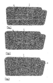
- the cross sections along the I-I line in Figures 4 and 9 show the lower semi-shell or body-base in both versions, without and with holes respectively.
- the following stage involves injecting the second plastic material (4), which can have conductive plating applied to it. Should holes (2) need to be formed during this second injection process these shall be covered by the corresponding second plastic material (4).
- This layer of second plastic mater (4) can be seen in Figures 10 and 11 and completely covers the surface of the holes (2) made beforehand. If no holes have been formed, this second layer of second plastic material (4) will be applied over the first layer of first plastic material, covering the surface corresponding to the outline of the corresponding electrical circuit, as detailed in Figures 5 and 6.
- Figure 3 shows the third stage, in which a conductor material (5) has already been applied to the body-base (3).
- the first plastic material used to form the lower semi-shell or body-base is not receptive to the conductor material, only the sections that are coated with the second plastic material (4) that is receptive to the conductor material will be coated with layers of said material (5) -either copper, nickel or silver- to form the electrical circuit for each specific application, for both the one detailed here and any other application (see Figures 7, 8, 12 and 13).
- This internal electrical circuit (5) will enable the different functional elements of the sun visor to be integrated, such as the connector, lamp holder, etc., and will also replace the conventional conductor.
- Figure 14 provides us with a possible means of assembling the unit according to the diagram of the invention. This process begins with the semi-shell being formed by following the three aforementioned stages.
- the upper semi-shell (6) is then placed on top of the lower semi-shell, which may include other features such as the hole (7) to receive a mirror, a light source, a cover (8) with the mirror (9) or the refractors.
- sun visor shaft such as bi-injection, metallic inserts, standard wiring or MID (moulded interconnect device) technology.
- a lining is later applied using standard techniques to complete the assembly of the unit in Figure 14.
Landscapes
- Engineering & Computer Science (AREA)
- Mechanical Engineering (AREA)
- Arrangements Of Lighting Devices For Vehicle Interiors, Mounting And Supporting Thereof, Circuits Therefore (AREA)
- Vehicle Step Arrangements And Article Storage (AREA)
- Transition And Organic Metals Composition Catalysts For Addition Polymerization (AREA)
- Acyclic And Carbocyclic Compounds In Medicinal Compositions (AREA)
- Vehicle Interior And Exterior Ornaments, Soundproofing, And Insulation (AREA)
- Shielding Devices Or Components To Electric Or Magnetic Fields (AREA)
Claims (4)
- Sonnenblende für Kraftfahrzeuge, gebildet aus einem Körper, der von einer Verkleidung abgedeckt ist und Folgendes umfasst:- einen inneren elektrischen Stromkreis,- einen Sonnenblendenschaft, von dem aus der innere Stromkreis mithilfe von Leitern, die an eine Fahrzeugbatterie und an den inneren elektrischen Stromkreis der Sonnenblende angeschlossen werden können, zugänglich ist.Dadurch gekennzeichnet, dass der Köper der Sonnenblende Folgendes umfasst:- Eine untere Halbschale (3) oder Körperbasis, die durch Einspritzen eines ersten Plastikmaterials gebildet wurde, auf das keine leitende Beschichtung aufgetragen werden kann, und die als Körper dient, der den inneren elektrischen Kreislauf, der in die Sonnenblende eingebaut ist, stützt,- Ein zweites Plastikmaterial (4), das auf den Umriss des inneren elektrischen Kreislaufs, der in den Körper der Sonnenblende eingeschlossen werden soll, aufgespritzt ist, auf das eine Beschichtung mit einem Leitermaterial (5) aufgetragen werden kann.- Ein Leitermaterial (5), das auf das zweite Plastikmaterial (4) aufgetragen ist, um den inneren elektrischen Stromkreis zu erzeugen- Eine obere Halbschale (6) aus einem eingespritzten Plastikmaterial, die ein Loch (7) umfasst, um den Spiegel (9), der auf der unteren Halbschale (3) oder Körperbasis angebracht ist, um den Körper zu bilden, unterzubringen.
- Sonnenblende nach Anspruch 1, dadurch gekennzeichnet, dass die untere Halbschale (3) ein Gehäuse einschließt, in das eine elektrische Vorrichtung eingeführt werden kann.
- Sonnenblende nach Anspruch 1, dadurch gekennzeichnet, dass die untere Halbschale (3), die die Köperbasis bildet, eine Vertiefung (2) aufweist, die mit der Oberfläche, die vom zweiten Plastikmaterial (4) abgedeckt werden soll, zusammenfällt.
- Verfahren zur Herstellung von Sonnenblenden, insbesondere für Kraftfahrzeuge, mit einem integrierten inneren elektrischen Stromkreis nach Anspruch 1, das Folgendes umfasst:- Bilden einer unteren Halbschale oder Körperbasis (3) durch Einspritzen eines ersten Plastikmaterials, auf das keine leitende Beschichtung aufgetragen werden kann,- Durchführen einer zweiten Einspritzung auf die untere Halbschale (3) mit einem zweiten Plastikmaterial (4), auf das eine leitende Beschichtung aufgetragen werden kann, um den Umriss des inneren elektrischen Stromkreises (2) zu bilden, der in den Körper der Sonnenblende integriert werden soll- Auftragen eines leitenden Materials (5) - Kupfer, Nickel oder Silber - auf die untere Halbschale oder Körperbasis (3) über das zweite Plastikmaterial (4), um den inneren elektrischen Stromkreis der Sonnenblende zu bilden,- Abdecken der unteren Halbschale oder Körperbasis (3) mit einer oberen Halbschale (6), um den vollständigen Körper der Sonnenblende zu bilden.- Optional Einführen eines Spiegels, einer Lichtquelle, einer Abdeckung (8) mit einem Spiegel (9) oder Refraktoren.- Fertigbearbeiten der Einheit mit einer Verkleidung unter Verwendung von Standardtechniken.
Applications Claiming Priority (1)
| Application Number | Priority Date | Filing Date | Title |
|---|---|---|---|
| PCT/ES2002/000278 WO2003104004A1 (es) | 2002-06-07 | 2002-06-07 | Parasol |
Publications (2)
| Publication Number | Publication Date |
|---|---|
| EP1514711A1 EP1514711A1 (de) | 2005-03-16 |
| EP1514711B1 true EP1514711B1 (de) | 2007-11-14 |
Family
ID=29724650
Family Applications (1)
| Application Number | Title | Priority Date | Filing Date |
|---|---|---|---|
| EP02735446A Expired - Lifetime EP1514711B1 (de) | 2002-06-07 | 2002-06-07 | Sonnenblende |
Country Status (11)
| Country | Link |
|---|---|
| EP (1) | EP1514711B1 (de) |
| JP (1) | JP2005529023A (de) |
| CN (1) | CN1538917A (de) |
| AT (1) | ATE378209T1 (de) |
| AU (1) | AU2002311185A1 (de) |
| BR (1) | BR0211709A (de) |
| CA (1) | CA2454777A1 (de) |
| DE (1) | DE60223600T2 (de) |
| ES (1) | ES2296936T3 (de) |
| MX (1) | MXPA04000925A (de) |
| WO (1) | WO2003104004A1 (de) |
Family Cites Families (5)
| Publication number | Priority date | Publication date | Assignee | Title |
|---|---|---|---|---|
| US4908740A (en) * | 1989-02-09 | 1990-03-13 | Hudgins Richard D | Integral composite structure with predetermined electrically conductive networks and method for producing same |
| JPH09156364A (ja) * | 1995-12-01 | 1997-06-17 | Kasai Kogyo Co Ltd | 自動車用サンバイザ |
| US6236373B1 (en) * | 1999-09-15 | 2001-05-22 | Humentech 21 Company | Vehicle sun visor with radio antenna |
| FR2814710B1 (fr) * | 2000-09-29 | 2003-02-14 | Grupo Antolin Vosges Sas | Dispositif d'alimentation electrique pour pare soleil de vehicule |
| US6382697B1 (en) * | 2000-11-29 | 2002-05-07 | Innotec Corporation | Stamping reinforced polymeric molded elbow and method of manufacture |
-
2002
- 2002-06-07 EP EP02735446A patent/EP1514711B1/de not_active Expired - Lifetime
- 2002-06-07 MX MXPA04000925A patent/MXPA04000925A/es active IP Right Grant
- 2002-06-07 DE DE60223600T patent/DE60223600T2/de not_active Expired - Fee Related
- 2002-06-07 JP JP2004511099A patent/JP2005529023A/ja active Pending
- 2002-06-07 AU AU2002311185A patent/AU2002311185A1/en not_active Abandoned
- 2002-06-07 ES ES02735446T patent/ES2296936T3/es not_active Expired - Lifetime
- 2002-06-07 AT AT02735446T patent/ATE378209T1/de not_active IP Right Cessation
- 2002-06-07 BR BR0211709-6A patent/BR0211709A/pt not_active IP Right Cessation
- 2002-06-07 CN CNA028152239A patent/CN1538917A/zh active Pending
- 2002-06-07 WO PCT/ES2002/000278 patent/WO2003104004A1/es not_active Ceased
- 2002-06-07 CA CA002454777A patent/CA2454777A1/en not_active Abandoned
Also Published As
| Publication number | Publication date |
|---|---|
| CN1538917A (zh) | 2004-10-20 |
| EP1514711A1 (de) | 2005-03-16 |
| BR0211709A (pt) | 2004-09-21 |
| WO2003104004A1 (es) | 2003-12-18 |
| MXPA04000925A (es) | 2004-04-02 |
| CA2454777A1 (en) | 2003-12-18 |
| JP2005529023A (ja) | 2005-09-29 |
| DE60223600D1 (de) | 2007-12-27 |
| ATE378209T1 (de) | 2007-11-15 |
| ES2296936T3 (es) | 2008-05-01 |
| AU2002311185A1 (en) | 2003-12-22 |
| DE60223600T2 (de) | 2008-09-18 |
Similar Documents
| Publication | Publication Date | Title |
|---|---|---|
| US5258892A (en) | Molded-in antenna with solderless interconnect | |
| CN100556240C (zh) | 集成机电设备和生产方法 | |
| CN102299403A (zh) | 电子装置壳体及其制作方法 | |
| EP1502788B1 (de) | Sonnenblende mit leitarm für fahrzeuge | |
| EP0473263B1 (de) | Fahrzeugsubstrat zur Befestigung von Komponenten | |
| EP1263147A2 (de) | Verbesswerungen in Mobilfunktelefone | |
| US20040074045A1 (en) | Electrical connectivity through a hinge | |
| WO2005046020A3 (de) | Elektromotor, sowie verfahren zur herstellung eines solchen | |
| CN1272158C (zh) | 移动通信终端机机壳制造方法、机壳和移动通信终端机 | |
| US20040149488A1 (en) | Flat flex cable | |
| US7053322B2 (en) | Gas bag module | |
| EP1307080B1 (de) | Elektronisches Modul und dessen Herstellungsverfahren | |
| EP4011593A1 (de) | Struktur mit in-mold-elektronik unter verwendung von plattierungsprozess und verfahren dafür | |
| CN117799403A (zh) | 移盖汽车遮阳板及其制备方法 | |
| EP1514711A1 (de) | Sonnenblende | |
| US6988901B2 (en) | Connector for printed circuit surface mounting and method for making same | |
| JPH07156725A (ja) | ドア用ワイヤーハーネス及びその製造方法 | |
| KR20050020736A (ko) | 썬바이저 | |
| JP4288740B2 (ja) | 導電部を有する樹脂成形品およびその製造方法 | |
| KR100781005B1 (ko) | 구성품 상에 부분조립품을 자동으로 조립하는 방법 | |
| KR101991275B1 (ko) | 안테나 구조 및 이의 제조 방법 | |
| JP4080607B2 (ja) | Led取付装置 | |
| CN104763253A (zh) | 一种门把手组件、汽车门把手及其安装方法 | |
| CN110896009A (zh) | 带电阻器的电刷式开关及其制造方法 | |
| CN101162810B (zh) | 连接装置及使用该连接装置的电连接器及其制造方法 |
Legal Events
| Date | Code | Title | Description |
|---|---|---|---|
| PUAI | Public reference made under article 153(3) epc to a published international application that has entered the european phase |
Free format text: ORIGINAL CODE: 0009012 |
|
| 17P | Request for examination filed |
Effective date: 20050104 |
|
| AK | Designated contracting states |
Kind code of ref document: A1 Designated state(s): AT BE CH CY DE DK ES FI FR GB GR IE IT LI LU MC NL PT SE TR |
|
| AX | Request for extension of the european patent |
Extension state: AL LT LV MK RO SI |
|
| DAX | Request for extension of the european patent (deleted) | ||
| GRAP | Despatch of communication of intention to grant a patent |
Free format text: ORIGINAL CODE: EPIDOSNIGR1 |
|
| RIN1 | Information on inventor provided before grant (corrected) |
Inventor name: UNANUE MURGUIONDO, INIGO Inventor name: OLIVAN AHEDO, CAROLINA |
|
| GRAS | Grant fee paid |
Free format text: ORIGINAL CODE: EPIDOSNIGR3 |
|
| GRAA | (expected) grant |
Free format text: ORIGINAL CODE: 0009210 |
|
| AK | Designated contracting states |
Kind code of ref document: B1 Designated state(s): AT BE CH CY DE DK ES FI FR GB GR IE IT LI LU MC NL PT SE TR |
|
| REG | Reference to a national code |
Ref country code: GB Ref legal event code: FG4D |
|
| REG | Reference to a national code |
Ref country code: CH Ref legal event code: EP |
|
| REG | Reference to a national code |
Ref country code: IE Ref legal event code: FG4D |
|
| REF | Corresponds to: |
Ref document number: 60223600 Country of ref document: DE Date of ref document: 20071227 Kind code of ref document: P |
|
| PG25 | Lapsed in a contracting state [announced via postgrant information from national office to epo] |
Ref country code: NL Free format text: LAPSE BECAUSE OF FAILURE TO SUBMIT A TRANSLATION OF THE DESCRIPTION OR TO PAY THE FEE WITHIN THE PRESCRIBED TIME-LIMIT Effective date: 20071114 Ref country code: LI Free format text: LAPSE BECAUSE OF FAILURE TO SUBMIT A TRANSLATION OF THE DESCRIPTION OR TO PAY THE FEE WITHIN THE PRESCRIBED TIME-LIMIT Effective date: 20071114 Ref country code: SE Free format text: LAPSE BECAUSE OF FAILURE TO SUBMIT A TRANSLATION OF THE DESCRIPTION OR TO PAY THE FEE WITHIN THE PRESCRIBED TIME-LIMIT Effective date: 20080214 Ref country code: CH Free format text: LAPSE BECAUSE OF FAILURE TO SUBMIT A TRANSLATION OF THE DESCRIPTION OR TO PAY THE FEE WITHIN THE PRESCRIBED TIME-LIMIT Effective date: 20071114 |
|
| NLV1 | Nl: lapsed or annulled due to failure to fulfill the requirements of art. 29p and 29m of the patents act | ||
| REG | Reference to a national code |
Ref country code: ES Ref legal event code: FG2A Ref document number: 2296936 Country of ref document: ES Kind code of ref document: T3 |
|
| PG25 | Lapsed in a contracting state [announced via postgrant information from national office to epo] |
Ref country code: FI Free format text: LAPSE BECAUSE OF FAILURE TO SUBMIT A TRANSLATION OF THE DESCRIPTION OR TO PAY THE FEE WITHIN THE PRESCRIBED TIME-LIMIT Effective date: 20071114 |
|
| REG | Reference to a national code |
Ref country code: CH Ref legal event code: PL |
|
| PG25 | Lapsed in a contracting state [announced via postgrant information from national office to epo] |
Ref country code: AT Free format text: LAPSE BECAUSE OF FAILURE TO SUBMIT A TRANSLATION OF THE DESCRIPTION OR TO PAY THE FEE WITHIN THE PRESCRIBED TIME-LIMIT Effective date: 20071114 |
|
| PG25 | Lapsed in a contracting state [announced via postgrant information from national office to epo] |
Ref country code: DK Free format text: LAPSE BECAUSE OF FAILURE TO SUBMIT A TRANSLATION OF THE DESCRIPTION OR TO PAY THE FEE WITHIN THE PRESCRIBED TIME-LIMIT Effective date: 20071114 |
|
| ET | Fr: translation filed | ||
| PG25 | Lapsed in a contracting state [announced via postgrant information from national office to epo] |
Ref country code: BE Free format text: LAPSE BECAUSE OF FAILURE TO SUBMIT A TRANSLATION OF THE DESCRIPTION OR TO PAY THE FEE WITHIN THE PRESCRIBED TIME-LIMIT Effective date: 20071114 |
|
| PLBE | No opposition filed within time limit |
Free format text: ORIGINAL CODE: 0009261 |
|
| STAA | Information on the status of an ep patent application or granted ep patent |
Free format text: STATUS: NO OPPOSITION FILED WITHIN TIME LIMIT |
|
| PG25 | Lapsed in a contracting state [announced via postgrant information from national office to epo] |
Ref country code: PT Free format text: LAPSE BECAUSE OF FAILURE TO SUBMIT A TRANSLATION OF THE DESCRIPTION OR TO PAY THE FEE WITHIN THE PRESCRIBED TIME-LIMIT Effective date: 20080414 |
|
| 26N | No opposition filed |
Effective date: 20080815 |
|
| PGFP | Annual fee paid to national office [announced via postgrant information from national office to epo] |
Ref country code: DE Payment date: 20080829 Year of fee payment: 7 |
|
| PG25 | Lapsed in a contracting state [announced via postgrant information from national office to epo] |
Ref country code: GR Free format text: LAPSE BECAUSE OF FAILURE TO SUBMIT A TRANSLATION OF THE DESCRIPTION OR TO PAY THE FEE WITHIN THE PRESCRIBED TIME-LIMIT Effective date: 20080215 Ref country code: MC Free format text: LAPSE BECAUSE OF NON-PAYMENT OF DUE FEES Effective date: 20080630 |
|
| GBPC | Gb: european patent ceased through non-payment of renewal fee |
Effective date: 20080607 |
|
| PG25 | Lapsed in a contracting state [announced via postgrant information from national office to epo] |
Ref country code: IE Free format text: LAPSE BECAUSE OF NON-PAYMENT OF DUE FEES Effective date: 20080609 |
|
| PG25 | Lapsed in a contracting state [announced via postgrant information from national office to epo] |
Ref country code: GB Free format text: LAPSE BECAUSE OF NON-PAYMENT OF DUE FEES Effective date: 20080607 |
|
| PG25 | Lapsed in a contracting state [announced via postgrant information from national office to epo] |
Ref country code: CY Free format text: LAPSE BECAUSE OF FAILURE TO SUBMIT A TRANSLATION OF THE DESCRIPTION OR TO PAY THE FEE WITHIN THE PRESCRIBED TIME-LIMIT Effective date: 20071114 |
|
| PG25 | Lapsed in a contracting state [announced via postgrant information from national office to epo] |
Ref country code: DE Free format text: LAPSE BECAUSE OF NON-PAYMENT OF DUE FEES Effective date: 20100101 |
|
| PG25 | Lapsed in a contracting state [announced via postgrant information from national office to epo] |
Ref country code: LU Free format text: LAPSE BECAUSE OF NON-PAYMENT OF DUE FEES Effective date: 20080607 |
|
| PG25 | Lapsed in a contracting state [announced via postgrant information from national office to epo] |
Ref country code: TR Free format text: LAPSE BECAUSE OF FAILURE TO SUBMIT A TRANSLATION OF THE DESCRIPTION OR TO PAY THE FEE WITHIN THE PRESCRIBED TIME-LIMIT Effective date: 20071114 |
|
| PG25 | Lapsed in a contracting state [announced via postgrant information from national office to epo] |
Ref country code: IT Free format text: LAPSE BECAUSE OF NON-PAYMENT OF DUE FEES Effective date: 20080630 |
|
| PGFP | Annual fee paid to national office [announced via postgrant information from national office to epo] |
Ref country code: FR Payment date: 20130717 Year of fee payment: 12 |
|
| REG | Reference to a national code |
Ref country code: FR Ref legal event code: ST Effective date: 20150227 |
|
| PG25 | Lapsed in a contracting state [announced via postgrant information from national office to epo] |
Ref country code: FR Free format text: LAPSE BECAUSE OF NON-PAYMENT OF DUE FEES Effective date: 20140630 |
|
| PGFP | Annual fee paid to national office [announced via postgrant information from national office to epo] |
Ref country code: ES Payment date: 20150422 Year of fee payment: 14 |
|
| PG25 | Lapsed in a contracting state [announced via postgrant information from national office to epo] |
Ref country code: ES Free format text: LAPSE BECAUSE OF NON-PAYMENT OF DUE FEES Effective date: 20160608 |
|
| REG | Reference to a national code |
Ref country code: ES Ref legal event code: FD2A Effective date: 20181203 |