EP1512968B1 - Elektrochemische Gassensoranordnung - Google Patents
Elektrochemische Gassensoranordnung Download PDFInfo
- Publication number
- EP1512968B1 EP1512968B1 EP04029324A EP04029324A EP1512968B1 EP 1512968 B1 EP1512968 B1 EP 1512968B1 EP 04029324 A EP04029324 A EP 04029324A EP 04029324 A EP04029324 A EP 04029324A EP 1512968 B1 EP1512968 B1 EP 1512968B1
- Authority
- EP
- European Patent Office
- Prior art keywords
- reservoir
- sensor assembly
- capillary
- assembly according
- gas sensor
- Prior art date
- Legal status (The legal status is an assumption and is not a legal conclusion. Google has not performed a legal analysis and makes no representation as to the accuracy of the status listed.)
- Expired - Lifetime
Links
- 239000003792 electrolyte Substances 0.000 claims description 26
- 230000004888 barrier function Effects 0.000 claims description 5
- 238000009792 diffusion process Methods 0.000 claims description 5
- 239000000463 material Substances 0.000 claims description 5
- 239000004033 plastic Substances 0.000 claims description 2
- 229920003023 plastic Polymers 0.000 claims description 2
- 238000004519 manufacturing process Methods 0.000 description 4
- 239000004810 polytetrafluoroethylene Substances 0.000 description 4
- 229920001343 polytetrafluoroethylene Polymers 0.000 description 4
- 230000000712 assembly Effects 0.000 description 2
- 238000000429 assembly Methods 0.000 description 2
- 238000010276 construction Methods 0.000 description 2
- XLYOFNOQVPJJNP-UHFFFAOYSA-N water Substances O XLYOFNOQVPJJNP-UHFFFAOYSA-N 0.000 description 2
- 238000009736 wetting Methods 0.000 description 2
- OKTJSMMVPCPJKN-UHFFFAOYSA-N Carbon Chemical compound [C] OKTJSMMVPCPJKN-UHFFFAOYSA-N 0.000 description 1
- 238000011109 contamination Methods 0.000 description 1
- 238000001035 drying Methods 0.000 description 1
- 229910021397 glassy carbon Inorganic materials 0.000 description 1
- 239000007788 liquid Substances 0.000 description 1
- 239000012528 membrane Substances 0.000 description 1
- 238000000034 method Methods 0.000 description 1
- 239000002991 molded plastic Substances 0.000 description 1
- 239000004417 polycarbonate Substances 0.000 description 1
- 229920000515 polycarbonate Polymers 0.000 description 1
- 230000026041 response to humidity Effects 0.000 description 1
- 230000002441 reversible effect Effects 0.000 description 1
- 238000007789 sealing Methods 0.000 description 1
- 239000007787 solid Substances 0.000 description 1
- 229920001169 thermoplastic Polymers 0.000 description 1
- 239000004416 thermosoftening plastic Substances 0.000 description 1
Images
Classifications
-
- G—PHYSICS
- G01—MEASURING; TESTING
- G01N—INVESTIGATING OR ANALYSING MATERIALS BY DETERMINING THEIR CHEMICAL OR PHYSICAL PROPERTIES
- G01N27/00—Investigating or analysing materials by the use of electric, electrochemical, or magnetic means
- G01N27/26—Investigating or analysing materials by the use of electric, electrochemical, or magnetic means by investigating electrochemical variables; by using electrolysis or electrophoresis
- G01N27/403—Cells and electrode assemblies
- G01N27/404—Cells with anode, cathode and cell electrolyte on the same side of a permeable membrane which separates them from the sample fluid, e.g. Clark-type oxygen sensors
Definitions
- the invention relates to an electrochemical gas sensor assembly of the kind comprising an electrochemical gas sensor having sensing and counter electrodes, a gas phase diffusion barrier for controlling the passage of gas to the sensing electrode, an electrolyte reservoir, and means for conveying electrolyte between the reservoir and the sensing and counter electrodes.
- electrochemical gas sensor assemblies are hereinafter referred to as of the kind described.
- an electrochemical gas sensor assembly of the kind described is shown in GB-A-2094005 .
- the reservoir is provided in a hollowed out bottom plate which has a covering flange which supports the various components of the sensor including the sensing and counter electrodes and, where provided, a reference electrode.
- Electrolyte passes through a small aperture in the covering flange in a wick extending into the reservoir and extending through apertures in some of the components and into contact with hydrophilic separators to convey electrolyte to the region between the electrodes.
- the use of a wick is undesirable due to the complex manufacturing techniques required to thread the wick through the various components.
- the arrangement requires an additional rear vent which provides a possible source of leakage as well as leading to a more complex construction.
- the conveying means as a porous, block-like body positioned in the reservoir and at least partly supporting other components of the sensor. This is described in more detail in EP-A-0604012 .
- this approach leads to a simpler assembly and the ability to pre-fill the reservoir, it has the disadvantages of relatively high cost and some difficulties in assembly because the block-like body tends to float in the electrolyte.
- the tolerances achievable with materials for the block such as Reticulated Vitreous Carbon (RVC) are not compatible with the manufacturing tolerances required and there is also a risk of contamination when the block-like body is cut.
- RVC Reticulated Vitreous Carbon
- US-A-4532023 describes an electrochemical gas analyser in which a pair of electrochemical cells defining measuring and reference cells respectively are provided and through which electrolyte is pumped so that the electrolyte is passed through an SO 2 filter.
- an electrochemical gas sensor of the kind described and as defined by claim 1 is characterized in that the means for conveying electrolyte between the reservoir and the sensing and counter electrodes includes at least one capillary defined by substantially rigid, non-porous walls, whereby in use the capillary draws electrolyte therethrough to between the sensing and counter electrodes.
- the capillary walls may be defined by an integral part of the reservoir, for example the reservoir could be made from moulded plastics and include the at least one capillary.
- the capillary walls are defined by cooperating parts of the reservoir and a substantially rigid, non-porous body. Conveniently, the body is removable from the reservoir although this is not essential.
- the walls of the capillary could be defined but conveniently, where a substantially rigid, non-porous body is provided, the reservoir includes an upstanding wall, the body having an aperture into which the upstanding wall is positioned so that the at least one capillary is defined between the upstanding wall and the body. Not only does this provide a very convenient way of defining the or each capillary but in addition the upstanding wall assists in locating the body within the reservoir which is useful both during assembly and in use.
- the at least one capillary could be defined between the body and an outer wall of the reservoir.
- the capillary could have an annular form extending around the upstanding wall and carrying electrolyte along the upstanding wall but preferably the reservoir includes a number of upstanding walls each extending into the aperture of the body to define respective capillaries.
- the reservoir includes a number of upstanding walls each extending into the aperture of the body to define respective capillaries.
- one or both of the or each upstanding wall and the body aperture have ribs which extend between the body and the respective upstanding walls so as to define the lateral extent of the or each capillary. In this way, it will be possible to define more than one capillary extending along the length of the or each upstanding wall.
- the or each capillary could simply extend along the length of the or each upstanding wall. This would be acceptable if the sensor was used in a single orientation in which electrolyte was encouraged to flow to the base of the upstanding wall where it could be received in the capillary. In practice, however, the orientation of the sensor will vary during use and preferably, therefore, part of the at least one capillary is defined between the body and a base of the reservoir. In this way, electrolyte can be obtained from parts of the base spaced from the upstanding wall and then conveyed by that part of the capillary defined between the body and the base to the upstanding wall(s) for onward transport to the gas sensor.
- the part of the body which cooperates with the base could take a variety of forms, for example the body could include one or more laterally extending arms but conveniently the body has a first flange extending across the base but spaced therefrom to define the part of the at least one capillary.
- the body and the first flange have a number of ribs which extend between the base and the flange to define the part of the at least one capillary.
- the body has a second flange positioned adjacent the gas sensor so as partly to support the gas sensor.
- the sensor assembly could be reoriented and thus preferably one or both of the second flange and facing surface of the gas sensor have a number of ribs which extend therebetween to define one or more capillaries for conveying electrolyte.
- the first and/or second flanges has one or more apertures extending therethrough. Providing apertures in the second flange also assists in filling the reservoir during assembly and wetting the adjacent gas sensor surface.
- a rear air vent is not essential and conveniently the second flange is spaced from the reservoir wall to define an air vent.
- the gas sensor may include a reference electrode.
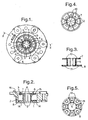
- the reservoir shown in Figures 1 and 2 which is to be fitted to a gas sensor, includes a base 1 ( Figure 2 ) integrally moulded with an upstanding, annular outer wall 2 defining an electrolyte cavity 3.
- a set of four integrally moulded, circumferentially spaced, upstanding walls 4 extend from the centre of the base 1.
- annular sleeve 6 having upper and lower flanges 7,8 integrally formed therewith fits onto the walls 4 as can be seen most clearly in Figure 2 .
- the sleeve 6 is a close fit on the walls 4 so as to define four elongate capillaries 9.
- the sleeve 6 has four pairs of ribs 5 which extend parallel with the walls 4 to define the lateral extent of each capillary 9.
- the radial width of each capillary 9 is about 0.2mm.
- Each of the upper and lower flanges 7,8 is formed with a number of circumferentially spaced apertures 10,11 respectively ( Figures 3-5 ) and is also formed with a set of substantially equally circumferentially spaced and axially outward facing ribs 12,13 respectively which are aligned with the ribs 5.
- the ribs 13 on the flange 8 cooperate with the base 1 of the reservoir to define a number of radially extending capillaries 14 between each pair of ribs, these capillaries having a height (as seen in Figure 2 ) of between 0.2 and 0.3mm.
- a similar set of capillaries is formed between the ribs 12 and the lowermost part of the gas sensor (as shown in Figures 1-5 ).
- the apertures 10,11 are provided for a number of reasons. Firstly, they reduce the volume taken up by the flanges 7,8. The apertures 10, however, also facilitate filling of the reservoir which can be achieved through the apertures 10 and also assist in wetting the adjacent surface of the gas sensor.
- the upper flange 7 has a radius less than that of the inner surface of the wall 2 so as to define an annular gap 15. This provides an air vent as will be described below.
- the material of the walls 4 and the sleeve 6 is non-porous and substantially rigid and conveniently is formed of a plastics material such as ABS or polycarbonate. In general, any thermoplastic will be suitable which is compatible with the electrolyte to be used.
- the base and wall 1,2 of the reservoir and the walls 4 are formed as an integral, moulded part which is assembled with a moulded body defining the sleeve 6 and flanges 7,8. Electrolyte is then supplied to the reservoir (typically about 1cc) and then the gas sensor is assembled on top of the reservoir and secured to it.
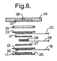
- the components of the gas sensor can take a variety of forms, one example of which is shown in Figure 6 .
- a PTFE tape floor seal 26 Positioned immediately above the flange 7 and partially supported by the flange and partly by a ledge 16 of the wall 2 are positioned a PTFE tape floor seal 26, a hydrophilic separator 17, a current collector 18 and a counter electrode 22.
- a separator 27 of hydrophilic material is positioned above the counter electrode 22 followed by a current collector 28, a reference electrode 29, a separator 31, a current collector 32 and a sensing electrode 33.
- Each of the electrodes is provided on PTFE backing tape.
- the components are held in place by sealing a top plate 34 onto the reservoir, the various components being urged into contact by an "O"-ring 35.
- the top plate 34 has a capillary hole 36 which forms a gas phase diffusion barrier for restricting access of the gas to be detected, the top plate also having a cavity 37 to allow for lateral diffusion of the gas across the sensing electrode 33.
- a Knudsen barrier or solid membrane could be used.
- the electrolyte will not automatically wet the sensor components.
- the sensor is therefore inverted to cause the electrolyte in the reservoir to prime or wet the sensor components through the holes 10 which will then draw electrolyte through the capillaries 9.
- the electrolyte loses water, further electrolyte is drawn up through the capillaries 14 and then 9 and is fed through an aperture 30 in the counter electrode 22 and into the region between the electrodes.
- air can enter the reservoir through the PTFE backing tapes and through the air vent 15.
- the reverse action will take place with liquid being drawn back through the capillaries into the reservoir. In this case, air is displaced out of the reservoir through the air vent 15 and across the PTFE backing tapes and out to the atmosphere.
- the upper flange 7 provides strong, rigid support for the gas sensor components. It should be noted, however, that the upper flange 7 (and lower flange 8) need not have an annular form but could be formed by one or more radially extending arms.
Landscapes
- Chemical & Material Sciences (AREA)
- Life Sciences & Earth Sciences (AREA)
- Health & Medical Sciences (AREA)
- Physics & Mathematics (AREA)
- Chemical Kinetics & Catalysis (AREA)
- Electrochemistry (AREA)
- Molecular Biology (AREA)
- Analytical Chemistry (AREA)
- Biochemistry (AREA)
- General Health & Medical Sciences (AREA)
- General Physics & Mathematics (AREA)
- Immunology (AREA)
- Pathology (AREA)
- Measuring Oxygen Concentration In Cells (AREA)
- Investigating Or Analyzing Materials By The Use Of Electric Means (AREA)
Claims (12)
- Anordnung eines elektrochemischen Gassensors, die einen elektrochemischen Gassensor mit einer Erfassungselektrode (33) und einer Gegenelektrode (22), eine Gasphasendiffusionssperre (36) zum Steuern des Durchgangs von Gas zu der Erfassungselektrode (33), einen Elektrolyt-Vorratsbehälter (3) und Mittel zum Befördern von Elektrolyt zwischen dem Vorratsbehälter (3) und den Erfassungs- und Gegenelektroden (33, 22) enthält, wobei die Mittel zum Befördern von Elektrolyt zwischen dem Vorratsbehälter (3) und den Erfassungs- und Gegenelektroden (33, 22) wenigstens ein Kapillarelement (9) enthalten, wobei die Anordnung eines elektrochemischen Gassensors dadurch gekennzeichnet ist, dass das wenigstens eine Kapillarelement durch im Wesentlichen starre, nicht poröse Wände definiert ist, wodurch das Kapillarelement (9) im Gebrauch Elektrolyt hindurch und zwischen die Erfassungs- und Gegenelektroden (33, 22) zieht,
wobei die Kapillarwände durch zusammenwirkende Teile (4) des Vorratsbehälters und einen im Wesentlichen starren, nicht porösen Körper (6) definiert sind,
wobei der Vorratsbehälter eine aufrechtstehende Wand (4) aufweist, der Körper (6) eine Öffnung besitzt, in die die aufrechtstehende Wand so eingesetzt ist, dass das wenigstens eine Kapillarelement (9) zwischen der aufrechtstehenden Wand und dem Körper definiert ist,
wobei der Körper einen ersten Flansch (7) besitzt, der in der Nähe des Gassensors positioniert ist, um den Gassensor teilweise zu unterstützen,
wobei der erste Flansch (7) und/oder die zugewandte Oberfläche des Gassensors eine Anzahl von Rippen (12) besitzen, die sich dazwischen erstrecken, um ein oder mehrere Kapillarelemente zum Befördern von Elektrolyt zu definieren. - Sensoranordnung nach Anspruch 1, wobei der Vorratsbehälter zahlreiche aufrechtstehende Wände (4) aufweist, die sich jeweils in die Öffnung des Körpers (6) erstrecken, um jeweilige Kapillarelemente (9) zu definieren.
- Sensoranordnung nach Anspruch 2, wobei die aufrechtstehenden Wände (4) in Umfangsrichtung beabstandet sind.
- Sensoranordnung nach Anspruch 2 oder Anspruch 3, wobei die oder jede aufrechtstehende Wand (4) und/oder die Körperöffnung Rippen (5) besitzen, die sich zwischen dem Körper und den jeweiligen aufrechtstehenden Wänden erstrecken, um die seitliche Erstreckung des oder jedes Kapillarelements zu definieren.
- Sensoranordnung nach einem der Ansprüche 2 bis 4, wobei der Körper aus dem Vorratsbehälter entnehmbar ist.
- Sensoranordnung nach einem der Ansprüche 2 bis 5, wobei ein Teil des wenigstens einen Kapillarelements (9) zwischen dem Körper und einer Basis des Vorratsbehälters definiert ist.
- Sensoranordnung nach Anspruch 6, wobei der Körper einen zweiten Flansch (8) besitzt, der sich über die Basis (1) erstreckt, jedoch hiervon beabstandet ist, um den Teil des wenigstens einen Kapillarelements zu definieren.
- Sensoranordnung nach Anspruch 7, wobei die Basis (1) und/oder der zweite Flansch (8) zahlreiche Rippen (13) besitzen, die sich zwischen der Basis und dem Flansch erstrecken, um den Teil des wenigstens einen Kapillarelements zu definieren.
- Sensoranordnung nach einem der Ansprüche 1, 7 oder 8, wobei der erste und/oder der zweite Flansch (8, 7) eine oder mehrere Öffnungen (11, 10) besitzen, die durch sie verlaufen.
- Sensoranordnung nach Anspruch 1 oder Anspruch 9, wobei der zweite Flansch (7) von der Vorratsbehälterwand beabstandet ist, um eine Entlüftung zu definieren.
- Sensoranordnung nach einem der Ansprüche 2 bis 10, wobei der Körper aus Kunststoff hergestellt ist.
- Sensoranordnung nach einem der vorhergehenden Ansprüche, wobei der Gassensor ferner eine Bezugselektrode enthält.
Applications Claiming Priority (3)
| Application Number | Priority Date | Filing Date | Title |
|---|---|---|---|
| GBGB9517620.2A GB9517620D0 (en) | 1995-08-29 | 1995-08-29 | Electrochemical gas sensor assembly |
| GB9517620 | 1995-08-29 | ||
| EP96304344A EP0763730B1 (de) | 1995-08-29 | 1996-06-10 | Elektrochemische Gassensoranordnung |
Related Parent Applications (2)
| Application Number | Title | Priority Date | Filing Date |
|---|---|---|---|
| EP96304344.3 Division | 1996-06-10 | ||
| EP96304344A Division EP0763730B1 (de) | 1995-08-29 | 1996-06-10 | Elektrochemische Gassensoranordnung |
Publications (2)
| Publication Number | Publication Date |
|---|---|
| EP1512968A1 EP1512968A1 (de) | 2005-03-09 |
| EP1512968B1 true EP1512968B1 (de) | 2011-05-04 |
Family
ID=10779887
Family Applications (2)
| Application Number | Title | Priority Date | Filing Date |
|---|---|---|---|
| EP96304344A Expired - Lifetime EP0763730B1 (de) | 1995-08-29 | 1996-06-10 | Elektrochemische Gassensoranordnung |
| EP04029324A Expired - Lifetime EP1512968B1 (de) | 1995-08-29 | 1996-06-10 | Elektrochemische Gassensoranordnung |
Family Applications Before (1)
| Application Number | Title | Priority Date | Filing Date |
|---|---|---|---|
| EP96304344A Expired - Lifetime EP0763730B1 (de) | 1995-08-29 | 1996-06-10 | Elektrochemische Gassensoranordnung |
Country Status (5)
| Country | Link |
|---|---|
| US (1) | US5632875A (de) |
| EP (2) | EP0763730B1 (de) |
| CA (1) | CA2179311C (de) |
| DE (2) | DE69634028T2 (de) |
| GB (1) | GB9517620D0 (de) |
Families Citing this family (10)
| Publication number | Priority date | Publication date | Assignee | Title |
|---|---|---|---|---|
| CA2255472C (en) * | 1998-12-10 | 2005-02-22 | Senco Sensors Inc. | Electrochemical gas sensor with gas communication means |
| CA2262355C (en) * | 1999-02-23 | 2004-06-01 | Senco Sensors Inc. | Protection of gas communication in an electrochemical sensor |
| US6428664B1 (en) | 2000-06-19 | 2002-08-06 | Roche Diagnostics Corporation | Biosensor |
| JP3865114B2 (ja) * | 2000-08-01 | 2007-01-10 | 理研計器株式会社 | 電気化学式ガスセンサー |
| GB0027877D0 (en) * | 2000-11-15 | 2000-12-27 | Alphasense Ltd | Electrochemical gas sensor |
| US6830730B2 (en) | 2001-09-11 | 2004-12-14 | Spectrolanalytical Instruments | Method and apparatus for the on-stream analysis of total sulfur and/or nitrogen in petroleum products |
| DE102006024022B4 (de) * | 2006-05-23 | 2008-05-08 | It Dr. Gambert Gmbh | Bleifreier galvanischer Sauerstoffsensor |
| WO2008057744A2 (en) * | 2006-11-01 | 2008-05-15 | Sensorcon, Inc. | Sensors and methods of making the same |
| CN108027338B (zh) * | 2015-07-22 | 2020-11-17 | 霍尼韦尔国际公司 | 一种电化学传感器及在其内输送电解质的方法 |
| EP3341717B1 (de) | 2015-08-24 | 2025-08-13 | Honeywell International Inc. | Sensorelektrodensauerstoffsteuerung in einem sauerstoffsensor |
Family Cites Families (8)
| Publication number | Priority date | Publication date | Assignee | Title |
|---|---|---|---|---|
| US3103480A (en) * | 1958-12-10 | 1963-09-10 | Double bridge electrode for electro- | |
| US3329599A (en) * | 1964-12-30 | 1967-07-04 | Mast Dev Company | Apparatus for measuring trace constituents |
| US3713994A (en) * | 1971-03-16 | 1973-01-30 | Atomic Energy Commission | Electrochemical air pollution monitoring device and method of use thereof |
| GB1385201A (en) * | 1971-05-06 | 1975-02-26 | Nat Res Dev | Eleczrochemical cells |
| US4310399A (en) * | 1979-07-23 | 1982-01-12 | Eastman Kodak Company | Liquid transport device containing means for delaying capillary flow |
| GB2094005B (en) | 1981-02-03 | 1985-05-30 | Coal Industry Patents Ltd | Electrochemical gas sensor |
| US4532023A (en) | 1983-03-12 | 1985-07-30 | Kernforschungsanlage Julich Gmbh | Electrochemical gas analyzer for determination of sulphur dioxide content of gases |
| GB9226937D0 (en) * | 1992-12-24 | 1993-02-17 | City Tech | Electrochemical gas sensor |
-
1995
- 1995-08-29 GB GBGB9517620.2A patent/GB9517620D0/en active Pending
-
1996
- 1996-06-10 DE DE69634028T patent/DE69634028T2/de not_active Expired - Lifetime
- 1996-06-10 EP EP96304344A patent/EP0763730B1/de not_active Expired - Lifetime
- 1996-06-10 DE DE69638370T patent/DE69638370D1/de not_active Expired - Lifetime
- 1996-06-10 EP EP04029324A patent/EP1512968B1/de not_active Expired - Lifetime
- 1996-06-17 CA CA002179311A patent/CA2179311C/en not_active Expired - Fee Related
- 1996-06-26 US US08/673,727 patent/US5632875A/en not_active Expired - Lifetime
Also Published As
| Publication number | Publication date |
|---|---|
| DE69634028T2 (de) | 2005-08-04 |
| EP1512968A1 (de) | 2005-03-09 |
| DE69634028D1 (de) | 2005-01-20 |
| EP0763730B1 (de) | 2004-12-15 |
| CA2179311A1 (en) | 1997-03-01 |
| GB9517620D0 (en) | 1995-11-01 |
| DE69638370D1 (de) | 2011-06-16 |
| US5632875A (en) | 1997-05-27 |
| EP0763730A1 (de) | 1997-03-19 |
| CA2179311C (en) | 2006-10-17 |
Similar Documents
| Publication | Publication Date | Title |
|---|---|---|
| EP1512968B1 (de) | Elektrochemische Gassensoranordnung | |
| US5395507A (en) | Electrochemical gas sensor | |
| US3909302A (en) | Vent cap for batteries | |
| US5830337A (en) | Electrochemical gas sensor | |
| JPH0455265B2 (de) | ||
| US5272020A (en) | Cylindrical alkaline manganese dioxide-zinc cell with improved bottom sealing | |
| JPH11503826A (ja) | 電極領域の規定方法 | |
| US8535498B2 (en) | Electrochemical gas sensor and method for clamping the same | |
| EP4212862B1 (de) | Elektrochemische gassensoranordnung | |
| WO2002027820A3 (en) | Impregnated separator for electrochemical cell and method of making same | |
| EP1179731A2 (de) | Galvanischer Gassensor mit einer Sauerstoff reduzierenden Gegenelektrode | |
| JP7141962B2 (ja) | 定電位電解式ガスセンサ | |
| US4198280A (en) | Membrane support structure for electrochemical sensing probe | |
| CN114965648A (zh) | 氧气传感器 | |
| JP6989448B2 (ja) | 定電位電解式酸素センサ | |
| JP7416269B2 (ja) | 細胞培養容器及び細胞培養システム | |
| US7601233B2 (en) | Electrochemical gas sensor with passage for receiving gas | |
| US20070187241A1 (en) | Electrochemical gas sensor with reduced wake-up time | |
| GB2160322A (en) | Electrochemical gas sensor | |
| JP3042616B2 (ja) | 定電位電解式ガスセンサ | |
| CN218766749U (zh) | 一种参比电极膜组 | |
| JP2001321366A (ja) | 血漿又は血清採取具 | |
| JPH0679021B2 (ja) | 拡散収集装置 | |
| EP0097553A3 (de) | Sauerstofffühler mit wasseraufsaugender Membran | |
| JP2004233319A (ja) | 電気化学式ガスセンサー |
Legal Events
| Date | Code | Title | Description |
|---|---|---|---|
| PUAI | Public reference made under article 153(3) epc to a published international application that has entered the european phase |
Free format text: ORIGINAL CODE: 0009012 |
|
| AC | Divisional application: reference to earlier application |
Ref document number: 0763730 Country of ref document: EP Kind code of ref document: P |
|
| AK | Designated contracting states |
Kind code of ref document: A1 Designated state(s): DE FR GB IT |
|
| RIN1 | Information on inventor provided before grant (corrected) |
Inventor name: CHAPPLES, JOHN Inventor name: SEWELL, PETER JOHN |
|
| 17P | Request for examination filed |
Effective date: 20050831 |
|
| AKX | Designation fees paid |
Designated state(s): DE FR GB IT |
|
| 17Q | First examination report despatched |
Effective date: 20080415 |
|
| GRAP | Despatch of communication of intention to grant a patent |
Free format text: ORIGINAL CODE: EPIDOSNIGR1 |
|
| GRAS | Grant fee paid |
Free format text: ORIGINAL CODE: EPIDOSNIGR3 |
|
| GRAA | (expected) grant |
Free format text: ORIGINAL CODE: 0009210 |
|
| AC | Divisional application: reference to earlier application |
Ref document number: 0763730 Country of ref document: EP Kind code of ref document: P |
|
| AK | Designated contracting states |
Kind code of ref document: B1 Designated state(s): DE FR GB IT |
|
| REG | Reference to a national code |
Ref country code: GB Ref legal event code: FG4D |
|
| REF | Corresponds to: |
Ref document number: 69638370 Country of ref document: DE Date of ref document: 20110616 Kind code of ref document: P |
|
| REG | Reference to a national code |
Ref country code: DE Ref legal event code: R096 Ref document number: 69638370 Country of ref document: DE Effective date: 20110616 |
|
| PLBE | No opposition filed within time limit |
Free format text: ORIGINAL CODE: 0009261 |
|
| STAA | Information on the status of an ep patent application or granted ep patent |
Free format text: STATUS: NO OPPOSITION FILED WITHIN TIME LIMIT |
|
| 26N | No opposition filed |
Effective date: 20120207 |
|
| REG | Reference to a national code |
Ref country code: DE Ref legal event code: R097 Ref document number: 69638370 Country of ref document: DE Effective date: 20120207 |
|
| PGFP | Annual fee paid to national office [announced via postgrant information from national office to epo] |
Ref country code: GB Payment date: 20120525 Year of fee payment: 17 Ref country code: FR Payment date: 20120614 Year of fee payment: 17 |
|
| PGFP | Annual fee paid to national office [announced via postgrant information from national office to epo] |
Ref country code: IT Payment date: 20120618 Year of fee payment: 17 |
|
| PGFP | Annual fee paid to national office [announced via postgrant information from national office to epo] |
Ref country code: DE Payment date: 20120629 Year of fee payment: 17 |
|
| GBPC | Gb: european patent ceased through non-payment of renewal fee |
Effective date: 20130610 |
|
| REG | Reference to a national code |
Ref country code: DE Ref legal event code: R119 Ref document number: 69638370 Country of ref document: DE Effective date: 20140101 |
|
| REG | Reference to a national code |
Ref country code: FR Ref legal event code: ST Effective date: 20140228 |
|
| PG25 | Lapsed in a contracting state [announced via postgrant information from national office to epo] |
Ref country code: DE Free format text: LAPSE BECAUSE OF NON-PAYMENT OF DUE FEES Effective date: 20140101 Ref country code: GB Free format text: LAPSE BECAUSE OF NON-PAYMENT OF DUE FEES Effective date: 20130610 |
|
| PG25 | Lapsed in a contracting state [announced via postgrant information from national office to epo] |
Ref country code: FR Free format text: LAPSE BECAUSE OF NON-PAYMENT OF DUE FEES Effective date: 20130701 Ref country code: IT Free format text: LAPSE BECAUSE OF NON-PAYMENT OF DUE FEES Effective date: 20130610 |