EP1512853B1 - Zufuhrkreis für den Luftansaugkrümmer einer Fahrzeugbrennkraftmaschine - Google Patents
Zufuhrkreis für den Luftansaugkrümmer einer Fahrzeugbrennkraftmaschine Download PDFInfo
- Publication number
- EP1512853B1 EP1512853B1 EP04300486A EP04300486A EP1512853B1 EP 1512853 B1 EP1512853 B1 EP 1512853B1 EP 04300486 A EP04300486 A EP 04300486A EP 04300486 A EP04300486 A EP 04300486A EP 1512853 B1 EP1512853 B1 EP 1512853B1
- Authority
- EP
- European Patent Office
- Prior art keywords
- air
- branch
- butterflies
- intake manifold
- pipe
- Prior art date
- Legal status (The legal status is an assumption and is not a legal conclusion. Google has not performed a legal analysis and makes no representation as to the accuracy of the status listed.)
- Expired - Lifetime
Links
- 238000002485 combustion reaction Methods 0.000 title claims 2
- 241000255777 Lepidoptera Species 0.000 claims description 24
- 230000000750 progressive effect Effects 0.000 claims description 9
- 239000012528 membrane Substances 0.000 claims description 7
- 230000001360 synchronised effect Effects 0.000 claims description 7
- 235000001954 papillon Nutrition 0.000 description 8
- 244000229285 papillon Species 0.000 description 4
- 238000001816 cooling Methods 0.000 description 2
- 238000000034 method Methods 0.000 description 2
- 230000008878 coupling Effects 0.000 description 1
- 238000010168 coupling process Methods 0.000 description 1
- 238000005859 coupling reaction Methods 0.000 description 1
- 238000002513 implantation Methods 0.000 description 1
- 230000009191 jumping Effects 0.000 description 1
- 230000001105 regulatory effect Effects 0.000 description 1
- 238000007789 sealing Methods 0.000 description 1
- 238000011144 upstream manufacturing Methods 0.000 description 1
Images


Classifications
-
- F—MECHANICAL ENGINEERING; LIGHTING; HEATING; WEAPONS; BLASTING
- F02—COMBUSTION ENGINES; HOT-GAS OR COMBUSTION-PRODUCT ENGINE PLANTS
- F02B—INTERNAL-COMBUSTION PISTON ENGINES; COMBUSTION ENGINES IN GENERAL
- F02B29/00—Engines characterised by provision for charging or scavenging not provided for in groups F02B25/00, F02B27/00 or F02B33/00 - F02B39/00; Details thereof
- F02B29/04—Cooling of air intake supply
- F02B29/0406—Layout of the intake air cooling or coolant circuit
- F02B29/0418—Layout of the intake air cooling or coolant circuit the intake air cooler having a bypass or multiple flow paths within the heat exchanger to vary the effective heat transfer surface
-
- F—MECHANICAL ENGINEERING; LIGHTING; HEATING; WEAPONS; BLASTING
- F02—COMBUSTION ENGINES; HOT-GAS OR COMBUSTION-PRODUCT ENGINE PLANTS
- F02B—INTERNAL-COMBUSTION PISTON ENGINES; COMBUSTION ENGINES IN GENERAL
- F02B29/00—Engines characterised by provision for charging or scavenging not provided for in groups F02B25/00, F02B27/00 or F02B33/00 - F02B39/00; Details thereof
- F02B29/04—Cooling of air intake supply
- F02B29/0406—Layout of the intake air cooling or coolant circuit
- F02B29/0425—Air cooled heat exchangers
-
- F—MECHANICAL ENGINEERING; LIGHTING; HEATING; WEAPONS; BLASTING
- F02—COMBUSTION ENGINES; HOT-GAS OR COMBUSTION-PRODUCT ENGINE PLANTS
- F02B—INTERNAL-COMBUSTION PISTON ENGINES; COMBUSTION ENGINES IN GENERAL
- F02B29/00—Engines characterised by provision for charging or scavenging not provided for in groups F02B25/00, F02B27/00 or F02B33/00 - F02B39/00; Details thereof
- F02B29/04—Cooling of air intake supply
- F02B29/0493—Controlling the air charge temperature
-
- Y—GENERAL TAGGING OF NEW TECHNOLOGICAL DEVELOPMENTS; GENERAL TAGGING OF CROSS-SECTIONAL TECHNOLOGIES SPANNING OVER SEVERAL SECTIONS OF THE IPC; TECHNICAL SUBJECTS COVERED BY FORMER USPC CROSS-REFERENCE ART COLLECTIONS [XRACs] AND DIGESTS
- Y02—TECHNOLOGIES OR APPLICATIONS FOR MITIGATION OR ADAPTATION AGAINST CLIMATE CHANGE
- Y02T—CLIMATE CHANGE MITIGATION TECHNOLOGIES RELATED TO TRANSPORTATION
- Y02T10/00—Road transport of goods or passengers
- Y02T10/10—Internal combustion engine [ICE] based vehicles
- Y02T10/12—Improving ICE efficiencies
Definitions
- the invention relates to a circuit for supplying an intake manifold of a motor vehicle engine with compressed air supplied by a turbocharger.
- circuits for supplying intake manifolds with compressed air resulting from a turbocharger.
- the supply of the collector is carried out independently by the first branch and the second branch, each of which has an associated independent valve intended to feed the air intake duct coming directly from the turbocharger or from cooled air having circulated through an air / air exchanger better known as the intercooler.
- Each of these valves is conventionally controlled by an independent pneumatic actuator associated, the actuators being synchronized inversely with respect to each other.
- the air that is admitted into the intake manifold may not be admitted to the desired temperature, which can disrupt the operation of the engine.
- the air circulation can be interrupted, thus causing the engine to stop.
- This design poses congestion problems, the two parallel butterflies requiring the implantation in the engine compartment of the vehicle of a relatively large mixer housing.
- This mixer is not synchronized along the entire opening stroke of the butterflies and therefore the air that is admitted into the intake manifold may not be admitted to the desired temperature, which may further disrupt the engine operation.
- This device with parallel ducts is more particularly bulky.
- the invention overcomes this disadvantage by proposing a mixer whose secant axis ducts can be closed by butterfly valves controlled inversely from one another by a common control means.
- the invention proposes a circuit of the type described above, the mixer comprising first and second secant axis conduits, each intended to be connected to the first or second associated branch and flowing into a third conduit intended for to be connected to the intake manifold, and the first and second ducts each having at their junction with the third duct progressive closure means, characterized in that the progressive closing means of the first and second ducts are synchronized inversely the from one another and actuated by a common control means.
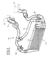
- FIG. 1 a circuit 10 for supplying an air intake manifold of a motor vehicle engine, schematically represented by the reference 16, in compressed air supplied by a turbocharger schematically represented by reference numeral 18.
- the circuit 10 comprises an input branch or conduit 12 which is connected to the output of a collector of the turbocharger 18 and an output branch or conduit 14 which is connected to the inlet of the intake manifold 16 of the motor.
- the circuit 10 also comprises a first branch 20, interposed between the turbocharger 18 and the collector 16, in which the air circulates through an air / air exchanger 22, for cooling the air circulating in said first branch 20, and a second branch 24, interposed between the turbocharger 18 and the collector 16, wherein the air flows directly to its outlet temperature of the turbocharger 18.
- the circuit 10 comprises a first housing 26, interposed upstream of the second branch 24, which comprises an inner flap (not shown) which is capable of progressively closing the second branch 24 to distribute the air flow between the two branches 20 and 24.
- the circuit also comprises a second housing 28, interposed downstream of the first branch 20, which is able to progressively close the first branch 20 to distribute the flow of air. air between the two branches 20 and 24.
- the two housings 26 and 28 are synchronized inversely from one another in opening and closing, so that a flap of a housing 26, 28 is open when that of the other housing is closed, and vice versa.
- the air supplied to the intake manifold 16 may not be adjusted to the required temperature, thus penalizing the operation of the engine.
- the two housings 26 and 28 can close the circuit, thus depriving the intake manifold 16 of air and interrupting the operation of the engine.
- FIG. 2 a circuit of the type of circuit 10 described has been proposed previously, comprising a mixer 30, interposed between the first and second branches 20, 24 and the intake manifold 16.
- This mixer 30 comprises a body 34 essentially comprising a main duct 36 which is intended to be connected to the intake manifold 16.
- This main duct is pierced with two parallel openings 38 and 40 inside which are mounted around the same axis 42 two butterflies 44 and 46 angularly offset by 90 ° relative to each other.
- Each of the openings 38 or 40 is connected to an associated branch 20 or 24 of the circuit 10 as previously shown, so that the flow of air coming from the branch 20 is inversely synchronized with the flow of air coming from the branch 24, which makes it possible to mix the air coming from the first and second branches 20, 24 in determined proportions to give a determined temperature to the air admitted into the intake manifold.
- Both butterflies are actuated by a single pneumatic actuator 48, a rod 50 drives the axis 42 via a spreader bar 52.
- This design allows reliable synchronization of butterflies 44 and 46, but is very cumbersome.
- the invention proposes a mixer 30 of the type of the one which has been shown in FIG. figure 3 .
- the mixer 30 comprises a first duct 54 and a second duct 56 of axes "A" and "B" associated secant, intended to be each connected to the first or second branch 20, 24 associated and jumping into a third conduit 58 to be connected to the manifold 16 intake.
- the first duct 54 and the second duct 56 each comprise, at their junction with the third duct 58, associated means 60, 62 for progressive closure, the progressive closing means of the first and second conduits 54, 56 being inversely synchronized with one another and actuated by a common control means 64.
- each means 60, 62 of progressive closure of each first / second conduit comprises a throttle 66, 68 of a diameter equal to that of the conduit 54, 56 associated and mounted to rotation about an axis 70, 72 diametral of said duct 54, 56.
- the shafts 70, 72 of the throttles 66, 68 of the first and second ducts 54, 56 pass through the first and second ducts 54, 56 and are each coupled to a associated rudder 74, 76, the pedals of the two ducts being connected by a common connecting rod 78 making it possible to keep constant a relative angular position of the butterflies 66, 68 according to which a throttle valve is closed 66, 68 when the throttle valve 68, 66 opposite is open, to synchronize the throttles 66, 68 inversely to each other.
- the common control means 64 consists of a means pneumatic control actuating the connecting rod 78 common.
- the pneumatic control means 64 comprises a housing 80 within which a membrane 82 delimits two opposed pressure chambers 84 and 86, at least one of which is capable of being subjected to a variable pressure to actuate the diaphragm 82 of which is secured to one end 88 of a rod 90 whose other end 92, projecting outside the housing 80, is coupled to the connecting rod 78.
- This design effectively ensures synchronization and control of the butterflies 66, 68.
- one of the first or second ducts 54, 56 for example here the second duct 56 is coaxial with the third duct 58 and the other, here the first duct 54 is perpendicular to the third duct 58.
- the butterflies 66, 68 are elastically biased towards a position in which the butterfly 66 of the first duct 54 associated with the first leg is open and in which the butterfly 68 of the second duct 56 is closed.
- This configuration makes it possible to guarantee that in the event of failure of the pneumatic control means 64, the third duct 58 supplies the air intake manifold 16 having passed through the air / air exchanger, since, in the event of impossibility of regulating the temperature of the intake air, it is preferable to supply the engine with cooled air rather than with hot air coming directly from the collector of the turbocharger 18.
- the butterfly 68 is for example returned to its closed position by a spiral spring (not shown) and the connection of the butterflies 66, 68 by the connecting rod 78 automatically returns the butterfly 66 to its open position.
- This configuration is obviously not limiting of the invention, and one could consider a configuration according to which the throttle 66 is elastically biased towards its open position, or a configuration in which the two throttles 66, 68 resiliently biased, the throttle 66 being biased towards its open position and the throttle valve 68 being biased towards its closed position, or a configuration according to which the connecting rod 78 is resiliently biased into an opening position of the throttle valve 66.
- the invention thus makes it possible to regulate in a simple and effective manner the temperature of the air admitted into an intake manifold of a turbocharged engine.
Landscapes
- Engineering & Computer Science (AREA)
- Physics & Mathematics (AREA)
- Thermal Sciences (AREA)
- Chemical & Material Sciences (AREA)
- Combustion & Propulsion (AREA)
- Mechanical Engineering (AREA)
- General Engineering & Computer Science (AREA)
- Supercharger (AREA)
- Control Of Throttle Valves Provided In The Intake System Or In The Exhaust System (AREA)
- Cooling, Air Intake And Gas Exhaust, And Fuel Tank Arrangements In Propulsion Units (AREA)
Claims (7)
- Kreislauf (10) zur Versorgung eines Luftansaugkrümmers (16) eines Verbrennungsmotors eines Kraftfahrzeugs mit Druckluft, die von einem Turbolader (18) geliefert wird, von der Art, die mindestens aufweist:- einen ersten Zweig (20), der zwischen den Turbolader (18) und den Krümmer (16) eingefügt ist, in dem die Luft durch einen Luft/Luft-Wärmetauscher (22) fließt, um die Kühlung der im ersten Zweig (20) fließenden Luft zu gewährleisten,- einen zweiten Zweig (24), der zwischen den Turbolader (18) und den Krümmer (16) eingefügt ist, in dem die Luft direkt auf ihrer Ausgangstemperatur aus dem Turbolader (18) fließt, und von der Art, die einen zwischen den ersten und den zweiten Zweig (20, 24) und den Ansaugkrümmer (16) eingefügten Mischer (30) aufweist, der dazu bestimmt ist, die vom ersten und zweiten Zweig (20, 24) kommende Luft gemäß bestimmten Anteilen zu mischen, um der in den Ansaugkrümmer (16) angesaugten Luft eine bestimmte Temperatur zu verleihen, wobei der Mischer (30) aufweist- einen ersten und einen zweiten Kanal (54, 56) mit sich schneidenden Achsen (A, B), die dazu bestimmt sind, jeder mit dem zugeordneten ersten (20) oder zweiten Zweig (24) verbunden zu werden und in einen dritten Kanal (58) münden, der dazu bestimmt ist, mit dem Ansaugkrümmer (16) verbunden zu werden,- und der erste und der zweite Kanal (54, 56) je an ihrer Verbindung mit dem dritten Kanal (58) Einrichtungen (60, 62) zum progressiven Verschluss aufweisen,
dadurch gekennzeichnet, dass- diese Einrichtungen zum progressiven Verschluss Drosselklappen (66, 68) enthalten, die umgekehrt zueinander synchronisiert sind und es ermöglichen, eine relative Winkelstellung der Drosselklappen (66, 68) konstant zu halten, und von einer gemeinsamen Steuereinrichtung (64) betätigt werden, gemäß der eine Drosselklappe (66, 68) geschlossen ist, wenn die andere Drosselklappe (66, 68) offen ist. - Kreislauf (10) nach dem vorhergehenden Anspruch, dadurch gekennzeichnet, dass die Drosselklappen (66, 68) einen Durchmesser gleich demjenigen ihres Kanals (54, 56) haben und um eine diametrale Achse (70, 72) von diesem drehbar montiert sind.
- Kreislauf (10) nach dem vorhergehenden Anspruch, dadurch gekennzeichnet, dass die Achsen (70, 72) der Drosselklappen (66, 68) des ersten und zweiten Kanals (54, 56) den ersten und zweiten Kanal (54, 56) durchqueren und je mit einem zugeordneten Schwinghebel (74, 76) gekoppelt sind, wobei die Schwinghebel (74, 76) der zwei Kanäle (54, 56) durch eine gemeinsame Schubstange (78) verbunden sind, die es ermöglicht, eine relative Winkelstellung der Drosselklappen (66, 68) konstant zu halten.
- Kreislauf (10) nach dem vorhergehenden Anspruch, dadurch gekennzeichnet, dass die gemeinsame Steuereinrichtung (64) aus einer pneumatischen Steuereinrichtung besteht, die die gemeinsame Schubstange betätigt.
- Kreislauf nach dem vorhergehenden Anspruch, dadurch gekennzeichnet, dass die pneumatische Steuereinrichtung (64) ein Gehäuse (80) aufweist, in dessen Innerem eine Membran (82) zwei Druckkammern (84, 86) begrenzt, von denen mindestens eine einem variablen Druck ausgesetzt sein kann, um die Membran (82) zu betätigen, mit der ein Ende (88) einer Stange (90) fest verbunden ist, deren anderes Ende (93), das aus dem Gehäuse (80) vorsteht, mit der Schubstange (78) gekoppelt ist.
- Kreislauf nach einem der Ansprüche 1 bis 5, dadurch gekennzeichnet, dass einer, der erste oder der zweite Kanal (54, 56), mit dem dritten Kanal (58) koaxial ist, und dass der andere zum dritten Kanal (58) lotrecht ist.
- Kreislauf nach einem der Ansprüche 2 bis 6, dadurch gekennzeichnet, dass die Drosselklappen (66, 68) elastisch in eine Stellung zurückgeholt werden, in der die Drosselklappe (66) des ersten Kanals (54) offen und die Drosselklappe (68) des zweiten Kanals (56) geschlossen ist.
Applications Claiming Priority (2)
| Application Number | Priority Date | Filing Date | Title |
|---|---|---|---|
| FR0310479 | 2003-09-04 | ||
| FR0310479A FR2859504B1 (fr) | 2003-09-04 | 2003-09-04 | Circuit pour l'alimentation d'un collecteur d'admission d'air d'un moteur thermique de vehicule automobile |
Publications (3)
| Publication Number | Publication Date |
|---|---|
| EP1512853A2 EP1512853A2 (de) | 2005-03-09 |
| EP1512853A3 EP1512853A3 (de) | 2010-05-19 |
| EP1512853B1 true EP1512853B1 (de) | 2012-09-05 |
Family
ID=34130753
Family Applications (1)
| Application Number | Title | Priority Date | Filing Date |
|---|---|---|---|
| EP04300486A Expired - Lifetime EP1512853B1 (de) | 2003-09-04 | 2004-07-28 | Zufuhrkreis für den Luftansaugkrümmer einer Fahrzeugbrennkraftmaschine |
Country Status (2)
| Country | Link |
|---|---|
| EP (1) | EP1512853B1 (de) |
| FR (1) | FR2859504B1 (de) |
Families Citing this family (10)
| Publication number | Priority date | Publication date | Assignee | Title |
|---|---|---|---|---|
| GB0622554D0 (en) * | 2006-11-14 | 2006-12-20 | Delphi Tech Inc | Bypass assembly for a charge-air cooler |
| FR2916524B1 (fr) * | 2007-05-24 | 2014-10-24 | Valeo Systemes Thermiques | Dispositif de regulation de la circulation d'un fluide dans un echangeur de chaleur,et module d'admission d'air associe |
| FR2925610B1 (fr) * | 2007-12-19 | 2014-03-28 | Valeo Sys Controle Moteur Sas | Vanne pour systeme d'admission d'air de moteur thermique |
| DE102010011372A1 (de) | 2009-04-17 | 2010-10-21 | Behr Gmbh & Co. Kg | Ladeluftkanal für einen Verbrennungsmotor |
| CN102425487B (zh) * | 2011-11-23 | 2013-12-25 | 段家忠 | 无增压内燃机中央冷却器 |
| FR2984960B1 (fr) | 2011-12-21 | 2013-12-20 | Valeo Sys Controle Moteur Sas | Doseur deux voies avec dosage sur chaque voie |
| USD971261S1 (en) * | 2020-10-16 | 2022-11-29 | Resource Intl Inc. | Intercooler pipes for automotive applications |
| USD957465S1 (en) * | 2020-10-16 | 2022-07-12 | Resource Intl Inc. | Intercooler for automotive applications |
| USD956819S1 (en) * | 2021-01-08 | 2022-07-05 | Resource Intl Inc. | Intercooler pipe for automotive applications |
| USD957461S1 (en) * | 2021-01-11 | 2022-07-12 | Resource Intl Inc. | Intercooler for automotive applications |
Family Cites Families (5)
| Publication number | Priority date | Publication date | Assignee | Title |
|---|---|---|---|---|
| JPS597542Y2 (ja) * | 1979-10-24 | 1984-03-08 | 日産自動車株式会社 | 過給機付内燃機関の吸気装置 |
| SE460304B (sv) * | 1981-12-01 | 1989-09-25 | Volvo Ab | Anordning foer tillfoersel av foerbraenningsluft till cylindrarna i en foerbraenningsmotor |
| DE4242010A1 (de) * | 1992-12-12 | 1994-06-16 | Man Nutzfahrzeuge Ag | Verfahren zur Regelung der Ladelufttemperatur, sowie Vorrichtung zu dessen Durchführung |
| FR2710953B1 (fr) * | 1993-10-05 | 1995-12-08 | Renault Vehicules Ind | Procédé et dispositif de commande d'un fluide traversant un boîtier de dérivation et système équipé d'un tel dispositif pour réguler l'air de suralimentation d'un moteur à combustion interne. |
| DE10130065A1 (de) * | 2001-06-21 | 2003-01-02 | Deutz Ag | Aufgeladene Brennkraftmaschine |
-
2003
- 2003-09-04 FR FR0310479A patent/FR2859504B1/fr not_active Expired - Fee Related
-
2004
- 2004-07-28 EP EP04300486A patent/EP1512853B1/de not_active Expired - Lifetime
Also Published As
| Publication number | Publication date |
|---|---|
| EP1512853A3 (de) | 2010-05-19 |
| FR2859504A1 (fr) | 2005-03-11 |
| EP1512853A2 (de) | 2005-03-09 |
| FR2859504B1 (fr) | 2006-02-24 |
Similar Documents
| Publication | Publication Date | Title |
|---|---|---|
| EP2859200B1 (de) | Abgaswärmerückgewinnungssystem | |
| EP1512853B1 (de) | Zufuhrkreis für den Luftansaugkrümmer einer Fahrzeugbrennkraftmaschine | |
| EP1567754B1 (de) | Verbesserte vorrichtung zur thermischen regelung von der ansaugluft einer brennkraftmaschine und rückgeführtem brennkraftmaschinenabgas | |
| FR2894315A1 (fr) | Vanne comportant des moyens d'actionnement entre deux conduits de sortie. | |
| FR2908833A1 (fr) | Dispositif d'admission de gaz | |
| WO2018002037A1 (fr) | Dispositif et methode de controle de l'introduction d'air et de gaz d'echappement a l'admission d'un moteur a combustion interne suralimente | |
| EP3491225A1 (de) | Vorrichtung und verfahren zur steuerung der kombinierten injektion von luft und abgasen am einlass eines aufgeladenen verbrennungsmotors | |
| FR2661947A1 (fr) | Procede et structure pour faire fonctionner automatiquement une vanne de dilution dans un turboreacteur a double flux. | |
| CN103459907A (zh) | 用于操纵调节阀的装置 | |
| FR2930296A1 (fr) | Ligne d'echappement avec un conduit de recyclage des gaz d'echappement muni d'un echangeur de recuperation de chaleur. | |
| EP1658419A1 (de) | Vorrichtung zur wärmeregelung von abgas | |
| EP1277605B2 (de) | Heizungs- und Klimaanlage mit einer Luftmischklappe | |
| EP3019922B1 (de) | Gasmischpumpe, insbesondere für eine heizungsanlage | |
| FR2872862A1 (fr) | Dispositif de commande pour un circuit de recirculation de gaz d'echappement d'un moteur a combustion interne | |
| WO2013171393A1 (fr) | Systeme de recuperation d'energie dans un circuit de gaz d'echappement | |
| EP2058487B1 (de) | Lader für Wärmekraftmotor, der mit einem Verteilergehäuse für die Ladeluft ausgestattet ist | |
| FR2859238A1 (fr) | Dispositif de regulation thermique de gaz d'echappement | |
| WO2004067931A1 (en) | A three-way valve, in particular a valve for a turbocharger system | |
| FR2806448A1 (fr) | Dispositif d'obturation et de regulation du debit de gaz d'echappement dans une ligne de recyclage de gaz d'echappement connectee a une ligne d'admission d'air d'un moteur a combustion interne | |
| FR2856426A1 (fr) | Circuit de refroidissement comportant un organe de regulation du flux | |
| EP3494298B1 (de) | Intercooler für eine aufgeladene brennkraftmaschine und zugeordnete aufladungskreis | |
| FR2491146A1 (fr) | Dispositif de reglage du debit du carburant pour divers types de moteurs a turbine a gaz | |
| FR3064674A1 (fr) | Dispositif de gestion thermique d’un groupe motopropulseur de vehicule | |
| EP0518725A1 (de) | Auszugvorrichtung für Brennkraftmaschine | |
| EP1537310A1 (de) | Ansaugsystem für eine brennkraftmaschine mit turbolader |
Legal Events
| Date | Code | Title | Description |
|---|---|---|---|
| PUAI | Public reference made under article 153(3) epc to a published international application that has entered the european phase |
Free format text: ORIGINAL CODE: 0009012 |
|
| AK | Designated contracting states |
Kind code of ref document: A2 Designated state(s): AT BE BG CH CY CZ DE DK EE ES FI FR GB GR HU IE IT LI LU MC NL PL PT RO SE SI SK TR |
|
| AX | Request for extension of the european patent |
Extension state: AL HR LT LV MK |
|
| PUAL | Search report despatched |
Free format text: ORIGINAL CODE: 0009013 |
|
| AK | Designated contracting states |
Kind code of ref document: A3 Designated state(s): AT BE BG CH CY CZ DE DK EE ES FI FR GB GR HU IE IT LI LU MC NL PL PT RO SE SI SK TR |
|
| AX | Request for extension of the european patent |
Extension state: AL HR LT LV MK |
|
| 17P | Request for examination filed |
Effective date: 20100730 |
|
| AKX | Designation fees paid |
Designated state(s): DE FR GB |
|
| 17Q | First examination report despatched |
Effective date: 20110124 |
|
| GRAP | Despatch of communication of intention to grant a patent |
Free format text: ORIGINAL CODE: EPIDOSNIGR1 |
|
| GRAS | Grant fee paid |
Free format text: ORIGINAL CODE: EPIDOSNIGR3 |
|
| GRAA | (expected) grant |
Free format text: ORIGINAL CODE: 0009210 |
|
| AK | Designated contracting states |
Kind code of ref document: B1 Designated state(s): DE FR GB |
|
| REG | Reference to a national code |
Ref country code: GB Ref legal event code: FG4D Free format text: NOT ENGLISH |
|
| REG | Reference to a national code |
Ref country code: DE Ref legal event code: R096 Ref document number: 602004039199 Country of ref document: DE Effective date: 20121031 |
|
| PLBE | No opposition filed within time limit |
Free format text: ORIGINAL CODE: 0009261 |
|
| STAA | Information on the status of an ep patent application or granted ep patent |
Free format text: STATUS: NO OPPOSITION FILED WITHIN TIME LIMIT |
|
| 26N | No opposition filed |
Effective date: 20130606 |
|
| REG | Reference to a national code |
Ref country code: DE Ref legal event code: R097 Ref document number: 602004039199 Country of ref document: DE Effective date: 20130606 |
|
| GBPC | Gb: european patent ceased through non-payment of renewal fee |
Effective date: 20130728 |
|
| PG25 | Lapsed in a contracting state [announced via postgrant information from national office to epo] |
Ref country code: GB Free format text: LAPSE BECAUSE OF NON-PAYMENT OF DUE FEES Effective date: 20130728 |
|
| REG | Reference to a national code |
Ref country code: FR Ref legal event code: PLFP Year of fee payment: 12 |
|
| REG | Reference to a national code |
Ref country code: FR Ref legal event code: PLFP Year of fee payment: 13 |
|
| PGFP | Annual fee paid to national office [announced via postgrant information from national office to epo] |
Ref country code: DE Payment date: 20160722 Year of fee payment: 13 |
|
| PGFP | Annual fee paid to national office [announced via postgrant information from national office to epo] |
Ref country code: FR Payment date: 20160721 Year of fee payment: 13 |
|
| REG | Reference to a national code |
Ref country code: DE Ref legal event code: R119 Ref document number: 602004039199 Country of ref document: DE |
|
| REG | Reference to a national code |
Ref country code: FR Ref legal event code: ST Effective date: 20180330 |
|
| PG25 | Lapsed in a contracting state [announced via postgrant information from national office to epo] |
Ref country code: DE Free format text: LAPSE BECAUSE OF NON-PAYMENT OF DUE FEES Effective date: 20180201 |
|
| PG25 | Lapsed in a contracting state [announced via postgrant information from national office to epo] |
Ref country code: FR Free format text: LAPSE BECAUSE OF NON-PAYMENT OF DUE FEES Effective date: 20170731 |