EP1512843B1 - Method of assembling a gas turbine engine and rotor assembly - Google Patents
Method of assembling a gas turbine engine and rotor assembly Download PDFInfo
- Publication number
- EP1512843B1 EP1512843B1 EP04253920.5A EP04253920A EP1512843B1 EP 1512843 B1 EP1512843 B1 EP 1512843B1 EP 04253920 A EP04253920 A EP 04253920A EP 1512843 B1 EP1512843 B1 EP 1512843B1
- Authority
- EP
- European Patent Office
- Prior art keywords
- disk
- rotor
- discharge tube
- retainer
- shaft
- Prior art date
- Legal status (The legal status is an assumption and is not a legal conclusion. Google has not performed a legal analysis and makes no representation as to the accuracy of the status listed.)
- Expired - Fee Related
Links
Images

Classifications
-
- F—MECHANICAL ENGINEERING; LIGHTING; HEATING; WEAPONS; BLASTING
- F01—MACHINES OR ENGINES IN GENERAL; ENGINE PLANTS IN GENERAL; STEAM ENGINES
- F01D—NON-POSITIVE DISPLACEMENT MACHINES OR ENGINES, e.g. STEAM TURBINES
- F01D5/00—Blades; Blade-carrying members; Heating, heat-insulating, cooling or antivibration means on the blades or the members
- F01D5/02—Blade-carrying members, e.g. rotors
- F01D5/025—Fixing blade carrying members on shafts
-
- F—MECHANICAL ENGINEERING; LIGHTING; HEATING; WEAPONS; BLASTING
- F01—MACHINES OR ENGINES IN GENERAL; ENGINE PLANTS IN GENERAL; STEAM ENGINES
- F01D—NON-POSITIVE DISPLACEMENT MACHINES OR ENGINES, e.g. STEAM TURBINES
- F01D25/00—Component parts, details, or accessories, not provided for in, or of interest apart from, other groups
- F01D25/08—Cooling; Heating; Heat-insulation
-
- F—MECHANICAL ENGINEERING; LIGHTING; HEATING; WEAPONS; BLASTING
- F01—MACHINES OR ENGINES IN GENERAL; ENGINE PLANTS IN GENERAL; STEAM ENGINES
- F01D—NON-POSITIVE DISPLACEMENT MACHINES OR ENGINES, e.g. STEAM TURBINES
- F01D5/00—Blades; Blade-carrying members; Heating, heat-insulating, cooling or antivibration means on the blades or the members
- F01D5/02—Blade-carrying members, e.g. rotors
- F01D5/06—Rotors for more than one axial stage, e.g. of drum or multiple disc type; Details thereof, e.g. shafts, shaft connections
- F01D5/066—Connecting means for joining rotor-discs or rotor-elements together, e.g. by a central bolt, by clamps
-
- F—MECHANICAL ENGINEERING; LIGHTING; HEATING; WEAPONS; BLASTING
- F01—MACHINES OR ENGINES IN GENERAL; ENGINE PLANTS IN GENERAL; STEAM ENGINES
- F01D—NON-POSITIVE DISPLACEMENT MACHINES OR ENGINES, e.g. STEAM TURBINES
- F01D5/00—Blades; Blade-carrying members; Heating, heat-insulating, cooling or antivibration means on the blades or the members
- F01D5/12—Blades
- F01D5/14—Form or construction
- F01D5/147—Construction, i.e. structural features, e.g. of weight-saving hollow blades
-
- F—MECHANICAL ENGINEERING; LIGHTING; HEATING; WEAPONS; BLASTING
- F01—MACHINES OR ENGINES IN GENERAL; ENGINE PLANTS IN GENERAL; STEAM ENGINES
- F01D—NON-POSITIVE DISPLACEMENT MACHINES OR ENGINES, e.g. STEAM TURBINES
- F01D5/00—Blades; Blade-carrying members; Heating, heat-insulating, cooling or antivibration means on the blades or the members
- F01D5/12—Blades
- F01D5/28—Selecting particular materials; Particular measures relating thereto; Measures against erosion or corrosion
- F01D5/284—Selection of ceramic materials
-
- F—MECHANICAL ENGINEERING; LIGHTING; HEATING; WEAPONS; BLASTING
- F01—MACHINES OR ENGINES IN GENERAL; ENGINE PLANTS IN GENERAL; STEAM ENGINES
- F01D—NON-POSITIVE DISPLACEMENT MACHINES OR ENGINES, e.g. STEAM TURBINES
- F01D5/00—Blades; Blade-carrying members; Heating, heat-insulating, cooling or antivibration means on the blades or the members
- F01D5/30—Fixing blades to rotors; Blade roots ; Blade spacers
- F01D5/3084—Fixing blades to rotors; Blade roots ; Blade spacers the blades being made of ceramics
-
- F—MECHANICAL ENGINEERING; LIGHTING; HEATING; WEAPONS; BLASTING
- F05—INDEXING SCHEMES RELATING TO ENGINES OR PUMPS IN VARIOUS SUBCLASSES OF CLASSES F01-F04
- F05D—INDEXING SCHEME FOR ASPECTS RELATING TO NON-POSITIVE-DISPLACEMENT MACHINES OR ENGINES, GAS-TURBINES OR JET-PROPULSION PLANTS
- F05D2230/00—Manufacture
- F05D2230/20—Manufacture essentially without removing material
- F05D2230/21—Manufacture essentially without removing material by casting
-
- F—MECHANICAL ENGINEERING; LIGHTING; HEATING; WEAPONS; BLASTING
- F05—INDEXING SCHEMES RELATING TO ENGINES OR PUMPS IN VARIOUS SUBCLASSES OF CLASSES F01-F04
- F05D—INDEXING SCHEME FOR ASPECTS RELATING TO NON-POSITIVE-DISPLACEMENT MACHINES OR ENGINES, GAS-TURBINES OR JET-PROPULSION PLANTS
- F05D2230/00—Manufacture
- F05D2230/60—Assembly methods
Definitions
- This application relates generally to gas turbine engines and, more particularly, to gas turbine engine rotor assemblies.
- Compressor bleed air is often used as a source of cooling air for the turbine cooling circuit and is also used to purge cavities defined within the engine. More specifically, maintaining sufficient cooling air and purging of air cavities within the gas turbine engine may be critical to proper engine performance and component longevity. However, extracting cooling air from the compressor may affect overall gas turbine engine performance. Balanced with the need to adequately cool components is a desire to maintain high levels of operating efficiency, and as such, generally, because the temperature of air flowing through the compressor increases at each stage of the compressor, utilizing cooling air from the lowest allowable compressor stage results in a lower engine performance decrement as a result of such cooling air extraction.
- the compressor system may fail to provide purge air at a sufficient pressure, and as such hot gases may be still be ingested into the cavities. Over time, continued exposure to such temperature excursions may limit the useful life of components adjacent to the cavities.
- US 5,700,130 discloses a device for cooling a gas turbine rotor using air taken from a compressor and supplied to a turbine of the gas turbine through a common shaft.
- GB 2,049,818 A discloses a particle separator in a blade cooling system of a gas turbine engine.
- US 4,890,981 discloses a boltless blade retainer for preventing forward axial movement of rotor blades in a turbo-machine relative to a rotor disk.
- a method of assembling a gas turbine engine is provided in accordance with claim 1 herein.
- a rotor assembly for a gas turbine engine including a centerline axis of rotation is provided in accordance with claim 4 herein.
- Figure 1 is a schematic illustration of a gas turbine engine 10 including a gear box 12, a high pressure compressor 14, and a combustor 16.
- Engine 10 also includes a high pressure turbine 18 and a low pressure turbine 20.
- Gear box 12 and turbine 20 are coupled by a first shaft 24, and compressor 14 and turbine 18 are coupled by a second shaft 26. Accordingly, because shafts 24 and 26 are aligned substantially coaxially, each is rotatable about the same axis of rotation 28.
- the gas turbine engine is an LV100 available from General Electric Company, Cincinnati, Ohio.
- the highly compressed air is delivered to combustor 16.
- Airflow from combustor 16 drives turbines 18 and 20 before exiting gas turbine engine 10.
- Work done by turbine 20 is then transmitted to gearbox 12 by means of shaft 24 wherein the available work can then be used to drive a vehicle or generator.
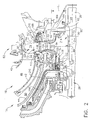
- FIG. 2 is a side cross-sectional schematic illustration of a turbine cooling circuit 38 that may be used with gas turbine engine 10.
- Combustor 16 includes an annular outer liner 40, an annular inner liner 42, and a domed end (not shown) extending between outer and inner liners 40 and 42, respectively.
- Outer liner 40 and inner liner 42 are spaced radially inward from a combustor casing (not shown) and define a combustion chamber system assembly 46.
- An inner nozzle support 44 is generally annular and extends downstream from a diffuser (not shown).
- Combustion chamber 46 is generally annular in shape and is defined between liners 40 and 42.
- Inner liner 42 and inner nozzle support 44 define an inner passageway 50.
- Outer and inner liners 40 and 42 each extend to a turbine nozzle 52 positioned downstream from combustor 16.
- High pressure turbine 18 is coupled substantially coaxially with compressor 14 (shown in Figure 1 ) and downstream from combustor 16.
- Turbine 18 includes a rotor assembly 62 that includes at least one rotor 64 that may be formed by one or more disks 66.
- disk 66 includes a radially outer rim 68, a radially inner hub 70, and an integral web 72 extending generally radially therebetween and radially inward from a respective blade dovetail slot 73.
- Each disk 66 also includes a plurality of blades 74 extending radially outward from outer rim 68. Disk 66 extends circumferentially around rotor assembly 62 and each row of blades 74 is sometimes referred to as a turbine stage.
- An annular forward disk retainer 80 and an annular aft disk retainer 82 extend along dovetail slot 73 to facilitate retaining rotor blades 74 within dovetail slot 73.
- forward disk retainer 80 extends along an upstream side 84 of disk 66 and includes a radially outer end 110, a radially inner end 112, and a body 114 extending therebetween.
- Body 114 includes a plurality of radially outer seal teeth 120 and a plurality of radially inner seal teeth 122.
- Radially outer seal teeth 120 cooperate with a seal member 124 to form an outer balance piston (OBP) seal 126
- radially inner seal teeth 122 cooperate with a seal member 128 to form an inner balance piston (IBP) seal 130.
- An accelerator discharge cavity 134 is defined between IBP seal 130 and OBP seal 126, and OBP seal 126 is positioned between cooling cavity 134 and an outer balance piston discharge cavity 138.
- Aft disk retainer 82 extends along a downstream side 150 of disk 66 and includes a radially outer end 152, a radially inner end 154, and a body 156 extending therebetween.
- Body 156 includes a cooling plate portion 160, a disk stub shaft portion 162, and a plurality of radial air pumpers 164 positioned therebetween.
- Cooling plate portion 160 is coupled against disk 66 with a radial interference fit and extends from retainer outer end 156 to each radial air pumper 164.
- Disk stub shaft portion 162 is oriented generally perpendicularly from retainer portion 160 and extends along rotor shaft 26.
- disk stub shaft portion 162 extends from radial air pumpers 164 to retainer end 154 to facilitate aft disk retainer 82 being coupled to shaft 26 such that a compressive load is induced through shaft portion 162 to retainer 82.
- Radial air pumpers 164 are spaced circumferentially within engine 10 and each is oriented substantially perpendicularly to axis of rotation 28.
- aft disk retainer 82 includes eight radial air pumpers 164.
- Each radial air pumper 164 is hollow and includes an inlet 180, an outlet 182 that is radially outward from inlet 182, and a substantially cylindrical body 184 extending therebetween.
- Each radial air pumper 164 has a length L 1 that enables each pumper 164 to extend at least partially into an aft rim cavity 188 bordered at least partially by aft disk retainer 82.
- radial air pumper length L 1 also facilitates maintaining or accelerating the angular air velocity of air flowing through pumpers 164, and increasing the discharge pressure of such air relative to a weaker forced vortex pressure rise which would occur without the use of pumpers 164.
- Each radial air pumper inlet 180 is coupled in flow communication with a bore cavity 190.
- Bore cavity 190 is defined at least partially between disk 66 and shaft 26.
- Bore cavity 190 extends radially between, and is coupled in flow communication to, each radial air pumper 164 and to a sump buffer cavity 194.
- Sump buffer cavity 194 is also coupled in flow communication to an air source through an annulus 196, such that air discharged from annulus 196 enters sump buffer cavity 194 prior to being discharged into a sump 200.
- leakage from sump buffer cavity 194 is channeled to bore cavity 190.
- Cooling circuit 38 is in flow communication with an air source, such as compressor 14 and turbine 20 and supplies cooling air from compressor 14 to facilitate cooling turbine 20.
- air discharged from compressor 14 is mixed with fuel and ignited to produce hot combustion gases.
- the resulting hot combustion gases drive turbine 20.
- a portion of air is extracted from compressor 14 to cooling circuit 38 to facilitate cooling turbine components and purging cavities.
- At least a portion of air extracted from compressor 14 is channeled through an accelerator prior to being discharged into accelerator discharge cavity 134. Cooling air 209 supplied from sump buffer cavity 194 is channeled into sump 200. A portion 212 of air 210 supplied to buffer cavity 194 is mixed with air 214 leaking from discharge cavity 134 through IBP seal 130 and is channeled into bore cavity 190. Leakage of air 212 from sump buffer cavity 194 facilitates preventing ingestion of warm compressor discharge air within sump 200. More specifically, because air 214 flowing into bore cavity 190 is discharged through pumpers 164, the operating pressure within bore cavity 190 is decreased, such that pumpers 164 facilitate positively purging cavity 190 and preventing flow 212 from reversing direction. Moreover, because the discharge pressure of air 214 flowing through pumpers 164 is increased, pumpers 164 also facilitate positively purging aft rim cavity 188.
- Flow 216 discharged from aft rim cavity 188 is forced radially outwardly between a disk seal assembly 82 and an aft transition duct inner flow path buffer seal 218 to facilitate cooling of outer rotor rim 68 and disk seal assembly 82.
- purging of cavities 190 and 188 facilitates preventing ingestion of warm compressor discharge therein, which over time, could cause damage to components housed within, adjacent to, or in flow communication with cavities 188 and 190.
- the above-described turbine cooling circuit is cost-effective and highly reliable.
- the cooling circuit includes an aft disk retainer that is formed integrally with a shaft stub portion and with a plurality of radial air pumpers. Because the retainer is formed integrally with a cooling plate portion and a disk stub portion, manufacturing costs, and turbine assembly times are facilitated to be reduced. Moreover, because the radial pumpers increase a discharge pressure of air flowing therethrough, the pumpers facilitate positively purging the aft rim cavity and the bore cavity thus ensuring purge flow from the sump buffer cavity. Accordingly, the pumpers thus facilitate preventing warm compressor dischrage from being ingested within the aforementioned cavities. As a result, the aft rotor retainer assembly and the cooling circuit facilitates extending a useful life of the turbine rotor assembly in a cost-effective and reliable manner.
- rotor assemblies and cooling circuits are described above in detail.
- the rotor assemblies are not limited to the specific embodiments described herein, but rather, components of each assembly may be utilized independently and separately from other components described herein.
- each aft retainer assembly component can also be used in combination with other cooling circuit components and with other rotor assemblies.
Landscapes
- Engineering & Computer Science (AREA)
- Mechanical Engineering (AREA)
- General Engineering & Computer Science (AREA)
- Chemical & Material Sciences (AREA)
- Ceramic Engineering (AREA)
- Architecture (AREA)
- Materials Engineering (AREA)
- Turbine Rotor Nozzle Sealing (AREA)
- Structures Of Non-Positive Displacement Pumps (AREA)
Applications Claiming Priority (2)
| Application Number | Priority Date | Filing Date | Title |
|---|---|---|---|
| US10/656,599 US6910852B2 (en) | 2003-09-05 | 2003-09-05 | Methods and apparatus for cooling gas turbine engine rotor assemblies |
| US656599 | 2003-09-05 |
Publications (3)
| Publication Number | Publication Date |
|---|---|
| EP1512843A2 EP1512843A2 (en) | 2005-03-09 |
| EP1512843A3 EP1512843A3 (en) | 2012-03-14 |
| EP1512843B1 true EP1512843B1 (en) | 2016-03-09 |
Family
ID=34136709
Family Applications (1)
| Application Number | Title | Priority Date | Filing Date |
|---|---|---|---|
| EP04253920.5A Expired - Fee Related EP1512843B1 (en) | 2003-09-05 | 2004-06-30 | Method of assembling a gas turbine engine and rotor assembly |
Country Status (5)
| Country | Link |
|---|---|
| US (1) | US6910852B2 (pt) |
| EP (1) | EP1512843B1 (pt) |
| JP (1) | JP4559141B2 (pt) |
| CN (1) | CN100404816C (pt) |
| BR (1) | BRPI0402669A (pt) |
Families Citing this family (27)
| Publication number | Priority date | Publication date | Assignee | Title |
|---|---|---|---|---|
| DE102005027890B4 (de) * | 2005-06-16 | 2007-05-03 | Man Diesel Se | Abgasturbolader für eine Brennkraftmaschine |
| FR2892454B1 (fr) * | 2005-10-21 | 2008-01-25 | Snecma Sa | Dispositif de ventilation de disques de turbine dans un moteur a turbine a gaz |
| US7458774B2 (en) * | 2005-12-20 | 2008-12-02 | General Electric Company | High pressure turbine disk hub with curved hub surface and method |
| US8016552B2 (en) * | 2006-09-29 | 2011-09-13 | General Electric Company | Stator—rotor assemblies having surface features for enhanced containment of gas flow, and related processes |
| US20080080972A1 (en) * | 2006-09-29 | 2008-04-03 | General Electric Company | Stationary-rotating assemblies having surface features for enhanced containment of fluid flow, and related processes |
| US7967559B2 (en) * | 2007-05-30 | 2011-06-28 | General Electric Company | Stator-rotor assembly having surface feature for enhanced containment of gas flow and related processes |
| US8506660B2 (en) * | 2007-09-12 | 2013-08-13 | General Electric Company | Nozzles for use with gasifiers and methods of assembling the same |
| US8240974B2 (en) * | 2008-03-21 | 2012-08-14 | United Technologies Corporation | Cold air buffer supply tube |
| JP4929217B2 (ja) * | 2008-03-28 | 2012-05-09 | 三菱重工業株式会社 | ガスタービンおよびガスタービンの中間軸ならびにガスタービン圧縮機の冷却方法 |
| US8277170B2 (en) * | 2008-05-16 | 2012-10-02 | General Electric Company | Cooling circuit for use in turbine bucket cooling |
| GB201015028D0 (en) * | 2010-09-10 | 2010-10-20 | Rolls Royce Plc | Gas turbine engine |
| US8740554B2 (en) | 2011-01-11 | 2014-06-03 | United Technologies Corporation | Cover plate with interstage seal for a gas turbine engine |
| US8662845B2 (en) | 2011-01-11 | 2014-03-04 | United Technologies Corporation | Multi-function heat shield for a gas turbine engine |
| US8840375B2 (en) | 2011-03-21 | 2014-09-23 | United Technologies Corporation | Component lock for a gas turbine engine |
| ITCO20110013A1 (it) | 2011-03-29 | 2012-09-30 | Nuovo Pignone Spa | Sistemi di chiusura per turboespansori da usare in cicli rankine organici |
| US9062566B2 (en) * | 2012-04-02 | 2015-06-23 | United Technologies Corporation | Turbomachine thermal management |
| US9234463B2 (en) | 2012-04-24 | 2016-01-12 | United Technologies Corporation | Thermal management system for a gas turbine engine |
| CN203665072U (zh) * | 2012-12-26 | 2014-06-25 | 浙江金浪动力有限公司 | 一种多功能发动机装配台 |
| CN103056653B (zh) * | 2013-01-11 | 2015-12-02 | 沈阳黎明航空发动机(集团)有限责任公司 | 一种托架式核心机装配方法 |
| EP2787169A1 (de) * | 2013-04-04 | 2014-10-08 | MTU Aero Engines GmbH | Rotor für eine Strömungsmaschine |
| CN103899367B (zh) * | 2014-02-14 | 2015-07-29 | 哈尔滨工业大学 | 航空发动机转子堆叠装配方法与装置 |
| CN103790651B (zh) * | 2014-02-14 | 2015-07-29 | 哈尔滨工业大学 | 气浮与磁浮相结合的航空发动机转子装配方法与装置 |
| US10316681B2 (en) * | 2016-05-31 | 2019-06-11 | General Electric Company | System and method for domestic bleed circuit seals within a turbine |
| US10539035B2 (en) * | 2017-06-29 | 2020-01-21 | General Electric Company | Compliant rotatable inter-stage turbine seal |
| US10947993B2 (en) | 2017-11-27 | 2021-03-16 | General Electric Company | Thermal gradient attenuation structure to mitigate rotor bow in turbine engine |
| US11674395B2 (en) * | 2020-09-17 | 2023-06-13 | General Electric Company | Turbomachine rotor disk with internal bore cavity |
| US11879411B2 (en) | 2022-04-07 | 2024-01-23 | General Electric Company | System and method for mitigating bowed rotor in a gas turbine engine |
Family Cites Families (18)
| Publication number | Priority date | Publication date | Assignee | Title |
|---|---|---|---|---|
| US4086757A (en) * | 1976-10-06 | 1978-05-02 | Caterpillar Tractor Co. | Gas turbine cooling system |
| US4190398A (en) * | 1977-06-03 | 1980-02-26 | General Electric Company | Gas turbine engine and means for cooling same |
| US4309147A (en) * | 1979-05-21 | 1982-01-05 | General Electric Company | Foreign particle separator |
| US4541774A (en) * | 1980-05-01 | 1985-09-17 | General Electric Company | Turbine cooling air deswirler |
| FR2732405B1 (fr) * | 1982-03-23 | 1997-05-30 | Snecma | Dispositif pour refroidir le rotor d'une turbine a gaz |
| US4882902A (en) * | 1986-04-30 | 1989-11-28 | General Electric Company | Turbine cooling air transferring apparatus |
| US4890981A (en) * | 1988-12-30 | 1990-01-02 | General Electric Company | Boltless rotor blade retainer |
| US5472313A (en) | 1991-10-30 | 1995-12-05 | General Electric Company | Turbine disk cooling system |
| US5275534A (en) | 1991-10-30 | 1994-01-04 | General Electric Company | Turbine disk forward seal assembly |
| US5226785A (en) * | 1991-10-30 | 1993-07-13 | General Electric Company | Impeller system for a gas turbine engine |
| US5236302A (en) | 1991-10-30 | 1993-08-17 | General Electric Company | Turbine disk interstage seal system |
| US5288210A (en) | 1991-10-30 | 1994-02-22 | General Electric Company | Turbine disk attachment system |
| US5555721A (en) | 1994-09-28 | 1996-09-17 | General Electric Company | Gas turbine engine cooling supply circuit |
| JP3448145B2 (ja) * | 1995-11-24 | 2003-09-16 | 三菱重工業株式会社 | 熱回収式ガスタービンロータ |
| US5755556A (en) * | 1996-05-17 | 1998-05-26 | Westinghouse Electric Corporation | Turbomachine rotor with improved cooling |
| JPH10238301A (ja) * | 1997-02-21 | 1998-09-08 | Mitsubishi Heavy Ind Ltd | ガスタービン翼の冷却通路 |
| US6331097B1 (en) * | 1999-09-30 | 2001-12-18 | General Electric Company | Method and apparatus for purging turbine wheel cavities |
| US6398487B1 (en) * | 2000-07-14 | 2002-06-04 | General Electric Company | Methods and apparatus for supplying cooling airflow in turbine engines |
-
2003
- 2003-09-05 US US10/656,599 patent/US6910852B2/en not_active Expired - Lifetime
-
2004
- 2004-06-30 EP EP04253920.5A patent/EP1512843B1/en not_active Expired - Fee Related
- 2004-07-02 BR BR0402669-1A patent/BRPI0402669A/pt not_active IP Right Cessation
- 2004-07-05 CN CNB2004100634658A patent/CN100404816C/zh active Active
- 2004-07-05 JP JP2004197762A patent/JP4559141B2/ja not_active Expired - Fee Related
Also Published As
| Publication number | Publication date |
|---|---|
| CN100404816C (zh) | 2008-07-23 |
| BRPI0402669A (pt) | 2005-05-24 |
| JP4559141B2 (ja) | 2010-10-06 |
| EP1512843A2 (en) | 2005-03-09 |
| EP1512843A3 (en) | 2012-03-14 |
| JP2005083375A (ja) | 2005-03-31 |
| US6910852B2 (en) | 2005-06-28 |
| US20050053464A1 (en) | 2005-03-10 |
| CN1590733A (zh) | 2005-03-09 |
Similar Documents
| Publication | Publication Date | Title |
|---|---|---|
| EP1512843B1 (en) | Method of assembling a gas turbine engine and rotor assembly | |
| US20180328187A1 (en) | Turbine engine with an airfoil and insert | |
| US8087249B2 (en) | Turbine cooling air from a centrifugal compressor | |
| JP4610710B2 (ja) | タービンホイール空洞をパージする方法と装置 | |
| US7114339B2 (en) | Cavity on-board injection for leakage flows | |
| CA2784315C (en) | Aircraft gas turbine | |
| CA2728958C (en) | Cooled turbine rim seal | |
| US7344354B2 (en) | Methods and apparatus for operating gas turbine engines | |
| EP3090163B1 (en) | Compressor rim thermal management | |
| CN111927628B (zh) | 用于涡轮机的热交换器 | |
| JP2019056368A (ja) | ガスタービンエンジン用の空気送達システム | |
| WO2014047022A1 (en) | Gas turbine engine component cooling circuit | |
| JP2012013080A (ja) | ガスタービンエンジンに用いるロータ組立体、およびそれを組み立てる方法 | |
| US10539035B2 (en) | Compliant rotatable inter-stage turbine seal | |
| CN110005530B (zh) | 燃气涡轮发动机中的压缩机冷却 | |
| US20190218925A1 (en) | Turbine engine shroud | |
| CN111594275B (zh) | 具有气流管理组件的涡轮机 | |
| US11377957B2 (en) | Gas turbine engine with a diffuser cavity cooled compressor | |
| US11248481B2 (en) | Turbine vane having dual source cooling | |
| CN114718656A (zh) | 用于控制燃气涡轮发动机内的叶片间隙的系统 | |
| EP2771554B1 (en) | Gas turbine and method for guiding compressed fluid in a gas turbine | |
| CN117988985A (zh) | 用于燃气涡轮发动机的空气导向件 | |
| GB2356671A (en) | Gas turbine engine cooling |
Legal Events
| Date | Code | Title | Description |
|---|---|---|---|
| PUAI | Public reference made under article 153(3) epc to a published international application that has entered the european phase |
Free format text: ORIGINAL CODE: 0009012 |
|
| AK | Designated contracting states |
Kind code of ref document: A2 Designated state(s): AT BE BG CH CY CZ DE DK EE ES FI FR GB GR HU IE IT LI LU MC NL PL PT RO SE SI SK TR |
|
| AX | Request for extension of the european patent |
Extension state: AL HR LT LV MK |
|
| PUAL | Search report despatched |
Free format text: ORIGINAL CODE: 0009013 |
|
| AK | Designated contracting states |
Kind code of ref document: A3 Designated state(s): AT BE BG CH CY CZ DE DK EE ES FI FR GB GR HU IE IT LI LU MC NL PL PT RO SE SI SK TR |
|
| AX | Request for extension of the european patent |
Extension state: AL HR LT LV MK |
|
| RIC1 | Information provided on ipc code assigned before grant |
Ipc: F01D 25/08 20060101AFI20120206BHEP Ipc: F01D 5/30 20060101ALI20120206BHEP Ipc: F01D 5/06 20060101ALI20120206BHEP Ipc: F01D 5/14 20060101ALI20120206BHEP Ipc: F01D 5/02 20060101ALI20120206BHEP Ipc: F01D 5/28 20060101ALI20120206BHEP |
|
| 17P | Request for examination filed |
Effective date: 20120914 |
|
| AKX | Designation fees paid |
Designated state(s): DE FR GB IT SE |
|
| 17Q | First examination report despatched |
Effective date: 20130207 |
|
| GRAP | Despatch of communication of intention to grant a patent |
Free format text: ORIGINAL CODE: EPIDOSNIGR1 |
|
| INTG | Intention to grant announced |
Effective date: 20150922 |
|
| GRAS | Grant fee paid |
Free format text: ORIGINAL CODE: EPIDOSNIGR3 |
|
| GRAA | (expected) grant |
Free format text: ORIGINAL CODE: 0009210 |
|
| AK | Designated contracting states |
Kind code of ref document: B1 Designated state(s): DE FR GB IT SE |
|
| REG | Reference to a national code |
Ref country code: GB Ref legal event code: FG4D |
|
| REG | Reference to a national code |
Ref country code: DE Ref legal event code: R096 Ref document number: 602004048753 Country of ref document: DE |
|
| REG | Reference to a national code |
Ref country code: FR Ref legal event code: PLFP Year of fee payment: 13 |
|
| PG25 | Lapsed in a contracting state [announced via postgrant information from national office to epo] |
Ref country code: SE Free format text: LAPSE BECAUSE OF FAILURE TO SUBMIT A TRANSLATION OF THE DESCRIPTION OR TO PAY THE FEE WITHIN THE PRESCRIBED TIME-LIMIT Effective date: 20160309 |
|
| REG | Reference to a national code |
Ref country code: DE Ref legal event code: R097 Ref document number: 602004048753 Country of ref document: DE |
|
| PG25 | Lapsed in a contracting state [announced via postgrant information from national office to epo] |
Ref country code: IT Free format text: LAPSE BECAUSE OF FAILURE TO SUBMIT A TRANSLATION OF THE DESCRIPTION OR TO PAY THE FEE WITHIN THE PRESCRIBED TIME-LIMIT Effective date: 20160309 |
|
| PLBE | No opposition filed within time limit |
Free format text: ORIGINAL CODE: 0009261 |
|
| STAA | Information on the status of an ep patent application or granted ep patent |
Free format text: STATUS: NO OPPOSITION FILED WITHIN TIME LIMIT |
|
| 26N | No opposition filed |
Effective date: 20161212 |
|
| REG | Reference to a national code |
Ref country code: FR Ref legal event code: PLFP Year of fee payment: 14 |
|
| PGFP | Annual fee paid to national office [announced via postgrant information from national office to epo] |
Ref country code: GB Payment date: 20170627 Year of fee payment: 14 Ref country code: FR Payment date: 20170627 Year of fee payment: 14 |
|
| PGFP | Annual fee paid to national office [announced via postgrant information from national office to epo] |
Ref country code: DE Payment date: 20170628 Year of fee payment: 14 |
|
| REG | Reference to a national code |
Ref country code: DE Ref legal event code: R119 Ref document number: 602004048753 Country of ref document: DE |
|
| GBPC | Gb: european patent ceased through non-payment of renewal fee |
Effective date: 20180630 |
|
| PG25 | Lapsed in a contracting state [announced via postgrant information from national office to epo] |
Ref country code: FR Free format text: LAPSE BECAUSE OF NON-PAYMENT OF DUE FEES Effective date: 20180630 Ref country code: DE Free format text: LAPSE BECAUSE OF NON-PAYMENT OF DUE FEES Effective date: 20190101 Ref country code: GB Free format text: LAPSE BECAUSE OF NON-PAYMENT OF DUE FEES Effective date: 20180630 |