EP1512836B1 - Turbinenschaufelanordnung und ihr montageverfahren - Google Patents
Turbinenschaufelanordnung und ihr montageverfahren Download PDFInfo
- Publication number
- EP1512836B1 EP1512836B1 EP02733416.8A EP02733416A EP1512836B1 EP 1512836 B1 EP1512836 B1 EP 1512836B1 EP 02733416 A EP02733416 A EP 02733416A EP 1512836 B1 EP1512836 B1 EP 1512836B1
- Authority
- EP
- European Patent Office
- Prior art keywords
- turbine rotor
- rotor blades
- blades
- top plate
- assembly
- Prior art date
- Legal status (The legal status is an assumption and is not a legal conclusion. Google has not performed a legal analysis and makes no representation as to the accuracy of the status listed.)
- Expired - Lifetime
Links
- 238000000034 method Methods 0.000 title claims description 10
- 125000006850 spacer group Chemical group 0.000 claims description 4
- 238000010586 diagram Methods 0.000 description 4
- 229920000535 Tan II Polymers 0.000 description 1
- 238000013016 damping Methods 0.000 description 1
- 230000000694 effects Effects 0.000 description 1
Images


Classifications
-
- F—MECHANICAL ENGINEERING; LIGHTING; HEATING; WEAPONS; BLASTING
- F01—MACHINES OR ENGINES IN GENERAL; ENGINE PLANTS IN GENERAL; STEAM ENGINES
- F01D—NON-POSITIVE DISPLACEMENT MACHINES OR ENGINES, e.g. STEAM TURBINES
- F01D5/00—Blades; Blade-carrying members; Heating, heat-insulating, cooling or antivibration means on the blades or the members
- F01D5/12—Blades
- F01D5/22—Blade-to-blade connections, e.g. for damping vibrations
- F01D5/225—Blade-to-blade connections, e.g. for damping vibrations by shrouding
-
- F—MECHANICAL ENGINEERING; LIGHTING; HEATING; WEAPONS; BLASTING
- F05—INDEXING SCHEMES RELATING TO ENGINES OR PUMPS IN VARIOUS SUBCLASSES OF CLASSES F01-F04
- F05D—INDEXING SCHEME FOR ASPECTS RELATING TO NON-POSITIVE-DISPLACEMENT MACHINES OR ENGINES, GAS-TURBINES OR JET-PROPULSION PLANTS
- F05D2220/00—Application
- F05D2220/30—Application in turbines
- F05D2220/31—Application in turbines in steam turbines
-
- F—MECHANICAL ENGINEERING; LIGHTING; HEATING; WEAPONS; BLASTING
- F05—INDEXING SCHEMES RELATING TO ENGINES OR PUMPS IN VARIOUS SUBCLASSES OF CLASSES F01-F04
- F05D—INDEXING SCHEME FOR ASPECTS RELATING TO NON-POSITIVE-DISPLACEMENT MACHINES OR ENGINES, GAS-TURBINES OR JET-PROPULSION PLANTS
- F05D2230/00—Manufacture
- F05D2230/60—Assembly methods
- F05D2230/64—Assembly methods using positioning or alignment devices for aligning or centring, e.g. pins
- F05D2230/644—Assembly methods using positioning or alignment devices for aligning or centring, e.g. pins for adjusting the position or the alignment, e.g. wedges or eccenters
-
- F—MECHANICAL ENGINEERING; LIGHTING; HEATING; WEAPONS; BLASTING
- F05—INDEXING SCHEMES RELATING TO ENGINES OR PUMPS IN VARIOUS SUBCLASSES OF CLASSES F01-F04
- F05D—INDEXING SCHEME FOR ASPECTS RELATING TO NON-POSITIVE-DISPLACEMENT MACHINES OR ENGINES, GAS-TURBINES OR JET-PROPULSION PLANTS
- F05D2250/00—Geometry
- F05D2250/30—Arrangement of components
- F05D2250/31—Arrangement of components according to the direction of their main axis or their axis of rotation
- F05D2250/314—Arrangement of components according to the direction of their main axis or their axis of rotation the axes being inclined in relation to each other
-
- F—MECHANICAL ENGINEERING; LIGHTING; HEATING; WEAPONS; BLASTING
- F05—INDEXING SCHEMES RELATING TO ENGINES OR PUMPS IN VARIOUS SUBCLASSES OF CLASSES F01-F04
- F05D—INDEXING SCHEME FOR ASPECTS RELATING TO NON-POSITIVE-DISPLACEMENT MACHINES OR ENGINES, GAS-TURBINES OR JET-PROPULSION PLANTS
- F05D2250/00—Geometry
- F05D2250/70—Shape
Definitions
- This invention relates to a turbine rotor blades assembly and a method for assembling the same.
- Heat energy of a working medium has been converted into mechanical energy via steam turbine systems in a heat power plant or a atomic power plant.
- Such a steam turbine system comprises a turbine casing, a plurality of sets of stator blades disposed longitudinally along the axis of the casing, and at least one set of turbine rotor blades fixed to the outer circumference of a turbine rotor such that the set of turbine rotor blades are disposed alternately with respect to the plurality of sets of stator blades, wherein each of the turbine rotor blades is supported rotatably around a longitudinal axis so as to rotate relative to the stator blades.
- Such a prior art system includes shrouds inserted into each one of a plurality of tenon portions formed at the top end portions of the turbine rotor blades and then fixedly attached to each of the turbine rotor blades by calking.
- This forms an interconnecting structure which enables each one of a plurality of turbine rotor blades to be fixedly attached to the outer circumference of a turbine rotor in an evenly spaced apart relationship.
- Such a interconnecting structure between top end portions of the turbine rotor blades not only prevents vibration of the turbine rotor blades, but also keeps a constant dimensional gap between the inner surface of the casing and the outer portion of the turbine rotor blades, thereby preventing leakage of hot steam gas through that gap.
- ISB Intelligent Shroud Blade
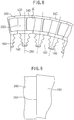
- FIGS. 7 to 11 illustrates a turbine rotor blades assembly according to the prior art ISB system.
- a turbine rotor blade 120 includes a platform 200 having a blade root portion 180 fixedly inserted into a disk 160 of a rotor 170, a profile member 220 extending radially outwardly from the platform 200, a top plate 240 formed integrally with the profile member 220, a plurality of these top plates 240 connecting adjacent top portions of a plurality of profile members 220 such that a plurality of turbine rotor blades 120 are combined circumferentially.
- the plurality of turbine rotor blades 120 are provided around the rotor 170 adjacent to each other in a circumferential direction.
- the top plate 240 includes end surfaces 260 providing a abutment relationship between two top plates 240, and these end surfaces 260 have a parallel relationship with respect to the straight line extending from the center of the rotor 170 to the center of the profile member 220.
- This ISB system like the shrouds calking system described above, reduces vibration and/or stress during operation, since a plurality of turbine rotor blades are fixedly interconnected due to the end surfaces 260 providing the abutment relationship between the top plates 240 of the turbine rotor blades, when the turbine rotor blades 120 are assembled by inserting the blade root portions 180 into the outer portion of the disk 160 of the rotor 170.
- the drawbacks of the ISB system are due to the fact that the abutting end surfaces of the two top plates are generally parallel with respect to the straight line extending from the center of the rotor to the center of the profile member.
- the pitch dimension will become enlarged significantly along the circumference of the disk due to a centrifugal force and thermal expansion during operation of the rotary blades.
- Such an expansion of the pitch dimension of the disk will also cause enlargement of the pitch dimension between top portions of adjacent turbine rotor blades in a circumferential direction, so that a clearance will occur between two adjacent end surfaces 260.
- two adjacent turbine rotor blades will overlap each other during assembling of the turbine rotor blades assembly, as shown in FIGS. 10 and 11 , which makes assembling difficult.
- one object of the present invention is to provide a turbine rotor blades assembly which can be assembled easily and also can maintain a securely fixed circumferential relationship between each two adjacent top portions of the turbine rotor blades during operation thereof.
- Another object of the present invention is to provide a method for assembling a turbine rotor blades assembly which can maintain a securely fixed circumferential relationship between each two adjacent top portions of the turbine rotor blades during operation thereof.
- US 5,511,948 A refers to a rotor blade damping structure for an axial-flow turbine.
- two contact surfaces of the shrouds are so formed to have mutual inclined angles with respect to each other.
- one of the shrouds of the blade is formed into a wedge shape converging in the axially frontward direction of the turbine, and the other shrouds of two adjacent blades are formed into a wedge shape converging in the axially rearward direction of the turbine.
- JP10339105 and US3545882 disclose a turbine rotor with rotor blades each one having a top plate providing abutment engaging surfaces between adjacent blades said surfaces being slantingly angled in the same circumferential direction.
- US 5.001 . 830 A discloses a method for assembling side entry control stage blades in a steam turbine.
- the present invention relates to a turbine rotor blades assembly according to claim 1.
- the turbine rotor blades are assembled onto the rotor by mounting each turbine rotor lade one by one onto the outer circumference of the rotor, while keeping the end surface of a top plate of a turbine rotor blade to be mounted abutted against the end surface of the top plate of the previously mounted turbine rotor blade.
- said slant angle is between 5° and 30°.
- the present invention also relates to a method for assembling the above mentioned turbine rotor blades assembly, comprising inserting root portions of turbine rotor blades into corresponding rotor disks one by one until all of the turbine rotor blades are fixedly attached upon corresponding rotor disks, comprising: inserting a spacer member between a platform of the turbine rotor blade to be attached and outer surface of the rotor at the side opposite from the previously fixed turbine rotor blade; biasing the turbine rotor blade to be attached during assembling thereof so as to provide abutment engagement between a top plate of the turbine rotor blade to be attached and a top plate of the turbine rotor blade previously fixed; repeating said inserting step and biasing step for each of the turbine rotor blades until all of the turbine rotor blades are installed.
- FIG. 1 illustrates a cross-sectional view of a turbine rotor blades assembly in accordance with the present invention when the assembly is in an operating state.
- FIG. 2 illustrates an enlarged detail view of the assembly, as taken within a circle II shown in FIG. 1 .
- FIG. 3 illustrates a cross-sectional view of a turbine rotor blades assembly in accordance with the present invention when the assembly is in an assembling state.
- FIG. 4 illustrates an enlarged detail view of the assembly, as taken within a circle IV shown in FIG. 3 .
- Turbine rotor blades assembly 10 includes, as in the prior art, a plurality of turbine rotor blades 12 attached to the outer circumference of a rotor.
- the number of the turbine rotor blades 12 is a matter of design.
- Each turbine rotor blade 12 includes a platform 20 having a blade root 18 fixedly inserted into the outer portion of a rotor disk 16, a profile member 22 extending radially outwardly from the platform 20, and a top plate 24 formed integrally with the profile member.
- the plurality of turbine rotor blades 12 are interconnected with each other in such a way that the plurality of turbine rotor blades are combined in a circumferential direction via engagement between each pair of adjacent top plates 24.
- abutment engaging surface 26 between adjacent turbine rotor blades 12 has a slanted angle ⁇ relative to a straight line extending from the center of the rotor to the center of the profile member 22, when turbine rotor blades 12 are attached around the rotor.
- this slanted angle is in the range of 5° to 30° , although it may be selected properly depending upon the possible dimension of the clearance between two adjacent end surfaces 26 of the top plates 24 under a centrifugal force and thermal expansion during operation.
- Each one of a plurality of turbine rotor blades may have a top plate having a circumferential length different from those of the other blades. Such a difference in circumferential length of each top plate may be selected so as to properly adjust the amount of outward relief of the top plates caused by a centrifugal force thereupon, thereby optimizing the abutment force between two adjacent end surfaces.
- the turbine rotor blades 12 are assembled to be attached around the rotor by mounting the turbine rotor blade one by one onto the outer circumference of the rotor, while keeping the end surface 26 of the top plate 24 of a turbine rotor blade to be mounted abutted against the adjacent end surface 26 of the top plate 24 of the previously mounted turbine rotor blade 12.
- Such an assembling process includes inserting a spacer member between the platform 20 of the turbine rotor blade 12 to be attached and an outer surface of the rotor at the side opposite from the previously fixed turbine rotor blade 12, and biasing the turbine rotor blade 12 to be attached during assembling thereof so as to provide abutment engagement between a top plate of the turbine rotor blade 12 to be attached and a top plate of the turbine rotor blade 12 previously fixed. Said inserting step and biasing step are repeated for each of the turbine rotor blades until the turbine rotor blades assembly 10 is completely constructed. Note that the spacer members are removed after all of the turbine rotor blades have been installed.
- FIG. 5 illustrates a schematic diagram showing a clearance between two adjacent turbine rotor blades for giving a mathematical explanation of variance thereof.
- FIG. 6 illustrates a graphical diagram showing a dimension of clearance versus a slant angle between adjacent turbine rotor blades calulated from FIG. 5 .
- line segment AC corresponds to the length extending from a blade root to a top plate wherein point A is regarded as the center of rotation thereof
- line segment CD corresponds to the length of the top plate.
- Each of the line segments BF and EF corresponds similarly to the adjacent turbine rotor blade, respectively.
- Each of the profile members locating upon the straight line extending radially outwardly from the rotation center point O is now rotating, respectively, such that each of the end points D and F of the respective top plates of the turbine rotor blades mates with each other at the same location, and these points located upon the respective end surfaces of the top plates have a slant angle ⁇ .
- the turbine rotor blades assembly according to the present invention is provided which can be assembled easily and also can maintain a securely fixed circumferential relationship between two adjacent top portions of the turbine rotor blades during operation.
- turbine rotor blades assembly can be assembled easily and also can maintain a securely fixed circumferential relationship between two adjacent top portions of the turbine rotor blades during operation.
Landscapes
- Engineering & Computer Science (AREA)
- Mechanical Engineering (AREA)
- General Engineering & Computer Science (AREA)
- Turbine Rotor Nozzle Sealing (AREA)
Claims (1)
- Verfahren zum Zusammenbau einer Turbinenrotorblättereinheit (10), wobei die Turbinenrotorblättereinheit (10) eine Mehrzahl an Turbinenrotorblättern (12) aufweist, die fixiert sind in den äußeren Umfang des Turbinenrotors eingebracht sind, wobei jedes der Turbinenrotorblättern ein Profilteil (22) aufweist, das radial auswärtig von einer zentralen Achse ausgebildet ist, und eine obere Platte (24), die integral mit dem Profilteil (22) an dessen äußeren Ende verbunden ist, wobei die genannte obere Platte (24) ein Abstützverbindungsverhältnis für abstützende, verbindende Oberflächen (26) zwischen benachbarten Turbinenrotorblättern bereitstellt, wobei
die abstützenden, verbindenden Oberflächen (26) zwischen benachbarten Turbinenrotorblättern (12) mit schrägem Winkel verbunden sind, in der gleichen Umfangsrichtung der Turbinenrotorblättereinheit relativ zu einer mittleren Geraden (28), die ausgebildet ist von einem Zentrum des Rotors jeweils zu den Profilteilen (22), wobei
bezüglich des Verfahrens, Ursprungsteile der Turbinenrotorblätter in die zugehörigen Rotorscheiben einzeln eingebracht werden, bis alle Turbinenrotorblätter fest mit der Rotorscheibe verbunden sind, und das genannte Verfahren die folgenden Schritte aufweist:Einbringen eines Abstandshalters zwischen eine Plattform (20) des Turbinenrotorblattes (12), das angebracht werden soll, und eine äußere Oberfläche des Rotors an einer Seite, gegenüber des vorher fixierten Turbinenrotorblattes;Beeinflussen des Turbinenrotorblattes, um eine Verbindung während dessen Zusammenbaus zu schaffen, um so eine abstützende Verbindung zwischen einer oberen Platte des Turbinenrotorblattes, das verbunden werden soll, und einer oberen Platte des Turbinenrotorblattes, das vorher verbunden wurde, herzustellen;Wiederholen dieses Einbringungsschrittes und Beeinflussungsschrittes für jedes der Turbinenrotorblätter, bis alle Turbinenrotorblätter installiert sind.
Applications Claiming Priority (1)
| Application Number | Priority Date | Filing Date | Title |
|---|---|---|---|
| PCT/JP2002/005696 WO2003104616A1 (ja) | 2002-06-07 | 2002-06-07 | タービン動翼組立体及びその組立方法 |
Publications (3)
| Publication Number | Publication Date |
|---|---|
| EP1512836A1 EP1512836A1 (de) | 2005-03-09 |
| EP1512836A4 EP1512836A4 (de) | 2010-07-14 |
| EP1512836B1 true EP1512836B1 (de) | 2017-01-11 |
Family
ID=27854650
Family Applications (1)
| Application Number | Title | Priority Date | Filing Date |
|---|---|---|---|
| EP02733416.8A Expired - Lifetime EP1512836B1 (de) | 2002-06-07 | 2002-06-07 | Turbinenschaufelanordnung und ihr montageverfahren |
Country Status (4)
| Country | Link |
|---|---|
| US (1) | US20030012655A1 (de) |
| EP (1) | EP1512836B1 (de) |
| CN (1) | CN100338337C (de) |
| WO (1) | WO2003104616A1 (de) |
Families Citing this family (14)
| Publication number | Priority date | Publication date | Assignee | Title |
|---|---|---|---|---|
| CH698087B1 (de) * | 2004-09-08 | 2009-05-15 | Alstom Technology Ltd | Schaufel mit Deckbandelement. |
| JP4335771B2 (ja) * | 2004-09-16 | 2009-09-30 | 株式会社日立製作所 | タービン動翼及びタービン設備 |
| JP4869616B2 (ja) * | 2005-04-01 | 2012-02-08 | 株式会社日立製作所 | 蒸気タービン動翼と蒸気タービンロータ及びそれを用いた蒸気タービン並びにその発電プラント |
| EP1873355A1 (de) * | 2006-06-27 | 2008-01-02 | Siemens Aktiengesellschaft | Turbinenschaufel |
| US20100166561A1 (en) * | 2008-12-30 | 2010-07-01 | General Electric Company | Turbine blade root configurations |
| JP5843482B2 (ja) * | 2011-05-23 | 2016-01-13 | 株式会社東芝 | タービン動翼および蒸気タービン |
| US9279335B2 (en) * | 2011-08-03 | 2016-03-08 | United Technologies Corporation | Vane assembly for a gas turbine engine |
| US9347326B2 (en) | 2012-11-02 | 2016-05-24 | General Electric Company | Integral cover bucket assembly |
| US10570754B2 (en) | 2014-11-06 | 2020-02-25 | Mitsubishi Hitachi Power Systems, Ltd. | Steam turbine rotor blade, method for manufacturing steam turbine rotor blade, and steam turbine |
| CN106271378B (zh) * | 2015-06-09 | 2018-08-21 | 上海汽轮机厂有限公司 | 汽轮机转子上的动叶片装配方法 |
| WO2020099184A1 (de) * | 2018-11-15 | 2020-05-22 | Rolls-Royce Deutschland Ltd & Co Kg | Verfahren zur herstellung eines bauteils für eine turbomaschine |
| IT202000003895A1 (it) * | 2020-02-25 | 2021-08-25 | Nuovo Pignone Tecnologie Srl | Metodo per fornire interferenza di protezione alle lame ad entrata assiale in una macchina rotativa e macchina rotativa. |
| CN111636927B (zh) * | 2020-05-27 | 2022-07-01 | 浙江燃创透平机械股份有限公司 | 一种燃气轮机末级自锁动叶片 |
| JP7785560B2 (ja) * | 2022-02-16 | 2025-12-15 | 三菱重工航空エンジン株式会社 | タービン |
Family Cites Families (17)
| Publication number | Priority date | Publication date | Assignee | Title |
|---|---|---|---|---|
| FR1033197A (fr) * | 1951-02-27 | 1953-07-08 | Rateau Soc | Amortisseurs de vibrations pour aubages mobiles de turbo-machines |
| GB1194061A (en) * | 1968-01-17 | 1970-06-10 | Rolls Royce | Improvements relating to Pressure Exchanger Rotors |
| JPS5359003U (de) * | 1976-10-20 | 1978-05-19 | ||
| JPS5359003A (en) * | 1976-11-05 | 1978-05-27 | Unitika Ltd | Production of suede like cotton fabric |
| US4533298A (en) * | 1982-12-02 | 1985-08-06 | Westinghouse Electric Corp. | Turbine blade with integral shroud |
| DE3751374T2 (de) * | 1986-10-24 | 1995-11-09 | United Technologies Corp | Verfahren und Mechanismus zum unabhängigen Sicherstellungsmodustransfer für digitale Steuerprozessoren. |
| JPS63113701U (de) * | 1987-01-19 | 1988-07-22 | ||
| US4798520A (en) * | 1987-05-22 | 1989-01-17 | Westinghouse Electric Corp. | Method for installing integral shroud turbine blading |
| DE3802741C2 (de) * | 1988-01-30 | 1997-02-13 | Asea Brown Boveri | Verfahren zur Verspannung von Schaufeln |
| US4889470A (en) * | 1988-08-01 | 1989-12-26 | Westinghouse Electric Corp. | Compressor diaphragm assembly |
| US5001830A (en) * | 1989-10-23 | 1991-03-26 | Westinghouse Electric Corp. | Method for assembling side entry control stage blades in a steam turbine |
| JPH04134603A (ja) * | 1990-09-25 | 1992-05-08 | Fuji Photo Film Co Ltd | 垂直磁気ヘッド |
| JPH04134603U (ja) * | 1991-06-06 | 1992-12-15 | 三菱重工業株式会社 | タービンの動翼 |
| JP3034417B2 (ja) * | 1994-02-18 | 2000-04-17 | 株式会社東芝 | 軸流タービンの動翼制振装置 |
| JPH10339105A (ja) * | 1997-06-11 | 1998-12-22 | Mitsubishi Heavy Ind Ltd | インテグラルシュラウド翼 |
| JP3808655B2 (ja) * | 1999-02-24 | 2006-08-16 | 株式会社日立製作所 | タービンロータ及びタービン |
| JP2002089203A (ja) * | 2000-09-14 | 2002-03-27 | Toshiba Corp | 蒸気タービンのロータ |
-
2002
- 2002-06-07 EP EP02733416.8A patent/EP1512836B1/de not_active Expired - Lifetime
- 2002-06-07 WO PCT/JP2002/005696 patent/WO2003104616A1/ja not_active Ceased
- 2002-06-07 CN CNB028001222A patent/CN100338337C/zh not_active Expired - Fee Related
- 2002-08-29 US US10/230,262 patent/US20030012655A1/en not_active Abandoned
Non-Patent Citations (1)
| Title |
|---|
| None * |
Also Published As
| Publication number | Publication date |
|---|---|
| WO2003104616A1 (ja) | 2003-12-18 |
| EP1512836A1 (de) | 2005-03-09 |
| CN1529788A (zh) | 2004-09-15 |
| CN100338337C (zh) | 2007-09-19 |
| US20030012655A1 (en) | 2003-01-16 |
| EP1512836A4 (de) | 2010-07-14 |
Similar Documents
| Publication | Publication Date | Title |
|---|---|---|
| EP1512836B1 (de) | Turbinenschaufelanordnung und ihr montageverfahren | |
| US7001152B2 (en) | Shrouded turbine blades with locally increased contact faces | |
| US6916021B2 (en) | Sealing arrangement | |
| US4389161A (en) | Locking of rotor blades on a rotor disk | |
| US8192166B2 (en) | Tip shrouded turbine blade with sealing rail having non-uniform thickness | |
| US6290465B1 (en) | Rotor blade | |
| EP2103782B1 (de) | Schaufelstruktur für gasturbinen | |
| EP0297120B1 (de) | Dichtung zwischen den schaufeln eines turbomaschinenrotors | |
| US6890150B2 (en) | Center-located cutter teeth on shrouded turbine blades | |
| US4566857A (en) | Locking of rotor blades on a rotor disk | |
| EP1267042B1 (de) | Gasturbinenschaufel mit Deckband | |
| US6302651B1 (en) | Blade attachment configuration | |
| RU2399772C2 (ru) | Способ сборки множества лопастей на рабочем колесе (варианты), а также узел рабочего колеса турбины и лопастей | |
| KR20100080451A (ko) | 로터 블레이드 | |
| CN101213353A (zh) | 涡轮机叶片 | |
| EP2762676A1 (de) | Turbomaschinen-Rotorschaufel, Turbomaschinen-Rotorscheibe, Turbomaschinenrotor und Gasturbinenmotor mit unterschiedlichen Kontaktflächenwinkeln des Schaufelfusses und der Schaufelnut | |
| WO2010054950A1 (en) | Airfoil fillet | |
| JP5546816B2 (ja) | 蒸気タービンエンジンの低圧セクション用の蒸気タービン回転動翼 | |
| GB2089900A (en) | Locking of rotor blades on a rotor disk | |
| CN1057700A (zh) | 涡轮机转子和叶片装置 | |
| CN100504037C (zh) | 涡轮机的转动叶片 | |
| EP0971096B1 (de) | Befestigung eines Schaufelblattes an einem Rotor | |
| EP0799974B1 (de) | Turbomaschinenschaufeldichtung | |
| JP2000220405A (ja) | タービン動翼 | |
| JP4299301B2 (ja) | タービン動翼 |
Legal Events
| Date | Code | Title | Description |
|---|---|---|---|
| PUAI | Public reference made under article 153(3) epc to a published international application that has entered the european phase |
Free format text: ORIGINAL CODE: 0009012 |
|
| 17P | Request for examination filed |
Effective date: 20020910 |
|
| AK | Designated contracting states |
Kind code of ref document: A1 Designated state(s): AT BE CH CY DE DK ES FI FR GB GR IE IT LI LU MC NL PT SE TR |
|
| RBV | Designated contracting states (corrected) |
Designated state(s): DE IT |
|
| A4 | Supplementary search report drawn up and despatched |
Effective date: 20100616 |
|
| RAP1 | Party data changed (applicant data changed or rights of an application transferred) |
Owner name: MITSUBISHI HEAVY INDUSTRIES COMPRESSOR CORPORATION |
|
| 17Q | First examination report despatched |
Effective date: 20110228 |
|
| GRAP | Despatch of communication of intention to grant a patent |
Free format text: ORIGINAL CODE: EPIDOSNIGR1 |
|
| INTG | Intention to grant announced |
Effective date: 20160623 |
|
| GRAS | Grant fee paid |
Free format text: ORIGINAL CODE: EPIDOSNIGR3 |
|
| RIN1 | Information on inventor provided before grant (corrected) |
Inventor name: SASAKI, TOMOYOSHI Inventor name: IKENO, KYOICHI |
|
| GRAA | (expected) grant |
Free format text: ORIGINAL CODE: 0009210 |
|
| AK | Designated contracting states |
Kind code of ref document: B1 Designated state(s): DE IT |
|
| REG | Reference to a national code |
Ref country code: DE Ref legal event code: R096 Ref document number: 60248617 Country of ref document: DE |
|
| REG | Reference to a national code |
Ref country code: DE Ref legal event code: R097 Ref document number: 60248617 Country of ref document: DE |
|
| PLBE | No opposition filed within time limit |
Free format text: ORIGINAL CODE: 0009261 |
|
| STAA | Information on the status of an ep patent application or granted ep patent |
Free format text: STATUS: NO OPPOSITION FILED WITHIN TIME LIMIT |
|
| 26N | No opposition filed |
Effective date: 20171012 |
|
| PGFP | Annual fee paid to national office [announced via postgrant information from national office to epo] |
Ref country code: DE Payment date: 20210511 Year of fee payment: 20 Ref country code: IT Payment date: 20210511 Year of fee payment: 20 |
|
| REG | Reference to a national code |
Ref country code: DE Ref legal event code: R071 Ref document number: 60248617 Country of ref document: DE |