EP1512828B1 - Automatische Schnurklemme - Google Patents
Automatische Schnurklemme Download PDFInfo
- Publication number
- EP1512828B1 EP1512828B1 EP20040255070 EP04255070A EP1512828B1 EP 1512828 B1 EP1512828 B1 EP 1512828B1 EP 20040255070 EP20040255070 EP 20040255070 EP 04255070 A EP04255070 A EP 04255070A EP 1512828 B1 EP1512828 B1 EP 1512828B1
- Authority
- EP
- European Patent Office
- Prior art keywords
- cord
- locking lever
- cord lock
- pivot pin
- lock
- Prior art date
- Legal status (The legal status is an assumption and is not a legal conclusion. Google has not performed a legal analysis and makes no representation as to the accuracy of the status listed.)
- Expired - Lifetime
Links
Images






Classifications
-
- E—FIXED CONSTRUCTIONS
- E06—DOORS, WINDOWS, SHUTTERS, OR ROLLER BLINDS IN GENERAL; LADDERS
- E06B—FIXED OR MOVABLE CLOSURES FOR OPENINGS IN BUILDINGS, VEHICLES, FENCES OR LIKE ENCLOSURES IN GENERAL, e.g. DOORS, WINDOWS, BLINDS, GATES
- E06B9/00—Screening or protective devices for wall or similar openings, with or without operating or securing mechanisms; Closures of similar construction
- E06B9/24—Screens or other constructions affording protection against light, especially against sunshine; Similar screens for privacy or appearance; Slat blinds
- E06B9/26—Lamellar or like blinds, e.g. venetian blinds
- E06B9/28—Lamellar or like blinds, e.g. venetian blinds with horizontal lamellae, e.g. non-liftable
- E06B9/30—Lamellar or like blinds, e.g. venetian blinds with horizontal lamellae, e.g. non-liftable liftable
- E06B9/32—Operating, guiding, or securing devices therefor
- E06B9/324—Cord-locks
Definitions
- the invention relates to an automatically activated cord lock for one or more lift cords of a window covering, particularly for pleated blinds.
- US 2,010,286 describes a cord lock which is activated to the locking position by moving a lever, which causes a cross bar in the lever to act on a stack of dogs that are provided with cord gripping teeth.
- the dogs are moved into engagement with the cords and the teeth at once bite into the cords and they tend to be drawn into the cords by the weight of the blind. It is a significant problem of this cord lock that the lock has to be actively moved into engagement with the cords by a user manipulating the pull cord to move the lever arm to engage the dogs that engage the cord. Only after correctly activating the lock can the user let go of the operating cord. If a mistake has been made, the blind will drop.
- NL-A-8 301 286 describes a cord lock having a pair of cylindrical bodies. One of the bodies is fixed and the other is movable, the lift cords pass between the bodies. Upon release the blind will drop and the lift cord pulls the movable body up and towards the fixed one. This action will clamp the cord and arrest the downward movement from the blind. Although very easy to use, the blind will always drop a certain distance before the cords are clamped between the two bodies.
- this invention provides a cord lock as defined in appended claim 1.
- first and second walls and the locking lever extend horizontally, the cord-guiding passage extends laterally, and the pivot pin and the guiding surface extend vertically. It is especially advantageous that the pivot pin be located laterally between the guiding surface and the locking surface. It is particularly advantageous that an upper portion of any lift cord of the window covering extend slidably upwardly to the cord-guiding passage and then horizontally and laterally through the cord-guiding passage, then horizontally and laterally about the guiding surface, then horizontally and longitudinally about the cord-gripping formation and then horizontally and longitudinally between the cord-gripping formation and the locking surface. It is quite particularly advantageous that the guiding surface also extends between the first and second walls of the housing.
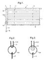
- Figure 1 shows a conventional pleated blind 1 with a cord lock 3 as a longitudinal extension on the left side of its longitudinally-extending head rail 5.
- a longitudinally-extending bottom rail 9 of the blind 1 can be raised and lowered to retract or to deploy a pleated blind fabric 7 by means of conventional lift cords 11, 13 (shown as a single line in Figure 1 ).
- Each lift cord 11, 13 is attached, at one end, to the bottom rail 9 and extends upwardly through the head rail 5 and then through the cord lock 3.
- the lift cords 11, 13 extend downwardly from the cord lock 3, are looped through a conventional cord connector 15 and then extend upwardly toward the cord lock.
- the free ends of the lift cords are then attached to a fixed cord end receptor 16 on the cord lock.
- the cord connector 15 can be pulled by means of a single manipulating cord 17, depending from the cord connector, or by means of a tassel 19, depending from the manipulating cord 17, to raise the bottom rail 9 by a distance that is twice the pulling stroke on the manipulating cord 17.
- This arrangement is particularly suitable for a large pleated blind 1 and prevents excessive lengths of lift cords 11, 13 dangling downwardly when the blind is raised. In this regard, excess lengths of lift cords can present a safety hazard for small children.
- Figure 2 shows an alternative cord connector 15A which can guide the looped lift cords 11, 13 of the blind 1 over a curved guiding surface 21.
- Figure 3 shows another alternative cord connector 15B which can guide the looped lift cords 11, 13 of the blind 1 over a rotatable guide pulley 23.
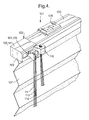
- Figures 4-7 shows a first embodiment of a cord lock 103 of the invention which is similar to the cord lock 3 of Figure 1 and for which corresponding reference numerals (greater by 100) are used below for describing the same parts or corresponding parts.
- Figure 4 shows a pleated blind 101 with its cord lock 103 attached to the left end of its head rail 105.
- the head rail 105 can be mounted on an overhead structure by means of conventional mounting brackets 106.
- the head rail 105 also holds an upper edge of a pleated blind fabric 107 which may be retracted by pulling lift cords 111, 113 and 114 together through the cord lock 103.
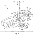
- the cord lock 103 has a housing 133, best seen in Figure 5 .
- a right part of the housing 133 can be inserted in the left end of the head rail 105 as seen from Figures 4 , 6 and 7 .
- Figure 4 also shows the lift cords 111 etc. exiting the cord lock 103 through a cord-guiding funnel 125 on the front of a generally laterally-extending cord-guiding passage 126 in a front portion 122 of a movable, generally laterally-extending locking lever 127 in the housing 133 of the cord lock.
- the funnnel 125 and a front portion of the cord-guiding passage 126 extend outwardly from the front of the housing 133.
- the lift cords pass downwardly from the funnel 125 and through a connector (not shown) and are then attached to a fixed cord end receptor 116 on the front of a laterally-extending front wall 118 of the cord lock housing 133, located on its front at about its longitudinal middle.
- the housing's front wall 118 has a left-facing laterally-extending shoulder 120, against which the right side 122A of the front portion 122 of the locking lever 127 can abut to limit its rightward movement during counter-clockwise pivoting of the locking lever as shown in Figure 6 .
- Figure 5 best shows the cord lock's housing 133 and locking lever 127, including its funnel 125 at the front of its cord-guiding passage 126.
- the right side of the housing 133 has a longitudinally-(rightwardly-)extending profiled tongue 137 which is adapted to be inserted into, and snugly fit within, the contours of the left side of the head rail 105.
- the profiled tongue 137 has a longitudinally-extending channel 139, through which the lift cords 111 etc. can extend longitudinally from the cord lock housing 133 into the head rail 105.
- the housing 133 also includes a cover 141, and the cord end receptor 116 of the housing includes a recessed cavity 143 for holding a knot at the end of each lift cord.
- the locking lever 127 extends horizontally- and rearwardly into the cord lock housing 133 and is pivotally connected to a vertically-extending cylindrical pivot pin 129.
- the cord-guiding passage 126 in the front portion 122 of the locking lever 127 extends laterally (rearwardly) from the funnel 125 toward the pivot pin 129.
- a rear portion 124 of the locking lever 127, rearwardly of the pivot pin, has a vertically- and longitudinally-extending rear surface with a cord-gripping formation 145.
- the cord-gripping formation 145 preferably includes a rearwardly-and rightwardly-facing abutment 146 with a cord-gripping surface
- a vertically- and longitudinally-extending front surface on the rear wall 147 of the cord lock housing 133 includes a locking surface 161.
- the locking surface 161 is located longitudinally closer to the housing's channel 139 than is the cord-gripping formation 145 in the rear surface of the locking lever 127.
- the locking surface 161 is preferably also a shoulder on the front surface of the rear wall 147 with a frontally-and leftwardly-facing cord-gripping surface. Thereby, the shoulder of the locking surface 161 can abut against the cord-gripping formation 145 of the locking lever in order to limit its clockwise (rightward) movement as shown in Figure 7 .
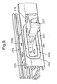
- each pull cord (only 111 is shown) extends upwardly and then rearwardly and horizontally into the cord lock housing 133. Then, as shown in Figures 6 and 7 , each pull cord extends horizontally within the housing: rearwardly through the funnel 125 and cord-guiding passage 126 of the locking lever 127, rearwardly and to the left about a vertically-extending cylindrical cord-guiding pin 149, rearwardly and to the right between the cord-gripping formation 145 and the rear wall 147 and then rearwardly and to the right towards the channel 139 and the head rail 105.
- the cord-gripping formation 145 preferably is adapted to significantly restrain longitudinal movement of the lift cords 111 etc. along its cord-gripping surface, particularly movement to the right, towards the channel 139, when the cord-gripping formation is moved clockwise (to the right) to actually engage the locking surface 161 (as in Figure 7 ).
- the cord-gripping formation 145 also is preferably adapted not to significantly restrain longitudinal movement of the lift cords along its cord-gripping surface when it is not actually engaging the locking surface 161 (as in Figure 6 ).
- the locking surface 161 preferably is adapted to significantly restrain longitudinal movement of the lift cords 111 etc. along it only when the cord-gripping formation 145 is moved to the right to actually engage it (as in Figure 7 ).
- the pivot pin 129 is received in a first pair of holes 135A, 135B (not shown in Figure 5 ), respectively in a horizontally-extending top wall 155 and a horizontally-extending bottom wall 157 of the housing 133.
- the pivot pin 129 is located longitudinally between the cord-guiding pin 149 and the locking surface 161 on the rear wall 147 of the housing 133 and laterally between the front and rear portions 122, 124 of the locking lever.
- the locking lever 127 has a vertically-extending bore 131 that is located laterally between its cord-gripping formation 145 and its cord-guiding passage 126 and is pivotally positioned on the pivot pin 129.
- the locking lever 127 can pivot horizontally about the pivot pin 129, between the top and bottom walls 155, 157 of the housing, so that the rear portion 124 of the locking lever and its cord-gripping formation 145 move rearwardly and horizontally to the right (i.e., clockwise), towards the locking surface 161, when its front portion 122 and its cord-guiding passage 126 are moved horizontally to the left, away from the locking surface 161.
- the cord-gripping formation 145 of the locking lever 127 can tightly hold the pull cords 111 etc. against the locking surface 161 on the rear wall 147 of the housing 137 when the cord-gripping formation is urged rightwardly against the locking surface 161.
- the cord-guiding pin 149 in the housing 133 guides each lift cord 111 etc. at an appropriate angle between the cord-gripping formation 145 at the rear of the locking lever 127 and the rear wall 147 of the housing, so that the lift cords frictionally contact, and move longitudinally along, the cord-gripping formation 145 and move longitudinally along the channel 139 whenever the lift cords 111 etc. are being pulled from, or released towards, the cord lock 103 and the head rail 105 by a user of the blind 101.
- the cord-guiding pin 149 is mounted, in the housing, on the opposite longitudinal side of the locking lever 127 from the channel 139, laterally between the front and rear of the locking lever, and either rearwardly or frontwardly of the pivot pin 129.
- the cord-guiding pin 149 can be mounted in either a second pair of vertically-aligned holes 151A and 151B, rearwardly of the pivot pin 129, or a third pair of vertically-aligned holes 153A and 153B, frontwardly of the pivot pin, in the top and bottom walls 155 and 157, respectively, of the housing.
- the location of the cord-guiding pin 149 will be selected depending upon which is better, in view of whether the cord lock is to be used with a head rail that is horizontal or is slanted.
- the cord-guiding pin 149 is preferably located (in Figure 6 ) in the third pair of holes 153A and 153B, laterally farther from the rear wall 147, for a vertically-slanted head rail 105 and is preferably located (in Figure 7 ) in the second pair of holes 151A and 151B, laterally closer to the rear wall 147, for a horizontal head rail 105.
- the locking lever 127 has been pivoted in a counter-clockwise direction, so that its rear is moved longitudinally (to the left) away from the channel 139, by a user of the blind 101 pulling on the lift cords 111 etc.
- the cord-gripping formation 145 on the rear portion 124 of the locking lever has been moved longitudinally away from the locking surface 161 on the rear wall 147 of the housing 133 and preferably also frontwardly away from the locking surface 161.
- This has disengaged the cord-gripping formation 145 from the locking surface 161.
- the lift cords can move relatively freely longitudinally between the rear portion 124 of the locking lever and the rear wall 147 of the housing.
- the weight of the covering 107 on the lift cords 111 etc. causes the lift cords to continuously engage frictionally the rear portion 124 of the locking lever and its cord-gripping formation 145 and to continuously urge the rear portion of the locking lever to pivot back in a clockwise direction, longitudinally to the right toward the channel 139, from its counter-clockwise position in Figure 6 , caused by the user's pull on the lift cords. Nevertheless while the user continues to pull on the lift cords, the rear of the locking lever remains pivoted to the left, in a counter-clockwise position, and the cord lock remains unlocked.
- the cord-gripping formation 145 on the rear portion 124 of the locking lever 127 is urged against, and engages, the cord-gripping surface of the locking surface 161 of the rear wall 147 of the housing 133.
- the cord-gripping formation 145 and the locking surface 161 grip tightly the lift cords 111, etc. between them and prevent the lift cords from moving longitudinally between them.
- the cord lock 103 automatically moves from its unlocked position in Figure 6 to its locked position in Figure 7 . This occurs when the user of the blind 101 releases the lift cords 111 etc., which allows the weight of the pleated blind fabric 107 to pull the lift cords upwardly to the funnel 125 on the front of the locking lever, then rearwardly through its cord-guiding passage 126, then around the cord-guiding pin 149 and then longitudinally (to the right) between the rear wall 147 of the housing 133 and the rear of the locking lever 127, about and along its cord-gripping formation 145, toward the channel 139 as shown in Figure 6 .
- the user can then easily pull further on the lift cords to pull up the pleated blind fabric 107 and pull the lift cords longitudinally to the left within the channel 139 and then about and along the cord-gripping formation 145, then around the cord-guiding pin 149, then through the cord-guiding passage 126, and then downwardly from the funnel 125 as shown in Figure 6 .
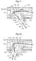
- Figures 8-14 show a second embodiment of a cord lock 203 of the invention which is similar to the cord lock 103 of Figures 4-7 and for which corresponding reference numerals (greater by 100) are used below for describing the same parts or corresponding parts.
- the cord lock 203 for one or more lift cords 211 etc. is accommodated in an opening 263 in the front of the head rail 205 of a pleated blind 201.
- the cord lock 203 has a horizontally- and rearwardly-extending locking lever 227.
- a front portion 222 of the locking lever 227 contains a generally laterally-extending rear surface cord-guiding passage 226, and a rear portion 224 of the locking lever 227 has a vertically- and longitudinally-extending rear surface with a cord-gripping formation 245.
- the cord lock 203 also has a vertically- and frontally-extending locking surface 261 on the rear wall 247 of the housing 233.
- a cord end receptor 216 is also provided in a front portion 222 of the locking lever 227 when the blind 201 includes a cord connector like those shown in Figure 2 or 3 .
- the locking lever 227 has a bore 231, pivotally located on a pivot pin 229.
- the pivot pin 229 is mounted in a first pair of holes 235A and 235B in respectively the top wall 255 and bottom wall 257 of the housing 233.
- the locking lever 227 can pivot horizontally about the pivot pin, between the top and bottom walls 255, 257 of the housing 233, so that the rear portion 224 of the locking lever and its cord-gripping formation 245 automatically move rearwardly and horizontally to the right (clockwise), towards the locking surface 261, as shown in Figure 12 , when a user of the blind 201 releases its lift cords 211 etc.
- the cord lock 203 also has a vertically-extending cylindrical cord-guiding pin 249.
- the cord-guiding pin 249 can be mounted at two different horizontal locations in the housing 233, corresponding to either a second pair of vertically-aligned holes 251A and 251B (as shown in Figures 11 and 12 ) or a third pair of vertically-aligned holes 253A and 253B (as shown in Figures 13 and 14 ) in the top and bottom walls 255 and 257, respectively, of the housing.
- the cord lock housing 233 has an interior left-facing laterally-extending wall with a shoulder 220, against which the right side 222A of the front portion 222 of the locking lever 227 can abut to limit its rightward movement during counter-clockwise pivoting of the locking lever as shown in Figures 11 and 13 .
- the cord lock housing 233 features, on its longitudinally opposite sides, a pair of longitudinally-resilient tongues 271 and 273.
- the tongues 271 and 273 extend frontwardly and longitudinally away from middle portions of longitudinally opposite sides of the housing 233.
- the tongues are thereby adapted to frictionally engage internal portions of the head rail 205 on longitudinally opposite sides of the opening 263 in the front of the head rail and on longitudinally opposite sides of the housing, so as to retain the housing in the opening.
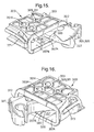
- Figures 15 and 16 show a third embodiment of a cord lock 303 of the invention which is similar to the cord lock 103 of Figures 8-14 and for which corresponding reference numerals (greater by 200) are used below for describing the same parts or corresponding parts.
- the cord lock 303 has a horizontally- and rearwardly-extending locking lever 327.
- a front portion 322 of the locking lever 327 contains a generally laterally-extending cord-guiding passage 326, and a rear portion (not shown) of the locking lever 327 has a vertically- and rearwardly-extending surface with a cord-gripping formation (not shown).
- the cord lock 303 also has a vertically- and frontally-extending locking surface (not shown) on the rear wall (not shown) of its housing 333.
- the cord lock housing 333 features a stepped horizontally-extending lower wall 357.
- a vertically-extending threshold 340 divides the lower wall 357 into a right lower section 357A, adjacent the locking surface (not shown), and a left upper section 357B, adjacent a cord-guiding pin (not shown) between the locking lever's cord-guiding passage 326 and cord-gripping formation (not shown).
- parts of the front portion 322 of the locking lever 327 rest on the lower section 357A of the lower wall 357.
- FIGs 17-19 show a fourth embodiment of a cord lock 403 of the invention which is similar to the cord lock 103 of Figures 8-14 and for which corresponding reference numerals (greater by 300) are used below for describing the same parts or corresponding parts.
- the cord lock 403 has a horizontally- and rearwardly-extending locking lever 427.
- a front portion 422 of the locking lever 427 contains a generally laterally-extending cord-guiding passage 426, and a separate rear portion 424 of the locking lever 427 has a vertically- and rearwardly-extending surface with a cord-gripping formation 445.
- a front part 424B of the rear portion 424 and an adjacent rear part 422B of the front portion 422 are pivotally connected to the pivot pin 429. At least the front part 424B of the rear portion 424 lies atop the rear part 422B of the front portion 422.
- the cord lock 403 also has a vertically- and frontally-extending locking surface 461 on the rear wall 447 of its housing 433.
- the front and rear portions 422, 424 of the locking lever 427 can swivel counter-clockwise about the pivot pin 429 when a user of a blind with the cord lock 403 pulls lift cords (not shown), extending through the cord lock 403.
- the rear portion 424 can swivel counter-clockwise further, preferably by about 15°, than the front portion 422 with longitudinal movement of the lift cords toward the cord-guiding pin 449.
- the limit to the counter-clockwise swivel of the rear portion 424, relative to the front portion 422, is established by the abutment of a vertically-extending left front edge 470 of the rear portion 424 with an adjacent vertically-extending left rear edge 472 of the front portion 422.
- the housing 433 has a left-facing laterally-extending interior wall with a shoulder 420, against which the right side 422A of the front portion 422 of the locking lever 427 can abut to limit its rightward movement during counter-clockwise pivoting of the locking lever as shown in Figure 19 .
- the front and rear portions 422, 424 of the locking lever 427 can also swivel clockwise about the pivot pin 429 when the user releases the lift cords (not shown).
- the rear portion 424 can swivel clockwise further than the front portion 422 with longitudinal movement of the lift cords away from the cord-guiding pin 449.
- the limit to the clockwise swivel of the rear portion 424, relative to the front portion 422, is established by the abutment of a vertically-extending right rear edge 474 of the rear portion with an adjacent vertically-extending right front edge 476 of the front portion.
- the cord-gripping formation 445 on the rear portion 424 of the locking lever can engage the locking surface 461 on the rear wall 447 of the housing to hold the lift cords when the user releases his grip on them.
Landscapes
- Engineering & Computer Science (AREA)
- Structural Engineering (AREA)
- Architecture (AREA)
- Civil Engineering (AREA)
- Blinds (AREA)
Claims (14)
- Schnurklemme (103, 203, 303, 403), speziell für eine Fensterabdeckung, insbesondere eine Faltjalousie (101, 201, 201, 401), umfassend- ein Gehäuse (133, 233, 333, 433), das in eine in Längsrichtung verlaufende Kopfschiene (105, 205, 305, 405) einer Fensterabdeckung eingesetzt werden kann und parallele erste und zweite Wände (155, 255, 355, 455, 157, 257, 357, 457) und eine Rückwand (147, 247, 347, 447) hat;- einen Drehzapfen (129, 229, 329, 429), der sich zwischen der ersten und der zweiten Wand des Gehäuses erstreckt;- einen Arretierhebel (127, 227, 327, 427) innerhalb des Gehäuses, der mit einem Ende in der Nähe der Rückwand (147, 247, 347, 447) angeordnet ist und an einem entgegengesetzten Ende einen Schnurführungsdurchlass (126, 226, 326, 426) hat, wobei der Arretierhebel um besagten Drehzapfen (129, 229, 329, 429) schwenkbar ist, dadurch gekennzeichnet, dassdie Rückwand (147, 247, 347, 447) eine Arretierfläche (161, 261, 361,461) hat, die sich zwischen der ersten und der zweiten Wand erstreckt;
der Arretierhebel (127, 227, 327, 427) mit einem Ende in der Nähe der Arretierfläche (161, 261, 361,461) angeordnet ist und das entgegengesetzte Ende von der Arretierfläche (161, 261, 361, 461) entfernt angeordnet ist;
der Arretierhebel (127, 227, 327, 427) eine schnurgreifendes Gebilde (145, 245, 345, 445) an besagtem einen Ende aufweist und der besagte Drehzapfen (129, 229, 329, 429) zwischen dem schnurgreifenden Gebilde (145, 245, 345, 445) und dem Schnurführungsdurchlass (126, 226, 326, 426) angeordnet ist, so dass sich das schnurgreifende Gebilde mit der Schwenkbewegung des Arretierhebels um den Drehzapfen in den Eingriff und aus dem Eingriff mit der Arretierfläche bewegen kann und Zugschnüre, die sich zwischen dem Arretierhebel (127, 227, 327, 427) und der Rückwand (147, 247, 347, 447) erstrecken, fest halten kann, wenn das schnurgreifende Gebilde (145, 245, 345, 445) zur Arretierfläche (161, 261, 361, 461) gedrückt wird, und dass die Schnurklemme weiter umfasst:- eine feststehende Führungsfläche (149, 249, 349, 449), die lateral in Bezug auf die besagte Rückwand (147, 247, 347, 447) entweder hinter oder vor dem Drehzapfen (129, 229, 329, 429) und zwischen der Vorderseite und der Rückseite des Arretierhebels (127, 227, 327, 427) angeordnet ist, so dass sich Zugschnüre entlang des schnurgreifenden Gebildes (145, 245, 345, 445), um die feststehende Führungsfläche (149, 249, 349, 449) und durch den Schnurführungsdurchlass (126, 226, 326, 426) erstrecken können. - Schnurklemme (103, 203, 303, 403) gemäß Anspruch 1, bei der die erste und die zweite Wand (155, 255, 355, 455, 157, 257, 357, 457) und der Arretierhebel (127, 227, 327, 427) sich horizontal erstrecken, der Schnurführungsdurchlass (126, 226, 326, 426) sich lateral erstreckt und der Drehzapfen (129, 229, 329, 429) und die feststehende Führungsfläche (149, 249, 349, 449) sich vertikal erstrecken.
- Schnurklemme (103, 203, 303, 403) gemäß Anspruch 2, bei der der Drehzapfen (129, 229, 329, 429) lateral zwischen der feststehenden Führungsfläche (149, 249, 349, 449) und der Arretierfläche (161, 261, 361, 461) angeordnet ist.
- Schnurklemme (103, 203, 303, 403) gemäß Anspruch 3, bei der der Drehzapfen (129, 229, 329, 429) in Längsrichtung zwischen der feststehenden Führungsfläche (149, 249, 349, 449) und der Arretierfläche (161, 261, 361, 461) angeordnet ist.
- Schnurklemme (103, 203, 303, 403) gemäß Anspruch 3 oder 4, die so angeordnet ist, dass sie einen oberen Abschnitt einer Hubschnur (111, 113, 114) einer Fensterabdeckung so aufnimmt, dass dieser sich verschieblich nach oben zum Schnurführungsdurchlass (126, 226, 326, 426) und dann horizontal und lateral durch den Schnurführungsdurchlass (126, 226, 326, 426), dann horizontal und lateral über die feststehende Führungsfläche (149, 249, 349, 449), dann horizontal und in Längsrichtung um das schnurgreifende Gebilde (145, 245, 345, 445) und dann horizontal und in Längsrichtung zwischen dem schnurgreifenden Gebilde und der Arretierfläche (161, 261, 361, 461) erstreckt.
- Schnurklemme (103, 203, 303, 403) gemäß einem der Ansprüche 1 bis 5, bei der die feststehende Führungsfläche (149, 249, 349, 449) sich ebenfalls zwischen der ersten und der zweiten Wand (155, 255, 355, 455, 157, 257, 357, 457) des Gehäuse erstreckt.
- Schnurklemme (303) gemäß einem der Ansprüche 1 bis 5, bei der eine untere erste Wand (357) einen unteren Abschnitt (357A) auf einer Längsseite in der Nähe der Arretierfläche und einen oberen Abschnitt (357B) auf einer gegenüberliegenden Längsseite in der Nähe der Schnurführungsfläche aufweist.
- Schnurklemme (303) nach Anspruch 7, bei der eine vertikal verlaufende Schwelle (240) zwischen dem unteren Abschnitt (357A) und dem oberen Abschnitt (357B) der unteren ersten Wand (357) vorgesehen ist.
- Schnurklemme (403) gemäß einem der Ansprüche 1 bis 8, bei der der Arretierhebel (427) einen ersten Abschnitt (422) aufweist, in dem der Schnurführungsdurchlass (426) angeordnet ist, und einen zweiten Abschnitt (424) aufweist, auf dem das schnurgreifende Gebilde (445) angeordnet ist, wobei benachbarte erste und zweite Teile (422B, 424B) der ersten und zweiten Abschnitte (422, 424) schwenkbar mit dem Drehzapfen (429) verbunden sind und wobei bei einer Schwenkbewegung des Arretierhebels um den Drehzapfen der zweite Abschnitt (424) weiter, vorzugsweise um etwa 15° weiter, um den Drehzapfen (429) schwenken kann als der erste Abschnitt (422).
- Schnurklemme (403) gemäß Anspruch 9, bei der mindestens der zweite Teil (424B) des zweiten Abschnitts (424) oberhalb des ersten Teils (422B) des ersten Abschnitts (422) liegt.
- Schnurklemme (403) gemäß Anspruch 9 oder 10, bei der das Schwenken des zweiten Abschnitts (424) im Verhältnis zum ersten Abschnitt (422) um den Drehzapfen (429) beschränkt ist durch das Gegeneinanderstoßen ihrer benachbarten einander gegenüberliegenden Kanten (470, 472, 474, 476).
- Schnurklemme gemäß Anspruch 1, bei der im Gebrauch eine Hubschnur verschieblich durch ein Zugelement angeordnet ist und mit ihrem freien Ende in Bezug auf das Gehäuse (133, 233, 333, 433) ortsfest verbunden ist.
- Schnurklemme gemäß Anspruch 1, bei der die feststehende Führungsfläche (149, 249, 349, 449) Teil eines Stifts ist, der wahlweise in einer von mindestens zwei verschiedenen vorgegebenen Positionen angebracht werden kann.
- Schnurklemme gemäß Anspruch 1 oder 13, bei der die feststehende Führungsfläche (149, 249, 349, 449) auf einen Element vorgesehen ist, das wahlweise in mindestens zwei verschiedenen Positionen im Gehäuse angebracht werden kann.
Priority Applications (1)
| Application Number | Priority Date | Filing Date | Title |
|---|---|---|---|
| EP20040255070 EP1512828B1 (de) | 2003-09-02 | 2004-08-23 | Automatische Schnurklemme |
Applications Claiming Priority (5)
| Application Number | Priority Date | Filing Date | Title |
|---|---|---|---|
| EP03077752 | 2003-09-02 | ||
| EP03077752 | 2003-09-02 | ||
| EP04076988 | 2004-07-09 | ||
| EP04076988 | 2004-07-09 | ||
| EP20040255070 EP1512828B1 (de) | 2003-09-02 | 2004-08-23 | Automatische Schnurklemme |
Publications (2)
| Publication Number | Publication Date |
|---|---|
| EP1512828A1 EP1512828A1 (de) | 2005-03-09 |
| EP1512828B1 true EP1512828B1 (de) | 2010-08-18 |
Family
ID=34139268
Family Applications (1)
| Application Number | Title | Priority Date | Filing Date |
|---|---|---|---|
| EP20040255070 Expired - Lifetime EP1512828B1 (de) | 2003-09-02 | 2004-08-23 | Automatische Schnurklemme |
Country Status (1)
| Country | Link |
|---|---|
| EP (1) | EP1512828B1 (de) |
Family Cites Families (7)
| Publication number | Priority date | Publication date | Assignee | Title |
|---|---|---|---|---|
| US2010286A (en) | 1935-04-23 | 1935-08-06 | Ry Lock Company Ltd | Venetian blind locking mechanism |
| DE1207826B (de) * | 1958-03-14 | 1965-12-23 | Vista G M B H | Selbsttaetige Klemmvorrichtung fuer eine Zugschnur von Lamellen-Jalousien od. dgl. |
| CH388125A (de) * | 1959-09-01 | 1965-02-15 | Vista Gmbh | Feststellvorrichtung für Zugorgane, beispielsweise Schnüre, Bänder, Gurte u. dgl. von Jalousien, Rolladen, Vorhängen u. dgl. |
| NL253400A (de) * | 1960-07-04 | |||
| NL8301108A (nl) * | 1982-08-31 | 1984-03-16 | Schoen Siegfried Joachim | Vergrendelinrichting en verbeterd trekorgaan voor trekkoorden van een op en neer beweegbaar scherm. |
| DE3242161A1 (de) | 1982-11-13 | 1984-05-17 | Hans 8100 Garmisch-Partenkirchen Langmatz | Wartungsfreier kunststoffmast fuer leuchten, verkehrsampeln, verkehrsschilder und dgl. |
| NL9401081A (nl) * | 1994-06-28 | 1996-02-01 | Verosol Nederland Bv | Koordrem. |
-
2004
- 2004-08-23 EP EP20040255070 patent/EP1512828B1/de not_active Expired - Lifetime
Also Published As
| Publication number | Publication date |
|---|---|
| EP1512828A1 (de) | 2005-03-09 |
Similar Documents
| Publication | Publication Date | Title |
|---|---|---|
| AU2004203612B2 (en) | A cord lock | |
| US6571854B1 (en) | Method and apparatus for fixing the length of a pull cord | |
| EP0941176B1 (de) | Abdeckrollo mit vereinfachter bedienung | |
| CA2470497C (en) | Brake for a cordless blind | |
| EP2063064B1 (de) | Sicherheitsvorrichtung zum Abdecken von Fenstern | |
| US7261138B2 (en) | Child safe cord lock | |
| KR101573426B1 (ko) | 건축물 개구부용 커버링들 상의 헤드레일들을 위한 록 레버 장착 브래킷 | |
| US8132610B2 (en) | Window covering | |
| US4807683A (en) | Retractable screen | |
| CA2178181C (en) | A connector for connecting pull cords | |
| CA2409966C (en) | Venetian blind that keeps lift cords concealed | |
| EP0382364A1 (de) | Bremsvorrichtung einer Jalousie | |
| EP0305081B1 (de) | Einziehbare Fensterabdeckvorrichtung | |
| EP1512828A1 (de) | Automatische Schnurklemme | |
| CA2404761A1 (en) | Venetian blind having lift cords kept from sight | |
| CN1625639A (zh) | 卷式窗帘的可释放绳索装置和断开端部 | |
| CA2327956C (en) | Releasable end stop | |
| CA2814575C (en) | Blind assembly | |
| EP1111184B1 (de) | Lösbarer Endanschlag | |
| KR101195828B1 (ko) | 블라인드용 권취장치 | |
| JP3906466B2 (ja) | シャッター | |
| EP0860577B1 (de) | Abdeckung für eine architektonische Öffnung | |
| EP2565362A1 (de) | Schlingenschnurspannungsvorrichtung für Fensterabdeckungen | |
| CN213501985U (zh) | 轮椅固定器 | |
| EP1514992B1 (de) | Sicherheitsschnurkupplung |
Legal Events
| Date | Code | Title | Description |
|---|---|---|---|
| PUAI | Public reference made under article 153(3) epc to a published international application that has entered the european phase |
Free format text: ORIGINAL CODE: 0009012 |
|
| AK | Designated contracting states |
Kind code of ref document: A1 Designated state(s): AT BE BG CH CY CZ DE DK EE ES FI FR GB GR HU IE IT LI LU MC NL PL PT RO SE SI SK TR |
|
| AX | Request for extension of the european patent |
Extension state: AL HR LT LV MK |
|
| 17P | Request for examination filed |
Effective date: 20050714 |
|
| AKX | Designation fees paid |
Designated state(s): AT BE BG CH CY CZ DE DK EE ES FI FR GB GR HU IE IT LI LU MC NL PL PT RO SE SI SK TR |
|
| 17Q | First examination report despatched |
Effective date: 20091113 |
|
| GRAP | Despatch of communication of intention to grant a patent |
Free format text: ORIGINAL CODE: EPIDOSNIGR1 |
|
| GRAS | Grant fee paid |
Free format text: ORIGINAL CODE: EPIDOSNIGR3 |
|
| RBV | Designated contracting states (corrected) |
Designated state(s): DE ES FR GB IT NL |
|
| GRAA | (expected) grant |
Free format text: ORIGINAL CODE: 0009210 |
|
| AK | Designated contracting states |
Kind code of ref document: B1 Designated state(s): DE ES FR GB IT NL |
|
| REG | Reference to a national code |
Ref country code: GB Ref legal event code: FG4D |
|
| REF | Corresponds to: |
Ref document number: 602004028695 Country of ref document: DE Date of ref document: 20100930 Kind code of ref document: P |
|
| REG | Reference to a national code |
Ref country code: DE Ref legal event code: R096 Ref document number: 602004028695 Country of ref document: DE Effective date: 20100930 |
|
| REG | Reference to a national code |
Ref country code: NL Ref legal event code: T3 Ref country code: ES Ref legal event code: FG2A Effective date: 20101124 |
|
| PLBE | No opposition filed within time limit |
Free format text: ORIGINAL CODE: 0009261 |
|
| STAA | Information on the status of an ep patent application or granted ep patent |
Free format text: STATUS: NO OPPOSITION FILED WITHIN TIME LIMIT |
|
| 26N | No opposition filed |
Effective date: 20110519 |
|
| REG | Reference to a national code |
Ref country code: DE Ref legal event code: R097 Ref document number: 602004028695 Country of ref document: DE Effective date: 20110519 |
|
| REG | Reference to a national code |
Ref country code: FR Ref legal event code: PLFP Year of fee payment: 12 |
|
| REG | Reference to a national code |
Ref country code: FR Ref legal event code: PLFP Year of fee payment: 13 |
|
| REG | Reference to a national code |
Ref country code: FR Ref legal event code: PLFP Year of fee payment: 14 |
|
| REG | Reference to a national code |
Ref country code: FR Ref legal event code: PLFP Year of fee payment: 15 |
|
| P01 | Opt-out of the competence of the unified patent court (upc) registered |
Effective date: 20230331 |
|
| PGFP | Annual fee paid to national office [announced via postgrant information from national office to epo] |
Ref country code: NL Payment date: 20230719 Year of fee payment: 20 |
|
| PGFP | Annual fee paid to national office [announced via postgrant information from national office to epo] |
Ref country code: IT Payment date: 20230711 Year of fee payment: 20 Ref country code: GB Payment date: 20230629 Year of fee payment: 20 Ref country code: ES Payment date: 20230908 Year of fee payment: 20 |
|
| PGFP | Annual fee paid to national office [announced via postgrant information from national office to epo] |
Ref country code: FR Payment date: 20230703 Year of fee payment: 20 Ref country code: DE Payment date: 20230703 Year of fee payment: 20 |
|
| REG | Reference to a national code |
Ref country code: DE Ref legal event code: R071 Ref document number: 602004028695 Country of ref document: DE |
|
| REG | Reference to a national code |
Ref country code: NL Ref legal event code: MK Effective date: 20240822 |
|
| REG | Reference to a national code |
Ref country code: ES Ref legal event code: FD2A Effective date: 20240830 |
|
| REG | Reference to a national code |
Ref country code: GB Ref legal event code: PE20 Expiry date: 20240822 |
|
| PG25 | Lapsed in a contracting state [announced via postgrant information from national office to epo] |
Ref country code: GB Free format text: LAPSE BECAUSE OF EXPIRATION OF PROTECTION Effective date: 20240822 |
|
| PG25 | Lapsed in a contracting state [announced via postgrant information from national office to epo] |
Ref country code: ES Free format text: LAPSE BECAUSE OF EXPIRATION OF PROTECTION Effective date: 20240824 |
|
| PG25 | Lapsed in a contracting state [announced via postgrant information from national office to epo] |
Ref country code: GB Free format text: LAPSE BECAUSE OF EXPIRATION OF PROTECTION Effective date: 20240822 Ref country code: ES Free format text: LAPSE BECAUSE OF EXPIRATION OF PROTECTION Effective date: 20240824 |