EP1512827A2 - Halter - Google Patents
Halter Download PDFInfo
- Publication number
- EP1512827A2 EP1512827A2 EP04255301A EP04255301A EP1512827A2 EP 1512827 A2 EP1512827 A2 EP 1512827A2 EP 04255301 A EP04255301 A EP 04255301A EP 04255301 A EP04255301 A EP 04255301A EP 1512827 A2 EP1512827 A2 EP 1512827A2
- Authority
- EP
- European Patent Office
- Prior art keywords
- bracket
- head rail
- locking
- arm
- locking member
- Prior art date
- Legal status (The legal status is an assumption and is not a legal conclusion. Google has not performed a legal analysis and makes no representation as to the accuracy of the status listed.)
- Withdrawn
Links
- 239000002184 metal Substances 0.000 description 1
Images

Classifications
-
- E—FIXED CONSTRUCTIONS
- E06—DOORS, WINDOWS, SHUTTERS, OR ROLLER BLINDS IN GENERAL; LADDERS
- E06B—FIXED OR MOVABLE CLOSURES FOR OPENINGS IN BUILDINGS, VEHICLES, FENCES OR LIKE ENCLOSURES IN GENERAL, e.g. DOORS, WINDOWS, BLINDS, GATES
- E06B9/00—Screening or protective devices for wall or similar openings, with or without operating or securing mechanisms; Closures of similar construction
- E06B9/24—Screens or other constructions affording protection against light, especially against sunshine; Similar screens for privacy or appearance; Slat blinds
- E06B9/26—Lamellar or like blinds, e.g. venetian blinds
- E06B9/28—Lamellar or like blinds, e.g. venetian blinds with horizontal lamellae, e.g. non-liftable
- E06B9/30—Lamellar or like blinds, e.g. venetian blinds with horizontal lamellae, e.g. non-liftable liftable
- E06B9/32—Operating, guiding, or securing devices therefor
- E06B9/323—Structure or support of upper box
Definitions
- the invention relates to a bracket for mounting a head rail of a window covering to a surface, the bracket having a body with opposite downwardly extending rims that have inturned end portions and are adapted to engage the rail.
- brackets are generally known as spring clips and are well known for mounting blind rails. See EP 0,862,881 of applicant, and US 3,299,943, US 4,363,459, US 5,131,616, US 5,529,273, GB 2,267,526.
- the spring clip body bridges the top of the head rail and the inwardly turned end portions of the downwardly extending rims snap into the profiled grooves of the head rail. Biased under substantial pressure of the spring the rail is held against the bracket.
- One of the bracket body rims usually will include a tab to facilitate flexing of the spring clip for rimoval of the head rail.
- a drawback of the spring clip is that is cannot be used for a the generally U-shaped head rails for venetian blinds and the like.
- These head rails are elongated, generally U-shaped profiles, having a bottom wall, opposite front and rear walls and an open top.
- the spring clip cannot be used for these head rails because the force of the spring needed for a secure mounting of the head rail, pulls the opposite walls of the head rails slightly inward. Thus the mounting characteristics of the clip are not sufficiently secure to prevent the blind rail for disengaging from the head rail.
- a bracket for mounting a head rail of a window covering product to a fixation surface
- the head rail being a generally elongated U-shaped profile comprising a bottom wall, opposite front and rear walls and an open top
- the bracket comprising a generally rectangular body including opposite rims that extend generally downwardly and include inwardly turned end portions which are adapted to engage the rail at upper edges of the front and rear walls, wherein: at least the upper edge of the rear wall of the head rail includes an outer portion that is distanced from the rear wall over a first width
- the bracket body can be mounted to the head rail by flexing at least the rear wall of the head rail inward over a distance which is at least equal to the first width D1 and wherein the bracket further comprises a locking member being movable between a locked and an unlocked position such that when the locking member is in the locked position at least the rear wall of the head rail is being prevented from flexing inward over said distance thus preventing inadvertent dismounting the bracket from the
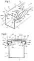
- Figures 1 and 2 show a first embodiment 1 of a mounting bracket holding a head rail 3.
- the head rail 3 is a conventional elongated generally U-shaped profile which includes a bottom wall 5, a front wall 7, a rear wall 9 and an open top 11.
- the front and rear walls 7,9 each include an upper edge 13, 15 that is suitably shaped to be engaged by thebracket 1.
- the head rail's front and rear upper edges 13, 15 each include a vertically-extending outer lower portion 13A, 15A, a vertically-extending outer middle portion 13B, 15B, an inwardly-extending, generally horizontal, upper portion 13C, 15C and a vertically-extending inner portion 13D, 15D.
- the inner portions 13D, 15D of the front and rear upper edges of the head rail are located within the front and rear walls 7, 9 and define a reduced width of the upper opening of the head rail compared to the width of the bottom wall 5.
- the inner portions 13D, 15D also extend generally parallel to the front and rear walls of the head rail.
- the bracket 1 also includes a generally rectangular body 17 shaped as a spring clip and a locking member 19.
- the spring clip body 17 can be formed from (e.g., punched out of) of a suitable spring metal sheet.
- the spring clip body 17 includes left and right, mounting apertures 21, 23 and front and rear rims 25, 27.
- the mounting apertures 21, 23 are for fixing the bracket to a fixation surface (not shown) such as a window sill or a wall with conventional fixation means such as screws or the like.
- the front and rear rims 25, 27 are generally downwardly-extending flanges and, as best seen in Figure 2, include inturned end portions 29, 31.
- the rear rim 27 further includes an outwardly turned tab 33, which can be flexed outwardly when the bracket is to be dismounted from the head rail 3.
- the locking member 19 of the mounting bracket 1 can rotate between a locked position and an unlocked position and includes an arm-like operating portion 35 and a locking portion 37.
- the arm 35 of the locking member 19 is rotatably mounted on the spring clip body 17 of the bracket 1 by a suitable rivet connection 39.
- the arm 35 extends over the upper front edge 13 of the head rail 3 and can thus be manupulated when the head rail is mounted to the bracket.
- the locking portion 37 includes a locking plate 41 including a pair locking flanges 43, 45 extending perpendicularly and generally vertically from the locking web.
- the locking plate 41 has a horizontal width between its locking flanges 43, 45 that is less than the width between the inner portions 13D, 15D of the upper edges 13, 15 of the front and rear walls 7, 9 of the head rail 3.
- the bracket 1 when mounted to the head rail 3 bridges its open top 11.
- the spring clip body 17 of the bracket can be easily mounted on the head rail by slightly flexing the front and rear walls 7, 9 of the head rail towards each other and snapping the spring clip body into engagement with the upper front and rear edges 13, 15 of the head rail.
- the front and rear rims 25, 27 of the spring clip body 17 engage the upper front and rear edges 13, 15 of the front and rear walls 7, 9 of the head rail 3.
- the inwardly-turned end portions 29, 31 of the spring clip body 17 engage the outer lower portions 13A, 15A of the upper front and rear edges 13, 15.
- Mounting and dismounting of the head rail 3 from the spring clip body 17 of the bracket 1 is effected by flexing inwardly the head rail's front and/or rear walls 7, 9 over a distance that is at least equal to the distance D1 between the rear wall 9 and the outer middle portion 15B of the rear upper edge 15 of the head rail. Inadvertent dismounting of the bracket can be prevented by rotating the locking member 19 to its locked position. When the locking member 19 is in the locked position as shown in Figures 1 and 2, its arm 35 is in a position adjacent to its left aperture 21.
- the locking flanges 43, 45 of the locking plate 41 are located inwardly of, and parallel to, the inner portions 13D, 15D of the upper edges 13, 15 of the front and rear walls of the head rail 3.
- the inner portions 13D, 15D of the upper edges 13,15 of the head rail 3 are enclosed between between the spring clip body 17 and its rims 25, 27 and the locking flanges 43, 45 of the locking plate 41.
- the front and rear walls 7, 9 of the head rail are thus prevented from flexing inwardly towards each other over a distance that is more than the distances D2, D3 between the front inner portion 13D and the front locking flange 43 and the rear inner portion 15D and the rear locking flange 45, respectively. These distance being smaller than is needed for dismounting thus prevent inadvertent dismounting of the head rail from the bracket.
- Figures 3 and 4 show a second embodiment 201 of a mounting bracket which is similar to the bracket 1 of Figures 1 and 2 and for which corresponding reference numerals (greater by 100) are used below for describing the same parts or corresponding parts.
- the bracket 101 holds a head rail 103 with a bottom wall 105, a front wall 107, a rear wall 109 and an open top 111.
- the front and rear walls each include an upper edge 113, 115 that is suitably shaped to be engaged by the bracket 101.
- the head rail rear upper edge 115 includes a vertically-extending outer lower portion 115A, a vertically-extending outer middle portion 115B, an inwardly-extending, generally horizontal, upper portion 115C and a vertically-extending inner portion 115D.
- the front upper edge 113 of the head rail 103 is differently shaped from that of the head rail 3 of Figurees 1 and 2.
- the head rail 103 is shaped as an open gutter rim 113 and its front upper edge extends completely inwardly from the front wall 107.
- the front upper edge 113 includes an inwardly and downwardly sloped portion 113C, a vertically-extending inner portion 113D and an upwardly- and outwardly-sloped upper portion 113A together creating an upwardly open gutter 113.
- the inner portions 113D, 115D of the front and rear upper edges 113, 115 of the head rail 103 are located inwardly of the front and rear walls 107, 109 and define a reduced width of the upper opening 111 of the head rail compared to the width of the bottom wall 105.
- the inner portions 113D, 115D also extend generally parallel to the front and rear walls 107, 109 of the head rail.
- the bracket 101 also includes a generally rectangular body 117 and a locking member 119.
- a generally C-shaped opening 117A in the bracket body 117 creates room for the locking member 119, which lowers the overall height of the bracket 101.
- the front rim 125 is divided into two sub rims 125A, 125B as best seen in Figure 3.
- the front and rear rims 125A, 125B,127 each include inturned end portions 129A, 129B, 131 for cooperating with the outwardly sloped portions 113A and 115A of the front and rear upper edges of the head rail.
- the rear rim 127 further includes an outwardly turned tab 133, which can be flexed outwardly when the bracket it to be dismounted from the head rail.
- the locking portion 137 of the locking member 119 includes a locking web 141 including a pair locking flanges 143, 145 extending perpendicular and generally vertically from the web.
- the locking web 141 has a horizontal width between the locking flanges 143, 145 that is less than the width between the vertically extending portions 113D and 115D of the front and rear upper edges 113, 115 of the front and rear walls of the head rail 103.
- the bracket 101 when mounted to the head rail 103 bridges the open top 111.
- the front and rear intumed rims 125A, 127 of the spring body 117 engage the outward turned portions 113A, 115A of the upper edges 113, 115 of the front and rear head rail walls 107, 109.
- the vertical locking flanges 143, 145 of the locking plate 141 are inward from and parallel to the edge portions 113B, 115D of the upper edges 113, 115 which are in turn parallel to the front and rear walls of the head rail 103.
- the arm 135 In the same locked position of the locking member 119, the arm 135 is in a position generally parallel to front wall upper rim 113. Also the arm 135 additionally includes a depending tang 135A which moves over the rim 113 and into the gutter 113D. The tang 135A prevents the arm from inadvertantly rotating away from front wall 107, and unlocking the bracket.
Landscapes
- Engineering & Computer Science (AREA)
- Structural Engineering (AREA)
- Architecture (AREA)
- Civil Engineering (AREA)
- Blinds (AREA)
- Window Of Vehicle (AREA)
- Curtains And Furnishings For Windows Or Doors (AREA)
Priority Applications (1)
| Application Number | Priority Date | Filing Date | Title |
|---|---|---|---|
| EP04255301A EP1512827A3 (de) | 2003-09-03 | 2004-09-01 | Halter |
Applications Claiming Priority (3)
| Application Number | Priority Date | Filing Date | Title |
|---|---|---|---|
| EP03077759 | 2003-09-03 | ||
| EP03077759 | 2003-09-03 | ||
| EP04255301A EP1512827A3 (de) | 2003-09-03 | 2004-09-01 | Halter |
Publications (2)
| Publication Number | Publication Date |
|---|---|
| EP1512827A2 true EP1512827A2 (de) | 2005-03-09 |
| EP1512827A3 EP1512827A3 (de) | 2007-04-11 |
Family
ID=34137583
Family Applications (1)
| Application Number | Title | Priority Date | Filing Date |
|---|---|---|---|
| EP04255301A Withdrawn EP1512827A3 (de) | 2003-09-03 | 2004-09-01 | Halter |
Country Status (1)
| Country | Link |
|---|---|
| EP (1) | EP1512827A3 (de) |
Cited By (1)
| Publication number | Priority date | Publication date | Assignee | Title |
|---|---|---|---|---|
| EP2500507A3 (de) * | 2011-03-18 | 2014-09-03 | Roma Kg | Kopfleistenhalter |
Citations (6)
| Publication number | Priority date | Publication date | Assignee | Title |
|---|---|---|---|---|
| US3299943A (en) | 1964-07-23 | 1967-01-24 | Ralph M Poe | Vertical louver blind apparatus |
| US4363459A (en) | 1980-12-05 | 1982-12-14 | Joanna Western Mills Company | Adjustable wall mounted bracket |
| US5131616A (en) | 1990-10-22 | 1992-07-21 | Graber Industries, Inc. | Bracket for adjustably supporting a headrail |
| GB2267526A (en) | 1992-05-09 | 1993-12-08 | Eclipse Blinds Ltd | Blind bracket with release mechanism |
| US5529273A (en) | 1994-08-19 | 1996-06-25 | Benthin; Siegfried | Mounting bracket |
| EP0862881A2 (de) | 1997-02-19 | 1998-09-09 | Hunter Douglas Industries B.V. | Befestigungssytem |
Family Cites Families (3)
| Publication number | Priority date | Publication date | Assignee | Title |
|---|---|---|---|---|
| US4254813A (en) * | 1979-06-20 | 1981-03-10 | Hunter Douglas International N.V. | Valance bracket for vertical venetian blind |
| DE3135790A1 (de) * | 1980-08-25 | 1983-03-24 | Berthold Haller GmbH & Co KG, 7209 Aldingen | Jalousie |
| US5042553A (en) * | 1990-03-14 | 1991-08-27 | Levolor Corporation | Window blind headrail and mounting bracket |
-
2004
- 2004-09-01 EP EP04255301A patent/EP1512827A3/de not_active Withdrawn
Patent Citations (6)
| Publication number | Priority date | Publication date | Assignee | Title |
|---|---|---|---|---|
| US3299943A (en) | 1964-07-23 | 1967-01-24 | Ralph M Poe | Vertical louver blind apparatus |
| US4363459A (en) | 1980-12-05 | 1982-12-14 | Joanna Western Mills Company | Adjustable wall mounted bracket |
| US5131616A (en) | 1990-10-22 | 1992-07-21 | Graber Industries, Inc. | Bracket for adjustably supporting a headrail |
| GB2267526A (en) | 1992-05-09 | 1993-12-08 | Eclipse Blinds Ltd | Blind bracket with release mechanism |
| US5529273A (en) | 1994-08-19 | 1996-06-25 | Benthin; Siegfried | Mounting bracket |
| EP0862881A2 (de) | 1997-02-19 | 1998-09-09 | Hunter Douglas Industries B.V. | Befestigungssytem |
Cited By (1)
| Publication number | Priority date | Publication date | Assignee | Title |
|---|---|---|---|---|
| EP2500507A3 (de) * | 2011-03-18 | 2014-09-03 | Roma Kg | Kopfleistenhalter |
Also Published As
| Publication number | Publication date |
|---|---|
| EP1512827A3 (de) | 2007-04-11 |
Similar Documents
| Publication | Publication Date | Title |
|---|---|---|
| US4411401A (en) | Headrail mounting bracket | |
| US11725834B2 (en) | Window frame for air conditioner unit and air conditioner unit for use therewith | |
| US6769214B1 (en) | Strip for retaining storm door window elements | |
| EP1297234B1 (de) | Schienengeführte tür mit aufgeklemmter vorrichtung, um die gleitrollen in den schienen zu halten | |
| US10584528B2 (en) | End cap for a rail for a window covering | |
| CA1303964C (en) | Valance bracket for a vertical blind | |
| US5127458A (en) | Venetian blind | |
| US6322029B1 (en) | Installation bracket | |
| US6382296B1 (en) | Headrail and bracket system for window coverings | |
| US20060021718A1 (en) | Mounting bracket | |
| US7516771B2 (en) | Lock lever mounting bracket for headrails on coverings for architectural openings | |
| US4399856A (en) | Adjustable valance suspension bracket | |
| US3992815A (en) | Window sash and frame | |
| EP1669537B1 (de) | Führungseinrichtung für aufrollbare Stores | |
| US6935078B1 (en) | Anchor fastener clip | |
| US7178300B2 (en) | Latch-type tile mounting system | |
| US4057937A (en) | Window sash assembly | |
| EP1512827A2 (de) | Halter | |
| CA1196568A (en) | Wall mount bracket for a venetian blind headrail | |
| US5265837A (en) | End support for window covering assembly | |
| US6823926B1 (en) | Cord lock | |
| GB2342154A (en) | Ventilitation device | |
| JP3930230B2 (ja) | 空気調和機の窓据付装置 | |
| EP1624149A2 (de) | Befestigungsträger | |
| US3228152A (en) | Awnings |
Legal Events
| Date | Code | Title | Description |
|---|---|---|---|
| PUAI | Public reference made under article 153(3) epc to a published international application that has entered the european phase |
Free format text: ORIGINAL CODE: 0009012 |
|
| AK | Designated contracting states |
Kind code of ref document: A2 Designated state(s): AT BE BG CH CY CZ DE DK EE ES FI FR GB GR HU IE IT LI LU MC NL PL PT RO SE SI SK TR |
|
| AX | Request for extension of the european patent |
Extension state: AL HR LT LV MK |
|
| PUAL | Search report despatched |
Free format text: ORIGINAL CODE: 0009013 |
|
| AK | Designated contracting states |
Kind code of ref document: A3 Designated state(s): AT BE BG CH CY CZ DE DK EE ES FI FR GB GR HU IE IT LI LU MC NL PL PT RO SE SI SK TR |
|
| AX | Request for extension of the european patent |
Extension state: AL HR LT LV MK |
|
| RIC1 | Information provided on ipc code assigned before grant |
Ipc: E06B 9/323 20060101ALI20070302BHEP Ipc: E06B 9/266 20060101AFI20041215BHEP |
|
| 17P | Request for examination filed |
Effective date: 20071004 |
|
| GRAP | Despatch of communication of intention to grant a patent |
Free format text: ORIGINAL CODE: EPIDOSNIGR1 |
|
| AKX | Designation fees paid |
Designated state(s): AT BE BG CH CY CZ DE DK EE ES FI FR GB GR HU IE IT LI LU MC NL PL PT RO SE SI SK TR |
|
| STAA | Information on the status of an ep patent application or granted ep patent |
Free format text: STATUS: THE APPLICATION IS DEEMED TO BE WITHDRAWN |
|
| 18D | Application deemed to be withdrawn |
Effective date: 20080411 |