EP1512822A1 - Schiebetürantrieb für die Schiebetür eines Kraftfahrzeuges - Google Patents
Schiebetürantrieb für die Schiebetür eines Kraftfahrzeuges Download PDFInfo
- Publication number
- EP1512822A1 EP1512822A1 EP04021260A EP04021260A EP1512822A1 EP 1512822 A1 EP1512822 A1 EP 1512822A1 EP 04021260 A EP04021260 A EP 04021260A EP 04021260 A EP04021260 A EP 04021260A EP 1512822 A1 EP1512822 A1 EP 1512822A1
- Authority
- EP
- European Patent Office
- Prior art keywords
- sliding door
- drive
- carriage
- gear
- drive unit
- Prior art date
- Legal status (The legal status is an assumption and is not a legal conclusion. Google has not performed a legal analysis and makes no representation as to the accuracy of the status listed.)
- Granted
Links
Images


Classifications
-
- E—FIXED CONSTRUCTIONS
- E05—LOCKS; KEYS; WINDOW OR DOOR FITTINGS; SAFES
- E05D—HINGES OR SUSPENSION DEVICES FOR DOORS, WINDOWS OR WINGS
- E05D15/00—Suspension arrangements for wings
- E05D15/06—Suspension arrangements for wings for wings sliding horizontally more or less in their own plane
- E05D15/10—Suspension arrangements for wings for wings sliding horizontally more or less in their own plane movable out of one plane into a second parallel plane
- E05D15/1042—Suspension arrangements for wings for wings sliding horizontally more or less in their own plane movable out of one plane into a second parallel plane with transversely moving carriage
- E05D15/1047—Suspension arrangements for wings for wings sliding horizontally more or less in their own plane movable out of one plane into a second parallel plane with transversely moving carriage specially adapted for vehicles
-
- E—FIXED CONSTRUCTIONS
- E05—LOCKS; KEYS; WINDOW OR DOOR FITTINGS; SAFES
- E05F—DEVICES FOR MOVING WINGS INTO OPEN OR CLOSED POSITION; CHECKS FOR WINGS; WING FITTINGS NOT OTHERWISE PROVIDED FOR, CONCERNED WITH THE FUNCTIONING OF THE WING
- E05F15/00—Power-operated mechanisms for wings
- E05F15/60—Power-operated mechanisms for wings using electrical actuators
- E05F15/603—Power-operated mechanisms for wings using electrical actuators using rotary electromotors
- E05F15/632—Power-operated mechanisms for wings using electrical actuators using rotary electromotors for horizontally-sliding wings
- E05F15/643—Power-operated mechanisms for wings using electrical actuators using rotary electromotors for horizontally-sliding wings operated by flexible elongated pulling elements, e.g. belts, chains or cables
- E05F15/646—Power-operated mechanisms for wings using electrical actuators using rotary electromotors for horizontally-sliding wings operated by flexible elongated pulling elements, e.g. belts, chains or cables allowing or involving a secondary movement of the wing, e.g. rotational or transversal
-
- E—FIXED CONSTRUCTIONS
- E05—LOCKS; KEYS; WINDOW OR DOOR FITTINGS; SAFES
- E05Y—INDEXING SCHEME ASSOCIATED WITH SUBCLASSES E05D AND E05F, RELATING TO CONSTRUCTION ELEMENTS, ELECTRIC CONTROL, POWER SUPPLY, POWER SIGNAL OR TRANSMISSION, USER INTERFACES, MOUNTING OR COUPLING, DETAILS, ACCESSORIES, AUXILIARY OPERATIONS NOT OTHERWISE PROVIDED FOR, APPLICATION THEREOF
- E05Y2201/00—Constructional elements; Accessories therefor
- E05Y2201/40—Motors; Magnets; Springs; Weights; Accessories therefor
- E05Y2201/43—Motors
- E05Y2201/434—Electromotors; Details thereof
-
- E—FIXED CONSTRUCTIONS
- E05—LOCKS; KEYS; WINDOW OR DOOR FITTINGS; SAFES
- E05Y—INDEXING SCHEME ASSOCIATED WITH SUBCLASSES E05D AND E05F, RELATING TO CONSTRUCTION ELEMENTS, ELECTRIC CONTROL, POWER SUPPLY, POWER SIGNAL OR TRANSMISSION, USER INTERFACES, MOUNTING OR COUPLING, DETAILS, ACCESSORIES, AUXILIARY OPERATIONS NOT OTHERWISE PROVIDED FOR, APPLICATION THEREOF
- E05Y2600/00—Mounting or coupling arrangements for elements provided for in this subclass
- E05Y2600/40—Mounting location; Visibility of the elements
- E05Y2600/41—Concealed
-
- E—FIXED CONSTRUCTIONS
- E05—LOCKS; KEYS; WINDOW OR DOOR FITTINGS; SAFES
- E05Y—INDEXING SCHEME ASSOCIATED WITH SUBCLASSES E05D AND E05F, RELATING TO CONSTRUCTION ELEMENTS, ELECTRIC CONTROL, POWER SUPPLY, POWER SIGNAL OR TRANSMISSION, USER INTERFACES, MOUNTING OR COUPLING, DETAILS, ACCESSORIES, AUXILIARY OPERATIONS NOT OTHERWISE PROVIDED FOR, APPLICATION THEREOF
- E05Y2600/00—Mounting or coupling arrangements for elements provided for in this subclass
- E05Y2600/40—Mounting location; Visibility of the elements
- E05Y2600/46—Mounting location; Visibility of the elements in or on the wing
-
- E—FIXED CONSTRUCTIONS
- E05—LOCKS; KEYS; WINDOW OR DOOR FITTINGS; SAFES
- E05Y—INDEXING SCHEME ASSOCIATED WITH SUBCLASSES E05D AND E05F, RELATING TO CONSTRUCTION ELEMENTS, ELECTRIC CONTROL, POWER SUPPLY, POWER SIGNAL OR TRANSMISSION, USER INTERFACES, MOUNTING OR COUPLING, DETAILS, ACCESSORIES, AUXILIARY OPERATIONS NOT OTHERWISE PROVIDED FOR, APPLICATION THEREOF
- E05Y2900/00—Application of doors, windows, wings or fittings thereof
- E05Y2900/50—Application of doors, windows, wings or fittings thereof for vehicles
- E05Y2900/53—Type of wing
- E05Y2900/531—Doors
Definitions
- the invention relates to a sliding door drive for the Sliding door of a motor vehicle, with the sliding door with the interposition of at least one carriage at one body-side guide rail is guided and the Carriage by means of a drive unit with drive motor, Transmission and drive belt is driven.
- the sliding door is a door arm with the belt tensioner Carriage connected with different castors equipped along the bodywork side Guide rails run (see DE 198 28 393 A1).
- sliding door drives in which the body side Drive unit an electric motor with a has flexible shaft and a relatively expensive Gear works, whose output gear with a Sliding door side rack meshes. Although is at a Embodiment a protective cover for the rack provided, however, the transmission is relatively proportionate Pollution-prone (see US 6 079 767, WO 99/09 282).
- the invention is based on the object, a sliding door drive the embodiment described above create, by low manufacturing and assembly costs as well as through low wear and high durability distinguished.
- the invention is based on the recognition that Production costs and assembly costs are much lower can be held when the carriage and the drive unit not installed on the body side but have to accommodate themselves in the sliding door itself to let. This results in relatively low requirements to the shell of the sliding door. This is especially true even if the drive unit has a drive motor, z. B. electric motor having a flexible shaft, the works on the gearbox. Because the electric motor with the flexible shaft can be easily put in anywhere arrange the sliding door. For the carriage and that Drive unit only a few attachment points are required.
- the invention continues before that the gear by means of two at the predetermined distance arranged rolling bearings and by means of a between the two bearings arranged bearing bush on the Bearing axle is mounted.
- the carriage preferably has a U-shaped Support for the bearing axle, in the two U-legs attached, z. B. is riveted.
- This drive belt is designed as a toothed belt, However, basically with a gear as well a chain can be used.
- a friction wheel for a friction belt as a drive belt be used. In any case, there is the drive belt made of a material that compensates for length even when aging does not require, so a belt tensioning device not required when the drive belt in the course of assembly has been once stretched.
- a sliding door drive 1 for the sliding door 2 of a motor vehicle the sliding door 2 with the interposition of a carriage 3 at a body-side guide rail 4 is guided and the Carriage 3 by means of a drive unit 5 with drive motor 6, gear 7 and drive belt 8 driven is.
- the carriage 3 and the drive unit 5 are at the Sliding door 2 attached.
- the drive unit 5 has a Electric motor 6 with a flexible shaft 9, which on the Transmission 7 works.
- the gear 7 is about the pivot axis stored the carriage 3 and has one with a gear 10 meshing worm wheel on. Not shown Worm wheel is completely enclosed, so far Pollution during operation is excluded.
- the Gear 10 is engaged with the drive belt 8, which partially surrounds the gear 10.
- the gear 10 is on a bearing axis 11 with the interposition of several ball bearings 12 stored. According to the embodiment is the gear 10 by means of two at a predetermined distance arranged ball bearings 12 and by means of a arranged between the two ball bearings bushing 13 mounted on the bearing shaft 11.
- the carriage 3 has a U-shaped bracket 14 for the Bearing axis 11 mounted in the two U-legs, z. B. is riveted. Furthermore, the carriage has 3 at the Guide rail 4 rolling rollers 15 and pulleys 16 for the body-side connected drive belt 8.
- the drive belt 8 is designed as a toothed belt.
Landscapes
- Engineering & Computer Science (AREA)
- Mechanical Engineering (AREA)
- Power-Operated Mechanisms For Wings (AREA)
Abstract
Description
- Fig. 1
- ein Antriebsaggregat mit Laufwagen für einen Schiebetürantrieb,
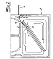
- Fig. 2
- den Gegenstand nach Fig. 1 nach Unterbringung auf den Rohbau einer Schiebetür,
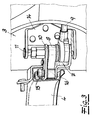
- Fig. 3
- einen vergrößerten Ausschnitt aus dem Gegenstand nach Fig. 2 auf der anderen Türseite,
- Fig. 4
- den Laufwagen aus dem Gegenstand nach Fig. 3 in perspektivischer Darstellung und
- Fig. 5
- einen teilweisen und schematischen Vertikalschnitt durch den Gegenstand nach Fig. 4 im Bereich der Zahnradlagerung.
Claims (9)
- Schiebetürantrieb für die Schiebetür eines Kraftfahrzeuges, wobei die Schiebetür unter Zwischenschaltung zumindest eines Laufwagens an einer karosserieseitigen Führungsschiene geführt ist und der Laufwagen mittels eines Antriebsaggregates mit Antriebsmotor, Getriebe und Antriebsriemen angetrieben ist, dadurch gekennzeichnet, dass der Laufwagen (3) und das Antriebsaggregat (5) an der Schiebetür (2) befestigt sind.
- Schiebetürantrieb nach Anspruch 1, dadurch gekennzeichnet, dass das Antriebsaggregat (5) einen Antriebsmotor (6), z. B. Elektromotor mit einer flexiblen Welle (9) aufweist, die auf das Getriebe (7) arbeitet.
- Schiebetürantrieb nach Anspruch 1 oder 2, dadurch gekennzeichnet, dass das Getriebe (7) um die Schwenkachse des Laufwagens (3) gelagert ist, ein mit einem Zahnrad (10) kämmendes Schneckenrad aufweist, und dass das Schneckenrad vollständig gekapselt ist.
- Schiebetürantrieb nach einem der Ansprüche 1 bis 3, dadurch gekennzeichnet, dass das Zahnrad (10) mit dem Antriebsriemen (8) in Eingriff steht.
- Schiebetürantrieb nach einem der Ansprüche 1 bis 4, dadurch gekennzeichnet, dass das Zahnrad (10) auf einer Lagerachse (11) unter Zwischenschaltung von einem oder mehreren Wälzlagern (12), z. B. Kugellagern gelagert ist.
- Schiebetürantrieb nach einem der Ansprüche 1 bis 5, dadurch gekennzeichnet, dass das Zahnrad (10) mittels zwei im vorgegebenen Abstand voneinander angeordneten Wälzlagern (12) und mittels einer zwischen den beiden Wälzlagern angeordneten Lagerbuchse (13) auf der Lagerachse (11) gelagert ist.
- Schiebetürantrieb nach einem der Ansprüche 1 bis 6, dadurch gekennzeichnet, dass der Laufwagen (3) eine U-förmige Halterung (14) für die Lagerachse (11) aufweist, die in den beiden U-Schenkeln befestigt, z. B. vernietet ist.
- Schiebetürantrieb nach einem der Ansprüche 1 bis 7, dadurch gekennzeichnet, dass der Laufwagen (3) Laufrollen (15) für die Führungsschiene (4) und Umlenkrollen (16) für den karosserieseitig angeschlossenen Antriebsriemen (8) aufweist.
- Schiebetürantrieb nach einem der Ansprüche 1 bis 8, dadurch gekennzeichnet, dass der Antriebsriemen (8) als Zahnriemen ausgebildet ist.
Applications Claiming Priority (2)
| Application Number | Priority Date | Filing Date | Title |
|---|---|---|---|
| DE10341683 | 2003-09-08 | ||
| DE2003141683 DE10341683A1 (de) | 2003-09-08 | 2003-09-08 | Schiebetürantrieb für die Schiebetür eines Kraftfahrzeuges |
Publications (2)
| Publication Number | Publication Date |
|---|---|
| EP1512822A1 true EP1512822A1 (de) | 2005-03-09 |
| EP1512822B1 EP1512822B1 (de) | 2007-05-23 |
Family
ID=34129729
Family Applications (1)
| Application Number | Title | Priority Date | Filing Date |
|---|---|---|---|
| EP20040021260 Expired - Lifetime EP1512822B1 (de) | 2003-09-08 | 2004-09-08 | Schiebetürantrieb für die Schiebetür eines Kraftfahrzeuges |
Country Status (2)
| Country | Link |
|---|---|
| EP (1) | EP1512822B1 (de) |
| DE (2) | DE10341683A1 (de) |
Citations (4)
| Publication number | Priority date | Publication date | Assignee | Title |
|---|---|---|---|---|
| EP1004738A2 (de) * | 1998-11-27 | 2000-05-31 | Lunke Ventra Automotive GmbH | Schiebetür mit Schienenführung und einer Verriegelungsvorrichtung |
| US6079767A (en) * | 1999-06-29 | 2000-06-27 | Daimlerchrysler Corporation | Power sliding door for a motor vehicle |
| US20030116995A1 (en) * | 2001-11-15 | 2003-06-26 | Hiroyuki Yogo | Door apparatus for a vehicle |
| EP1380718A1 (de) * | 2002-07-08 | 2004-01-14 | Delphi Technologies, Inc. | Vorrichtung zur automatischen Betätigung einer Kraftfahrzeugschiebetür |
-
2003
- 2003-09-08 DE DE2003141683 patent/DE10341683A1/de not_active Withdrawn
-
2004
- 2004-09-08 DE DE200450003864 patent/DE502004003864D1/de not_active Expired - Lifetime
- 2004-09-08 EP EP20040021260 patent/EP1512822B1/de not_active Expired - Lifetime
Patent Citations (4)
| Publication number | Priority date | Publication date | Assignee | Title |
|---|---|---|---|---|
| EP1004738A2 (de) * | 1998-11-27 | 2000-05-31 | Lunke Ventra Automotive GmbH | Schiebetür mit Schienenführung und einer Verriegelungsvorrichtung |
| US6079767A (en) * | 1999-06-29 | 2000-06-27 | Daimlerchrysler Corporation | Power sliding door for a motor vehicle |
| US20030116995A1 (en) * | 2001-11-15 | 2003-06-26 | Hiroyuki Yogo | Door apparatus for a vehicle |
| EP1380718A1 (de) * | 2002-07-08 | 2004-01-14 | Delphi Technologies, Inc. | Vorrichtung zur automatischen Betätigung einer Kraftfahrzeugschiebetür |
Also Published As
| Publication number | Publication date |
|---|---|
| DE502004003864D1 (de) | 2007-07-05 |
| DE10341683A1 (de) | 2005-03-31 |
| EP1512822B1 (de) | 2007-05-23 |
Similar Documents
| Publication | Publication Date | Title |
|---|---|---|
| DE102008062763B3 (de) | Koordinatenmessgerät mit einem Antrieb für ein vertikal bewegliches Bauteil des Koordinatenmessgerätes | |
| DE102007045882A1 (de) | Riemengetriebene fremdkraftbetätigte Schiebetür mit Zahnstangengetriebe | |
| DE4428262C1 (de) | Motorisch angetriebener Fensterheber | |
| DE3431324C2 (de) | ||
| EP1512822B1 (de) | Schiebetürantrieb für die Schiebetür eines Kraftfahrzeuges | |
| DE4008061A1 (de) | Vorrichtung zum bewegen verschiebbarer teile | |
| DE102004027064A1 (de) | Zugmitteltrieb für eine Brennkraftmaschine | |
| DE29713290U1 (de) | Rollenbandförderanlage | |
| DE3136890C2 (de) | Motorbetätigter Fensterheber | |
| DE3816864A1 (de) | Spannvorrichtung fuer einen kettentrieb | |
| DE102007049911A1 (de) | Spann- und Führungsschiene für Kettentriebe | |
| DE102020102828B4 (de) | Raupenantrieb für lagerfahrzeug | |
| DE102004013207A1 (de) | Spann- oder Gleitschiene für Kettentriebe von Brennkraftmaschinen von Kraftfahrzeugen | |
| DE19720861A1 (de) | Vorrichtung zum Dehnungsausgleich eines Antriebszugmittels eines linear bewegten Wagens, Schlitten od. dgl. | |
| DE3151652A1 (de) | Umlenk- und fuehrungseinrichtung fuer endlosraeum- und foerderketten von gleisbaumaschinen | |
| DE102004027055A1 (de) | Kostenoptimierter Zugmitteltrieb | |
| DE19509871A1 (de) | Antriebseinrichtung | |
| DE202013005727U1 (de) | Kinderfahrzeug | |
| DE19852950C1 (de) | Schienenbohrvorrichtung | |
| EP1356889B1 (de) | Schweissdrahtvorschubvorrichtung mit mindestens zwei durch ein Schneckengetriebe angetriebenen Rollen | |
| EP1767818A2 (de) | Zahnrad | |
| DE10324323A1 (de) | Antriebsvorrichtung zum Verschieben der Schiebetür eines Kraftfahrzeuges | |
| DE2909856A1 (de) | Antriebsvorrichtung einer bergwerksmaschine | |
| DE2508069A1 (de) | Befoerderungsanlage fuer grubenfoerdermaschinen | |
| WO2004088095A1 (de) | Antriebsvorrichtung an einer brennkraftmaschine |
Legal Events
| Date | Code | Title | Description |
|---|---|---|---|
| PUAI | Public reference made under article 153(3) epc to a published international application that has entered the european phase |
Free format text: ORIGINAL CODE: 0009012 |
|
| AK | Designated contracting states |
Kind code of ref document: A1 Designated state(s): AT BE BG CH CY CZ DE DK EE ES FI FR GB GR HU IE IT LI LU MC NL PL PT RO SE SI SK TR |
|
| AX | Request for extension of the european patent |
Extension state: AL HR LT LV MK |
|
| 17P | Request for examination filed |
Effective date: 20050818 |
|
| AKX | Designation fees paid |
Designated state(s): DE FR IT |
|
| GRAP | Despatch of communication of intention to grant a patent |
Free format text: ORIGINAL CODE: EPIDOSNIGR1 |
|
| GRAS | Grant fee paid |
Free format text: ORIGINAL CODE: EPIDOSNIGR3 |
|
| GRAA | (expected) grant |
Free format text: ORIGINAL CODE: 0009210 |
|
| AK | Designated contracting states |
Kind code of ref document: B1 Designated state(s): DE FR IT |
|
| REF | Corresponds to: |
Ref document number: 502004003864 Country of ref document: DE Date of ref document: 20070705 Kind code of ref document: P |
|
| ET | Fr: translation filed | ||
| PLBE | No opposition filed within time limit |
Free format text: ORIGINAL CODE: 0009261 |
|
| STAA | Information on the status of an ep patent application or granted ep patent |
Free format text: STATUS: NO OPPOSITION FILED WITHIN TIME LIMIT |
|
| 26N | No opposition filed |
Effective date: 20080226 |
|
| PG25 | Lapsed in a contracting state [announced via postgrant information from national office to epo] |
Ref country code: IT Free format text: LAPSE BECAUSE OF FAILURE TO SUBMIT A TRANSLATION OF THE DESCRIPTION OR TO PAY THE FEE WITHIN THE PRESCRIBED TIME-LIMIT Effective date: 20070523 |
|
| REG | Reference to a national code |
Ref country code: FR Ref legal event code: PLFP Year of fee payment: 13 |
|
| REG | Reference to a national code |
Ref country code: FR Ref legal event code: PLFP Year of fee payment: 14 |
|
| REG | Reference to a national code |
Ref country code: FR Ref legal event code: PLFP Year of fee payment: 15 |
|
| P01 | Opt-out of the competence of the unified patent court (upc) registered |
Effective date: 20230529 |
|
| PGFP | Annual fee paid to national office [announced via postgrant information from national office to epo] |
Ref country code: FR Payment date: 20230919 Year of fee payment: 20 Ref country code: DE Payment date: 20230919 Year of fee payment: 20 |
|
| REG | Reference to a national code |
Ref country code: DE Ref legal event code: R071 Ref document number: 502004003864 Country of ref document: DE |