EP1512819B1 - Device for the fixing of a lid to a vehicle - Google Patents
Device for the fixing of a lid to a vehicle Download PDFInfo
- Publication number
- EP1512819B1 EP1512819B1 EP04104050.2A EP04104050A EP1512819B1 EP 1512819 B1 EP1512819 B1 EP 1512819B1 EP 04104050 A EP04104050 A EP 04104050A EP 1512819 B1 EP1512819 B1 EP 1512819B1
- Authority
- EP
- European Patent Office
- Prior art keywords
- arms
- hood
- lid
- arm
- spring
- Prior art date
- Legal status (The legal status is an assumption and is not a legal conclusion. Google has not performed a legal analysis and makes no representation as to the accuracy of the status listed.)
- Expired - Lifetime
Links
- 238000010276 construction Methods 0.000 claims 2
- 230000001419 dependent effect Effects 0.000 description 2
- 238000011161 development Methods 0.000 description 2
- 230000018109 developmental process Effects 0.000 description 2
- 230000000712 assembly Effects 0.000 description 1
- 238000000429 assembly Methods 0.000 description 1
- 230000000295 complement effect Effects 0.000 description 1
- 230000007423 decrease Effects 0.000 description 1
- 238000012986 modification Methods 0.000 description 1
- 230000004048 modification Effects 0.000 description 1
Images


Classifications
-
- E—FIXED CONSTRUCTIONS
- E05—LOCKS; KEYS; WINDOW OR DOOR FITTINGS; SAFES
- E05F—DEVICES FOR MOVING WINGS INTO OPEN OR CLOSED POSITION; CHECKS FOR WINGS; WING FITTINGS NOT OTHERWISE PROVIDED FOR, CONCERNED WITH THE FUNCTIONING OF THE WING
- E05F1/00—Closers or openers for wings, not otherwise provided for in this subclass
- E05F1/08—Closers or openers for wings, not otherwise provided for in this subclass spring-actuated, e.g. for horizontally sliding wings
- E05F1/10—Closers or openers for wings, not otherwise provided for in this subclass spring-actuated, e.g. for horizontally sliding wings for swinging wings, e.g. counterbalance
- E05F1/12—Mechanisms in the shape of hinges or pivots, operated by springs
- E05F1/1207—Mechanisms in the shape of hinges or pivots, operated by springs with a coil spring parallel with the pivot axis
-
- B—PERFORMING OPERATIONS; TRANSPORTING
- B62—LAND VEHICLES FOR TRAVELLING OTHERWISE THAN ON RAILS
- B62D—MOTOR VEHICLES; TRAILERS
- B62D25/00—Superstructure or monocoque structure sub-units; Parts or details thereof not otherwise provided for
- B62D25/08—Front or rear portions
- B62D25/10—Bonnets or lids, e.g. for trucks, tractors, busses, work vehicles
-
- E—FIXED CONSTRUCTIONS
- E05—LOCKS; KEYS; WINDOW OR DOOR FITTINGS; SAFES
- E05C—BOLTS OR FASTENING DEVICES FOR WINGS, SPECIALLY FOR DOORS OR WINDOWS
- E05C17/00—Devices for holding wings open; Devices for limiting opening of wings or for holding wings open by a movable member extending between frame and wing; Braking devices, stops or buffers, combined therewith
- E05C17/02—Devices for holding wings open; Devices for limiting opening of wings or for holding wings open by a movable member extending between frame and wing; Braking devices, stops or buffers, combined therewith by mechanical means
- E05C17/04—Devices for holding wings open; Devices for limiting opening of wings or for holding wings open by a movable member extending between frame and wing; Braking devices, stops or buffers, combined therewith by mechanical means with a movable bar or equivalent member extending between frame and wing
- E05C17/32—Devices for holding wings open; Devices for limiting opening of wings or for holding wings open by a movable member extending between frame and wing; Braking devices, stops or buffers, combined therewith by mechanical means with a movable bar or equivalent member extending between frame and wing consisting of two or more pivoted rods
- E05C17/34—Devices for holding wings open; Devices for limiting opening of wings or for holding wings open by a movable member extending between frame and wing; Braking devices, stops or buffers, combined therewith by mechanical means with a movable bar or equivalent member extending between frame and wing consisting of two or more pivoted rods with means for holding in more than one position
- E05C17/345—Devices for holding wings open; Devices for limiting opening of wings or for holding wings open by a movable member extending between frame and wing; Braking devices, stops or buffers, combined therewith by mechanical means with a movable bar or equivalent member extending between frame and wing consisting of two or more pivoted rods with means for holding in more than one position using friction, e.g. friction hinge
-
- E—FIXED CONSTRUCTIONS
- E05—LOCKS; KEYS; WINDOW OR DOOR FITTINGS; SAFES
- E05F—DEVICES FOR MOVING WINGS INTO OPEN OR CLOSED POSITION; CHECKS FOR WINGS; WING FITTINGS NOT OTHERWISE PROVIDED FOR, CONCERNED WITH THE FUNCTIONING OF THE WING
- E05F1/00—Closers or openers for wings, not otherwise provided for in this subclass
- E05F1/08—Closers or openers for wings, not otherwise provided for in this subclass spring-actuated, e.g. for horizontally sliding wings
- E05F1/10—Closers or openers for wings, not otherwise provided for in this subclass spring-actuated, e.g. for horizontally sliding wings for swinging wings, e.g. counterbalance
- E05F1/1008—Closers or openers for wings, not otherwise provided for in this subclass spring-actuated, e.g. for horizontally sliding wings for swinging wings, e.g. counterbalance with a coil spring parallel with the pivot axis
-
- E—FIXED CONSTRUCTIONS
- E05—LOCKS; KEYS; WINDOW OR DOOR FITTINGS; SAFES
- E05Y—INDEXING SCHEME ASSOCIATED WITH SUBCLASSES E05D AND E05F, RELATING TO CONSTRUCTION ELEMENTS, ELECTRIC CONTROL, POWER SUPPLY, POWER SIGNAL OR TRANSMISSION, USER INTERFACES, MOUNTING OR COUPLING, DETAILS, ACCESSORIES, AUXILIARY OPERATIONS NOT OTHERWISE PROVIDED FOR, APPLICATION THEREOF
- E05Y2201/00—Constructional elements; Accessories therefor
- E05Y2201/40—Motors; Magnets; Springs; Weights; Accessories therefor
- E05Y2201/404—Function thereof
- E05Y2201/416—Function thereof for counterbalancing
-
- E—FIXED CONSTRUCTIONS
- E05—LOCKS; KEYS; WINDOW OR DOOR FITTINGS; SAFES
- E05Y—INDEXING SCHEME ASSOCIATED WITH SUBCLASSES E05D AND E05F, RELATING TO CONSTRUCTION ELEMENTS, ELECTRIC CONTROL, POWER SUPPLY, POWER SIGNAL OR TRANSMISSION, USER INTERFACES, MOUNTING OR COUPLING, DETAILS, ACCESSORIES, AUXILIARY OPERATIONS NOT OTHERWISE PROVIDED FOR, APPLICATION THEREOF
- E05Y2201/00—Constructional elements; Accessories therefor
- E05Y2201/40—Motors; Magnets; Springs; Weights; Accessories therefor
- E05Y2201/47—Springs
- E05Y2201/482—Ribbon springs
-
- E—FIXED CONSTRUCTIONS
- E05—LOCKS; KEYS; WINDOW OR DOOR FITTINGS; SAFES
- E05Y—INDEXING SCHEME ASSOCIATED WITH SUBCLASSES E05D AND E05F, RELATING TO CONSTRUCTION ELEMENTS, ELECTRIC CONTROL, POWER SUPPLY, POWER SIGNAL OR TRANSMISSION, USER INTERFACES, MOUNTING OR COUPLING, DETAILS, ACCESSORIES, AUXILIARY OPERATIONS NOT OTHERWISE PROVIDED FOR, APPLICATION THEREOF
- E05Y2201/00—Constructional elements; Accessories therefor
- E05Y2201/40—Motors; Magnets; Springs; Weights; Accessories therefor
- E05Y2201/47—Springs
- E05Y2201/484—Torsion springs
-
- E—FIXED CONSTRUCTIONS
- E05—LOCKS; KEYS; WINDOW OR DOOR FITTINGS; SAFES
- E05Y—INDEXING SCHEME ASSOCIATED WITH SUBCLASSES E05D AND E05F, RELATING TO CONSTRUCTION ELEMENTS, ELECTRIC CONTROL, POWER SUPPLY, POWER SIGNAL OR TRANSMISSION, USER INTERFACES, MOUNTING OR COUPLING, DETAILS, ACCESSORIES, AUXILIARY OPERATIONS NOT OTHERWISE PROVIDED FOR, APPLICATION THEREOF
- E05Y2201/00—Constructional elements; Accessories therefor
- E05Y2201/60—Suspension or transmission members; Accessories therefor
- E05Y2201/604—Transmission members
-
- E—FIXED CONSTRUCTIONS
- E05—LOCKS; KEYS; WINDOW OR DOOR FITTINGS; SAFES
- E05Y—INDEXING SCHEME ASSOCIATED WITH SUBCLASSES E05D AND E05F, RELATING TO CONSTRUCTION ELEMENTS, ELECTRIC CONTROL, POWER SUPPLY, POWER SIGNAL OR TRANSMISSION, USER INTERFACES, MOUNTING OR COUPLING, DETAILS, ACCESSORIES, AUXILIARY OPERATIONS NOT OTHERWISE PROVIDED FOR, APPLICATION THEREOF
- E05Y2201/00—Constructional elements; Accessories therefor
- E05Y2201/60—Suspension or transmission members; Accessories therefor
- E05Y2201/606—Accessories therefor
- E05Y2201/62—Synchronisation of suspension or transmission members
-
- E—FIXED CONSTRUCTIONS
- E05—LOCKS; KEYS; WINDOW OR DOOR FITTINGS; SAFES
- E05Y—INDEXING SCHEME ASSOCIATED WITH SUBCLASSES E05D AND E05F, RELATING TO CONSTRUCTION ELEMENTS, ELECTRIC CONTROL, POWER SUPPLY, POWER SIGNAL OR TRANSMISSION, USER INTERFACES, MOUNTING OR COUPLING, DETAILS, ACCESSORIES, AUXILIARY OPERATIONS NOT OTHERWISE PROVIDED FOR, APPLICATION THEREOF
- E05Y2201/00—Constructional elements; Accessories therefor
- E05Y2201/60—Suspension or transmission members; Accessories therefor
- E05Y2201/622—Suspension or transmission members elements
- E05Y2201/624—Arms
-
- E—FIXED CONSTRUCTIONS
- E05—LOCKS; KEYS; WINDOW OR DOOR FITTINGS; SAFES
- E05Y—INDEXING SCHEME ASSOCIATED WITH SUBCLASSES E05D AND E05F, RELATING TO CONSTRUCTION ELEMENTS, ELECTRIC CONTROL, POWER SUPPLY, POWER SIGNAL OR TRANSMISSION, USER INTERFACES, MOUNTING OR COUPLING, DETAILS, ACCESSORIES, AUXILIARY OPERATIONS NOT OTHERWISE PROVIDED FOR, APPLICATION THEREOF
- E05Y2201/00—Constructional elements; Accessories therefor
- E05Y2201/60—Suspension or transmission members; Accessories therefor
- E05Y2201/622—Suspension or transmission members elements
- E05Y2201/686—Rods, links
-
- E—FIXED CONSTRUCTIONS
- E05—LOCKS; KEYS; WINDOW OR DOOR FITTINGS; SAFES
- E05Y—INDEXING SCHEME ASSOCIATED WITH SUBCLASSES E05D AND E05F, RELATING TO CONSTRUCTION ELEMENTS, ELECTRIC CONTROL, POWER SUPPLY, POWER SIGNAL OR TRANSMISSION, USER INTERFACES, MOUNTING OR COUPLING, DETAILS, ACCESSORIES, AUXILIARY OPERATIONS NOT OTHERWISE PROVIDED FOR, APPLICATION THEREOF
- E05Y2900/00—Application of doors, windows, wings or fittings thereof
- E05Y2900/50—Application of doors, windows, wings or fittings thereof for vehicles
- E05Y2900/53—Type of wing
- E05Y2900/536—Hoods
Definitions
- the invention relates to a device for attaching a hood to a vehicle, which covers an engine of the vehicle and other components of the vehicle.
- the vehicle is an agricultural or industrial utility vehicle.
- the rear end of a hood of an agricultural utility vehicle, in particular a tractor, is subject to constraints in the spatial design, namely, it must have a narrow width to ensure sufficient visibility.
- the WO 02/22431 shows a support device for a hood with a first arm pair and a second arm pair, which are pivotally connected to each other via a hinge.
- the first arm pair is pivotally attached to the engine.
- the second Arm pair is pivotally connected to a rod, wherein the rod is connected at one end to the engine and at the other end to the hood.
- Both arm pairs are acted upon in the region of the joint by a torsion spring to take a splayed position. As a result, an opening movement is transmitted to the hood over the rod.
- Both arm pairs have in the region of their articulated connection for receiving the torsion spring a maximum lateral width, which decreases toward the respective ends of a pair of arms out.
- the DE 102 29 766 A1 shows a support device for a hood on which a holder is mounted in a central lower region.
- An arm is pivotally held on the one hand on the bracket and on the other hand pivotally supported on a support bracket connected to the motor.
- a spring linkage assembly is arranged, comprising two by means of a coil spring against each other biased rod pairs, consisting of first arms and second arms.
- the first end of the first arm is pivotally mounted on the arm.
- the coil spring acts indirectly on the arm so that the bonnet is lifted over it.
- a telescopic damper is provided, which is arranged between the holder and the arm.
- the object underlying the invention is seen to provide and develop a device for supporting a hood, which avoids the use of gas springs, which in particular requires no latching device or no separate fork support.
- the device according to the invention is suitable for fastening, carrying and / or moving a hood relative to a vehicle, wherein the hood is rotatably attachable to the vehicle.
- the device comprises two - preferably laterally spaced - arranged first arms, two - preferably in the lateral direction - spaced from each other arranged second arms and an elastic and / or resilient means.
- a first arm has a first end and a second end. The first end of the first arm is rotatably / pivotally mounted on the vehicle.
- a second arm has a first end rotatably disposed at a second end of a first arm.
- a second arm has a second end for connection to the hood and for supporting the hood.
- the resilient means is disposed between the first and second arms and tensioned to urge the second ends of the second arms upwardly and toward the hood, the lateral distance between the first ends of the first arms being greater than the lateral distance between the second ends of the first arms and the first ends of the second arms.
- a pivot pin couples a second arm to a first arm.
- the elastic and / or resilient device is arranged or wound around the pivot pin.
- the pivot pin is non-rotatably attached to at least one of the second arms.
- the elastic and / or resilient device has an inner End mounted on the pivot pin.
- the elastic and / or resilient device has an outer end which is rotatably attached to at least one first arm.
- the elastic and / or resilient means could comprise a torsion spring or a torsion spring.
- the lateral distance between the second ends of the second arms could be greater than the lateral distance between the second ends of the first arms and the first ends of the second arms. As a result, the torsional stiffness of the hood and the space under the hood can be increased.
- the lateral distance between the first arms is maintainable by means of a strut, wherein the strut between the first arms can be fastened. So could also be maintained by means of a strut, the lateral distance between the second arms, wherein the strut would be to be fastened between the second arms.
- a joint support is provided, on which the hood is rotatably arranged and / or on which the first arms rotatable can be arranged.
- the joint carrier could be fastened to a frame of the vehicle.
- the hood is mountable on a hood support structure, wherein the hood support structure at a first location on the hinge support is rotatably arranged.
- the hood support structure is attachable to the second arm at a second location.
- the inventive device for attaching a hood is generally used to support the hood in the raised or opened position relative to the vehicle to which the hood is rotatably coupled.
- the device comprises two pairs of arm parts, which are rotatably coupled to each other via a pivot pin and which are arranged between the vehicle and the vehicle hood.
- a flat coiled spring or torsion spring is wound around the pivot pin and is secured to the arm parts. The spring is biased to rotate a pair of arms, thereby urging the hood upwardly.
- the device according to the invention for attaching a hood avoids the use of gas springs. It has a very long life in a particularly advantageous manner and no latching mechanism or separate fork support is required to hold the hood in its open position.
- the device according to the invention takes up little space, in particular in the closed state of the hood, so that in a particularly advantageous manner, the space covered by the hood can be optimally utilized, for example for hydraulic lines and other components or components of the Vehicle.
- the device according to the invention has a very high torsional stiffness, which can be largely avoided when closing the hood in an advantageous manner damage to the hood or to be covered by the hood vehicle components.
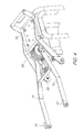
- Fig. 1 is an embodiment of a device according to the invention for wearing a hood indicated by the reference numeral 10.
- the device 10 comprises a hood arm device 12, a spring arm device 14 and a spring device 16.
- the hood arm device 12 comprises two hood arms 18, which are joined together by a strut 20.
- Each hood arm 18 includes a first portion 22, a second portion 24 that is angled toward the first portion 22, and a third portion 26 that is angled toward the second portion 24.
- the first portion 22 and the third portion 26 are arranged substantially parallel to each other.
- the strut 20 is welded or otherwise secured to the second portion 24 of the hood arms 18 and keeps the hood arms 18 spaced apart such that the first portions 22 and the third portions 26 are each disposed parallel to each other. Due to the provided angle between the individual sections 22, 24 and 26 of the hood arms 18, the distance between the ends 28 of the hood arms 18 is substantially greater than the distance between the first ends 26 of the hood arms 18. Flanges 32 for attaching the hood are rotatable arranged the ends 28 of the hood arms 18, so that the hood arms 18 can be easily attached to the hood of a vehicle.
- the first ends 26 of the hood arms 18 further include a first bore 34 and a second bore 36, respectively.
- the spring arm assembly 14 includes two spring arms 38 and a strut 40.
- Each spring arm 38 is substantially characterized by a first portion 42, a second portion 44 disposed at an angle to the first portion 42, and a third portion 46 which under is arranged at an angle to the second portion 44.
- the first portion 42 includes a bore 48 and a semicircular aperture 50.
- the second portion 44 includes two apertures 52 for securing the strut 40.
- the third portion 46 includes an aperture 54 for attaching an arm.
- the strut 40 includes end portions 55A and 55B and a central portion 56.
- the end portions 55A and 55B of the strut 40 each include apertures 52 corresponding to the apertures 52 of the spring arms 38.
- the end portions 55A and 55B of the strut 40 are disposed at an angle relative to the central portion 56 such that, if spring arms 38 are secured to the strut 40, the spring arms 38 are spaced from each other in a position in which the first portion 42 and the third portion 46 of a spring arm 38 are arranged substantially parallel to the first portion 42 and the third portion 46 of the other spring arm 38.
- the distance between the third portions 46 is greater than the distance between the first portions 42 of the spring arms 38th
- the spring device 16 comprises one or more elastic elements or spring elements 58, which is or are preferably in the form of a tortuous torsion spring or torsion spring.
- Each torsion spring 58 includes a first end, not shown, received between two bolts 60A and 60B having a semicircular cross-section.
- the two semicircular cross-section bolts 60A and 60B together form a center pivot pin 60.
- Each torsion spring 58 is wound around the center pivot pin 60 in a coiled manner and includes a second end forming a journaled or hooked end 62.
- the end 62 is is formed to abut the flat surface portion 66 of the semicircular cross-section pin 64.
- the device 10 further comprises a hinge carrier 70, which serves as a pivot point for the hood 81, to which the spring arm device 14 is attachable.
- the hinge bracket 70 serves as a means for securing the entire device to a frame of the vehicle.
- the hinge bracket 70 includes an upper end portion 72 having two pivotal apertures 74 and a middle portion 76.
- the hinge bracket 70 has a plurality of apertures 78 for attaching the hinge bracket 70 to the frame of the vehicle.
- the hinge bracket 70 further includes a lower end portion 80 having two apertures 82 for attaching the spring arms 38.
- the hinge bracket 70 is secured to a support portion 83 of the vehicle frame by means of the apertures 78 using suitable bolts or corresponding connection means.
- Fig. 2 It can be seen that the hood 81 is mounted on the hinge support 70 via a hood support structure 84 which is rotatably secured with its one end to the pivot aperture 74 via a corresponding torsion bar 85.
- the spring arms 38 are rotatably mounted on the apertures 82 of the hinge bracket 70 by means of suitable bolts or corresponding connection means.
- the spring unit 16 is mounted between the spring arms 38 such that the ends of the split pivot pin 60 are supported in the spring apertures 48. Bearings could be provided in the apertures 48, which allow free rotation of the split pivot pin 60 relative to the spring arms 38.
- the semi-circular cross-section pin 64 is fixed in the semicircular apertures 50 of the spring arms 38.
- the pin-shaped end 62 of the spring device or the torsion spring 58 abuts against the flat surface 66 of the bolt 64 and comes to rest against it.
- the torsion spring 58 is fixed independently of the split pivot pin 60 against rotation. Accordingly, rotation of the pivot pin 60, which receives the first end of the torsion spring 58, causes the torsion spring 58 to twist or twist depending on the direction of rotation. It does not move rotation of the entire torsion spring 58 because the bolt 64 is a stop or stop for the torsion spring 58.
- the spring arm means 14 and the spring means 16 are held by the laterally spaced third portions 26 of the bonnet arms 18 because the split pivot bolt 60 extends through the first apertures 34 provided on the second end 30 of the bonnet arms 18, respectively. At least one washer 86 is provided for each hood arm 18 having two semicircular apertures 87.
- the semicircular apertures 87 of the washers 86 are sized to complement the semicircular cross-section bolts 60A and 60B which form the split pintle 60.
- the washers 86 are welded to the hood arms 18 at the first apertures 34 or otherwise fixed such that the split pivot pin 60 is fixed or secured against rotation relative to the hood arms 18. Accordingly, the hood arms 18 can rotate only the split pivot pin 60 and vice versa.
- rotation / rotation of the hood arm means 12 relative to the spring arm means 14 necessarily winds or winds the torsion spring 58.
- the hood arms 18 are attached to the hood support structure 84 by means of the mounting flanges 32, which rotate relative to the hood arms 18. Accordingly, the hood support structure 84 is indirectly attached to the vehicle via the hood arms 18 and directly over the hinge bracket 70.
- the hood 81 rotates on the hinge bracket 70 and is thereby assisted by the device 10 for moving the hood 81 when the hood 81 is lifted or opened.
- the torsion spring 58 is biased so that it rotates the spring arms 18 upwards, with respect to the figures in the clockwise direction and the hood support structure 84 back.
- the spring arms 38 rotate counterclockwise and forward relative to the figures when the hood 81 is raised, which causes the hood support structure 84 to lift and hold the hood support structure 84 in a raised position, as shown in FIG Fig. 3 is shown.
- a stopper bolt 88 is provided in the second aperture 36 at the second end 30 of the bonnet arms 18 to limit the relative rotation between the bonnet arms 18 and the spring arms 38.
- the spring force of the torsion spring 58 varies slightly with a change in temperature and becomes so is chosen to be sufficient to hold the hood support structure 84 in an open or raised position without the use of an additional fork support or the like.
- the large distance between the first ends 28 of the hood arms 18 and the third portions 46 of the spring arms 38 allow space for hydraulic lines and other components under the hood and significantly increase the torsional rigidity of the hood when the hood is open.
Landscapes
- Engineering & Computer Science (AREA)
- Chemical & Material Sciences (AREA)
- Combustion & Propulsion (AREA)
- Transportation (AREA)
- Mechanical Engineering (AREA)
- Superstructure Of Vehicle (AREA)
Description
Die Erfindung betrifft eine Vorrichtung zum Befestigen einer Haube an einem Fahrzeug, welche einen Motor des Fahrzeugs und andere Komponenten des Fahrzeugs abdeckt. Vorzugsweise handelt es sich bei dem Fahrzeug um ein landwirtschaftliches oder industrielles Nutzfahrzeug. Das hintere Ende einer Haube eines landwirtschaftlichen Nutzfahrzeugs, insbesondere eines Traktors, unterliegt Zwängen in der räumlichen Ausgestaltung, es muss nämlich zur Gewährleistung einer ausreichenden Sicht eine geringe Breite aufweisen.The invention relates to a device for attaching a hood to a vehicle, which covers an engine of the vehicle and other components of the vehicle. Preferably, the vehicle is an agricultural or industrial utility vehicle. The rear end of a hood of an agricultural utility vehicle, in particular a tractor, is subject to constraints in the spatial design, namely, it must have a narrow width to ensure sufficient visibility.
Aus dem Stand der Technik ist der Einsatz von Gasfedern zum Tragen bzw. Unterstützen einer Fahrzeughaube/Motorhaube bekannt. Solche Fahrzeughauben sind lang und schwer und erfordern eine erhebliche Kraft, um die Haube in einer geöffneten Position zu halten bzw. zu balancieren. Gasfedern ermöglichen eine kompakte Bauweise im Inneren der Haube, sie neigen jedoch dazu, zu versagen, wenn ihre Gasladung sich abnutzt oder verloren geht. Weiterhin ist ihre Federkraft abhängig von der Variation der Umgebungstemperatur. Schließlich liefert die Verwendung von Gasfedern auf jeder Seite der Haube keine ausreichende Steifigkeit gegen Torsion, welche auf die Haube durch Wind oder von einer seitwärtsgerichteten Kraft vom Schließen der Haube hervorgerufen wird, wenn der Bediener neben der Haube steht. Andere aus dem Stand der Technik bekannte Trägervorrichtungen für Hauben erfordern des Weiteren eine Einrastvorrichtung oder eine separate Gabelstütze, um eine Haube in einer angehobenen oder geöffneten Position zu halten.From the prior art, the use of gas springs for supporting or supporting a vehicle hood / hood is known. Such vehicle hoods are long and heavy and require considerable force to hold the hood in an open position. Gas springs allow a compact design inside the hood, but they tend to fail when their gas charge wears or gets lost. Furthermore, their spring force is dependent on the variation of the ambient temperature. Finally, the use of gas springs on either side of the hood does not provide sufficient torsional stiffness, which is caused to the hood by wind or by a sideways force from closing the hood when the operator is standing next to the hood. Other hood support devices known in the art further require a latch or separate fork support to hold a hood in a raised or open position.
Die
Die
Die der Erfindung zugrunde liegende Aufgabe wird darin gesehen, eine Vorrichtung zum Tragen einer Haube anzugeben und weiterzubilden, welche eine Verwendung von Gasfedern vermeidet, welche insbesondere keine Einrastvorrichtung oder keine separate Gabelstütze erfordert.The object underlying the invention is seen to provide and develop a device for supporting a hood, which avoids the use of gas springs, which in particular requires no latching device or no separate fork support.
Die Aufgabe wird erfindungsgemäß durch die Lehre des Patentanspruchs 1 gelöst. Weitere vorteilhafte Ausgestaltungen und Weiterbildungen der Erfindung gehen aus den Unteransprüchen hervor.The object is achieved by the teaching of claim 1. Further advantageous embodiments and further developments of the invention will become apparent from the dependent claims.
Die erfindungsgemäße Vorrichtung ist zum Befestigen, Tragen und/oder Bewegen einer Haube relativ zu einem Fahrzeug geeignet, wobei die Haube drehbar an dem Fahrzeug anbringbar ist. Die Vorrichtung umfasst zwei - vorzugsweise in lateraler Richtung - voneinander beabstandet angeordnete erste Arme, zwei - vorzugsweise in lateraler Richtung - voneinander beabstandet angeordnete zweite Arme und eine elastische und/oder federnde Einrichtung. Ein erster Arm weist ein erstes Ende und ein zweites Ende auf. Das erste Ende des ersten Arms ist drehbar/schwenkbar an dem Fahrzeug angeordnet. Ein zweiter Arm weist ein erstes Ende auf, welches drehbar an einem zweiten Ende eines ersten Arms angeordnet ist. Ein zweiter Arm weist ein zweites Ende zum Verbinden mit der Haube und zum Unterstützen der Haube auf. Die elastische/federnde Einrichtung ist zwischen den ersten und zweiten Armen angeordnet und gespannt, um die zweiten Enden der zweiten Arme nach oben und zu der Haube hin zu drängen, wobei der laterale Abstand zwischen den ersten Enden der ersten Arme größer als der laterale Abstand zwischen den zweiten Enden der ersten Arme und der ersten Enden der zweiten Arme. Hierdurch ist die Torsionssteifigkeit der Haube und der Bauraum unter der Haube erhöhbar.The device according to the invention is suitable for fastening, carrying and / or moving a hood relative to a vehicle, wherein the hood is rotatably attachable to the vehicle. The device comprises two - preferably laterally spaced - arranged first arms, two - preferably in the lateral direction - spaced from each other arranged second arms and an elastic and / or resilient means. A first arm has a first end and a second end. The first end of the first arm is rotatably / pivotally mounted on the vehicle. A second arm has a first end rotatably disposed at a second end of a first arm. A second arm has a second end for connection to the hood and for supporting the hood. The resilient means is disposed between the first and second arms and tensioned to urge the second ends of the second arms upwardly and toward the hood, the lateral distance between the first ends of the first arms being greater than the lateral distance between the second ends of the first arms and the first ends of the second arms. As a result, the torsional stiffness of the hood and the space under the hood can be increased.
Bevorzugt koppelt ein Drehbolzen einen zweiten Arm an einen ersten Arm. Die elastische und/oder federnde Einrichtung ist um den Drehbolzen herum angeordnet bzw. gewunden.Preferably, a pivot pin couples a second arm to a first arm. The elastic and / or resilient device is arranged or wound around the pivot pin.
In einer bevorzugten Ausführungsform ist der Drehbolzen drehfest an mindestens einem der zweiten Arme befestigt. Die elastische und/oder federnde Einrichtung weist ein inneres Ende auf, welches an dem Drehbolzen befestigt ist. Die elastische und/oder federnde Einrichtung weist ein äußeres Ende auf, welches an mindestens einem ersten Arm drehfest befestigt ist.In a preferred embodiment, the pivot pin is non-rotatably attached to at least one of the second arms. The elastic and / or resilient device has an inner End mounted on the pivot pin. The elastic and / or resilient device has an outer end which is rotatably attached to at least one first arm.
Im Konkreten könnte die elastische und/oder federnde Einrichtung eine Torsionsfeder oder eine Drehfeder aufweisen.Specifically, the elastic and / or resilient means could comprise a torsion spring or a torsion spring.
Der laterale Abstand zwischen den zweiten Enden der zweiten Arme könnte größer als der laterale Abstand zwischen den zweiten Enden der ersten Arme und den ersten Enden der zweiten Arme sein. Auch hierdurch ist die Torsionssteifigkeit der Haube und der Bauraum unter der Haube erhöhbar.The lateral distance between the second ends of the second arms could be greater than the lateral distance between the second ends of the first arms and the first ends of the second arms. As a result, the torsional stiffness of the hood and the space under the hood can be increased.
Bevorzugte ist mittels einer Strebe der laterale Abstand zwischen den ersten Armen aufrechterhaltbar, wobei die Strebe zwischen den ersten Armen befestigbar ist. So könnte ebenfalls mittels einer Strebe der laterale Abstand zwischen den zweiten Armen aufrechterhaltbar sein, wobei die Strebe zwischen den zweiten Armen zu befestigen wäre.Preferably, the lateral distance between the first arms is maintainable by means of a strut, wherein the strut between the first arms can be fastened. So could also be maintained by means of a strut, the lateral distance between the second arms, wherein the strut would be to be fastened between the second arms.
In einer besonders bevorzugten Ausführungsform ist ein Gelenkträger vorgesehen, an welchem die Haube drehbar anordenbar ist und/oder an welchem die ersten Arme drehbar anordenbar sind. Der Gelenkträger könnte an einem Rahmen des Fahrzeugs befestigbar sein.In a particularly preferred embodiment, a joint support is provided, on which the hood is rotatably arranged and / or on which the first arms rotatable can be arranged. The joint carrier could be fastened to a frame of the vehicle.
Ganz besonders bevorzugt ist die Haube an einer Haubenträgerstruktur montierbar, wobei die Haubenträgerstruktur an einer ersten Stelle an dem Gelenkträger drehbar anordenbar ist. Die Haubenträgerstruktur ist an einer zweiten Stelle an den zweiten Armen befestigbar.Most preferably, the hood is mountable on a hood support structure, wherein the hood support structure at a first location on the hinge support is rotatably arranged. The hood support structure is attachable to the second arm at a second location.
Die erfindungsgemäße Vorrichtung zum Befestigen einer Haube dient ganz Allgemein zur Unterstützung der Haube in der angehobenen bzw. geöffneten Position relativ zu dem Fahrzeug, an welchem die Haube drehbar gekoppelt ist. Die Vorrichtung umfasst zwei Paare von Armteilen, welche über einen Drehbolzen drehbar aneinander gekoppelt sind und welche zwischen dem Fahrzeug und der Fahrzeughaube angeordnet sind. Eine flache gewundene Feder bzw. Torsionsfeder ist um den Drehbolzen gewunden und ist an den Armteilen befestigt. Die Feder ist derart vorgespannt, dass ein Paar von Armen gedreht wird und hierdurch die Haube nach oben gedrängt wird.The inventive device for attaching a hood is generally used to support the hood in the raised or opened position relative to the vehicle to which the hood is rotatably coupled. The device comprises two pairs of arm parts, which are rotatably coupled to each other via a pivot pin and which are arranged between the vehicle and the vehicle hood. A flat coiled spring or torsion spring is wound around the pivot pin and is secured to the arm parts. The spring is biased to rotate a pair of arms, thereby urging the hood upwardly.
Zusammenfassend sei noch einmal hervorgehoben, dass die erfindungsgemäße Vorrichtung zum Befestigen einer Haube eine Verwendung von Gasfedern vermeidet. Sie hat in ganz besonders vorteilhafter Weise eine lange Lebensdauer und es ist kein Einrastmechanismus oder keine separate Gabelstütze erforderlich, um die Haube in ihrer geöffneten Position zu halten. Die erfindungsgemäße Vorrichtung nimmt insbesondere im geschlossenen Zustand der Haube wenig Platz in Anspruch, so dass in besonders vorteilhafter Weise der von der Haube verdeckte Raum optimal genutzt werden kann, beispielsweise für Hydraulikleitungen und andere Bauteile bzw. Komponenten des Fahrzeugs. Auch weist die erfindungsgemäße Vorrichtung eine ganz besonders hohe Torsionssteifigkeit auf, wodurch in vorteilhafter Weise eine Beschädigung der Haube oder der von der Haube abzudeckenden Fahrzeugkomponenten beim Schließen der Haube weitgehend vermieden werden kann.In summary, it should again be emphasized that the device according to the invention for attaching a hood avoids the use of gas springs. It has a very long life in a particularly advantageous manner and no latching mechanism or separate fork support is required to hold the hood in its open position. The device according to the invention takes up little space, in particular in the closed state of the hood, so that in a particularly advantageous manner, the space covered by the hood can be optimally utilized, for example for hydraulic lines and other components or components of the Vehicle. Also, the device according to the invention has a very high torsional stiffness, which can be largely avoided when closing the hood in an advantageous manner damage to the hood or to be covered by the hood vehicle components.
Anhand der Zeichnung, die ein Ausführungsbeispiel der Erfindung zeigt, werden nachfolgend die Erfindung sowie weitere Vorteile und vorteilhafte Weiterbildungen und Ausgestaltungen der Erfindung näher beschrieben und erläutert.Reference to the drawing, which shows an embodiment of the invention, the invention and further advantages and advantageous developments and refinements of the invention are described and explained in more detail below.
Es zeigt jeweils in einer schematischen Darstellung:
- Fig. 1
- eine perspektivische Explosionsansicht eines erfindungsgemäßen Ausführungsbeispiels einer Vorrichtung zum Tragen einer Motorhaube,
- Fig. 2
- eine perspektivische Ansicht einer Haubenanordnung eines Fahrzeugs, von welcher ein Teil ausgeschnitten ist, in welcher eine erfindungsgemäße Vorrichtung zum Tragen einer Motorhaube eingebaut ist,
- Fig. 3
- eine perspektivische Ansicht der erfindungsgemäßen Vorrichtung zum Tragen einer Haube in einer angehobenen Position und
- Fig. 4
- eine perspektivische Ansicht der erfindungsgemäßen Vorrichtung zum Tragen einer Haube in einer abgesenkten Position.
- Fig. 1
- an exploded perspective view of an embodiment of an inventive device for supporting a hood,
- Fig. 2
- a perspective view of a hood assembly of a vehicle, of which a part is cut out, in which a device according to the invention for supporting a hood is installed,
- Fig. 3
- a perspective view of the device according to the invention for supporting a hood in a raised position and
- Fig. 4
- a perspective view of the device according to the invention for supporting a hood in a lowered position.
Unter Bezugnahme auf die Figuren und insbesondere auf
Die Federarmeinrichtung 14 umfasst zwei Federarme 38 und eine Strebe 40. Jeder Federarm 38 ist im Wesentlichen durch einen ersten Abschnitt 42, einen zweiten Abschnitt 44, welcher unter einem Winkel zu dem ersten Abschnitt 42 angeordnet ist, und durch einen dritten Abschnitt 46 charakterisiert, welcher unter einem Winkel zu dem zweiten Abschnitt 44 angeordnet ist. Der erste Abschnitt 42 umfasst eine Bohrung bzw. Federapertur 48 und eine halbkreisförmige Apertur 50. Der zweite Abschnitt 44 umfasst zwei Aperturen 52 zum Befestigen der Strebe 40. Der dritte Abschnitt 46 umfasst eine Apertur 54 zum Befestigen eines Arms. Die Strebe 40 umfasst Endabschnitte 55A und 55B und einen mittleren Abschnitt 56. Die Endabschnitte 55A und 55B der Strebe 40 umfassen jeweils Aperturen 52, welche zu den Aperturen 52 der Federarme 38 korrespondieren. Die Endabschnitte 55A und 55B der Strebe 40 sind unter einem Winkel relativ zum mittleren Abschnitt 56 derart angeordnet, dass, falls Federarme 38 an der Strebe 40 befestigt sind, die Federarme 38 voneinander beabstandet in einer Position gehalten werden, in welcher der erste Abschnitt 42 und der dritte Abschnitt 46 eines Federarms 38 im Wesentlichen parallel zu dem ersten Abschnitt 42 und dem dritten Abschnitt 46 des anderen Federarms 38 angeordnet sind. Im montierten Zustand der Federarme 38 an der Strebe 40 ist der Abstand zwischen den dritten Abschnitten 46 größer als der Abstand zwischen den ersten Abschnitten 42 der Federarme 38.The
Die Federeinrichtung 16 umfasst ein oder mehrere elastische Elemente bzw. Federelemente 58, welche vorzugsweise in Form einer gewundenen Torsionsfeder bzw. Drehfeder ausgebildet ist bzw. sind. Jede Torsionsfeder 58 umfasst ein erstes, nicht gezeigtes Ende, welches zwischen zwei Bolzen 60A und 60B mit einem halbkreisförmigen Querschnitt aufgenommen ist. Die zwei Bolzen 60A und 60B mit dem halbkreisförmigen Querschnitt bilden zusammen einen mittleren Drehbolzen 60. Jede Torsionsfeder 58 ist um den mittleren Drehbolzen 60 in einer übereinandergerollten Weise gewunden und umfasst ein zweites Ende, welches ein zapfen- oder hakenförmiges Ende 62 bildet. Das Ende 62 ist derart ausgebildet, dass es an dem flachen Oberflächenabschnitt 66 des einen halbkreisförmigen Querschnitt aufweisenden Bolzens 64 zur Anlage bzw. zum Anstoß kommt.The
Zu den bisher beschriebenen Einrichtungen bzw. Baugruppen umfasst die Vorrichtung 10 des Weiteren einen Gelenkträger 70, welcher als Dreh- bzw. Schwenkpunkt für die Haube 81 dient, an welchem die Federarmeinrichtung 14 anbringbar ist. Der Gelenkträger 70 dient als ein Mittel zum Befestigen bzw. Sichern der gesamten Einrichtung an einem Rahmen des Fahrzeugs. Der Gelenkträger 70 umfasst einen oberen Endabschnitt 72, der zwei Drehgelenkaperturen 74 und einen mittleren Abschnitt 76 aufweist. Der Gelenkträger 70 weist eine Vielzahl von Aperturen 78 zum Befestigen des Gelenkträgers 70 an dem Rahmen des Fahrzeugs auf. Der Gelenkträger 70 umfasst des Weiteren einen unteren Endabschnitt 80, der zwei Aperturen 82 zum Anbringen der Federarme 38 aufweist. Der Gelenkträger 70 ist an einem Trägerabschnitt 83 des Fahrzeugrahmens mittels der Aperturen 78 gesichert, wobei geeignete Bolzen oder entsprechende Verbindungsmittel verwendet werden.
Im Folgenden wird auf die
Wie bereits beschrieben, sind die Haubenarme 18 an der Haubenträgerstruktur 84 mittels den Befestigungsflanschen 32 angebracht, welche relativ zu den Haubenarmen 18 drehen. Dementsprechend ist die Haubenträgerstruktur 84 indirekt über die Haubenarme 18 und direkt über den Gelenkträger 70 an dem Fahrzeug befestigt. Somit dreht die Haube 81 an dem Gelenkträger 70 und wird hierbei von der Vorrichtung 10 zum Bewegen der Haube 81 unterstützt, wenn die Haube 81 angehoben bzw. geöffnet wird. Im Konkreten ist die Torsionsfeder 58 derart vorgespannt, dass sie die Federarme 18 nach oben, bezogen auf die Figuren im Uhrzeigersinn und zur der Haubenträgerstruktur 84 hin dreht. Hierbei drehen die Federarme 38 bezogen auf die Figuren entgegengesetzt dem Uhrzeigersinn und nach vorne, wenn die Haube 81 angehoben wird, was dazu führt, die Haubenträgerstruktur 84 anzuheben und die Haubenträgerstruktur 84 in einer angehobenen Position zu halten, wie es in
Auch wenn die Erfindung anhand eines Ausführungsbeispiels beschrieben wurde, erschließen sich für den Fachmann im Lichte der vorstehenden Beschreibung sowie der Zeichnung viele verschiedenartige Alternativen, Modifikationen und Varianten, die unter die vorliegende Erfindung fallen.Although the invention has been described with reference to an embodiment, many different alternatives, modifications and variants falling within the scope of the present invention will become apparent to those skilled in the art in light of the above description and the drawings.
Claims (9)
- Device for supporting and/or moving a lid (81) relative to a vehicle to which the lid (81) is rotatably attachable, with two first arms (14) which are arranged spaced apart from each other in the lateral direction, two second arms (18) which are arranged spaced apart from each other in the lateral direction, and an elastic and/or resilient device (58), wherein a first arm (14) referred to has a first end (46) and a second end (42), wherein the first end (46) of the first arm (14) is arranged rotatably/pivotably on the vehicle, wherein a second arm (18) referred to has a first end (26) which is arranged rotatably at the second end (42) of the first arm (14), wherein the second arm (18) has a second end (28) for connecting to the lid and for supporting the lid (81), and wherein the elastic/resilient device (58) is arranged and clamped between the first and second arms (14, 18) in order to push the second ends (28) of the second arms (18) upwards and towards the lid (81), characterized in that the lateral distance between the first ends (46) of the first arms (14) is greater than the lateral distance between the second ends (42) of the first arms (14) and the first ends (26) of the second arms (18), wherein the torsional rigidity of the lid (81) and the construction space under the lid is increasable.
- Device according to Claim 1, wherein a rotary pin (60) couples the second arm (18) to the first arm (14), and wherein the elastic and/or resilient device (58) is arranged or coiled around the rotary pin (60).
- Device according to Claim 2, wherein the rotary pin (60) is fastened in a rotationally fixed manner to at least one of the second arms (18), wherein the elastic and/or resilient device (58) has an inner end which is fastened to the rotary pin (60), and wherein the elastic and/or resilient device (58) has an outer end (62) which is fastened in a rotationally fixed manner to at least one first arm (14).
- Device according to one of Claims 1 to 3, wherein the elastic and/or resilient device (58) has a torsion spring or a leg spring.
- Device according to one of the preceding claims, wherein the lateral distance between the second ends (28) of the second arms (18) is greater than the lateral distance between the second ends (42) of the first arms (14) and the first ends (26) of the second arms (18), wherein the torsional rigidity of the lid (81) and the construction space under the lid is increasable.
- Device according to one of the preceding claims, wherein the lateral distance between the first arms (14) is maintainable by means of a strut (40), and wherein the strut (40) is fastenable between the first arms (14).
- Device according to one of the preceding claims, wherein the lateral distance between the second arms (18) is maintainable by means of a strut (20), and wherein the strut (20) is fastenable between the second arms (18).
- Device according to one of the preceding claims, wherein an articulated support (70) is provided, on which the lid (81) is arrangeable rotatably and/or on which the first arms (14) are arrangeable rotatably, and wherein the articulated support (70) is fastenable preferably to a frame of the vehicle.
- Device according to one of the preceding claims, wherein the lid (81) is mountable on a lid support structure (84), wherein the lid support structure (84) is arrangeable rotatably on the articulated support (70) at a first location, and wherein the lid support structure (84) is fastenable to the second arms (18) at a second location.
Applications Claiming Priority (2)
| Application Number | Priority Date | Filing Date | Title |
|---|---|---|---|
| US649568 | 1991-02-05 | ||
| US10/649,568 US6929279B2 (en) | 2003-08-27 | 2003-08-27 | Hood support mechanism |
Publications (3)
| Publication Number | Publication Date |
|---|---|
| EP1512819A2 EP1512819A2 (en) | 2005-03-09 |
| EP1512819A3 EP1512819A3 (en) | 2009-02-11 |
| EP1512819B1 true EP1512819B1 (en) | 2014-01-08 |
Family
ID=34136622
Family Applications (1)
| Application Number | Title | Priority Date | Filing Date |
|---|---|---|---|
| EP04104050.2A Expired - Lifetime EP1512819B1 (en) | 2003-08-27 | 2004-08-23 | Device for the fixing of a lid to a vehicle |
Country Status (2)
| Country | Link |
|---|---|
| US (1) | US6929279B2 (en) |
| EP (1) | EP1512819B1 (en) |
Families Citing this family (9)
| Publication number | Priority date | Publication date | Assignee | Title |
|---|---|---|---|---|
| US7036618B2 (en) * | 2004-07-01 | 2006-05-02 | Cnh America Llc | Hood assembly |
| JP4197670B2 (en) * | 2004-08-24 | 2008-12-17 | ヤンマー株式会社 | Loader tractor bonnet |
| US7540345B2 (en) * | 2006-01-26 | 2009-06-02 | Deere & Company | Tractor hood support |
| US7350845B1 (en) | 2006-10-09 | 2008-04-01 | M & C Corporation | Modular deck lid hinge with coil springs |
| US7546663B2 (en) * | 2006-10-13 | 2009-06-16 | M & C Corporation | Hood hinge with coil spring |
| US9139232B1 (en) * | 2014-07-31 | 2015-09-22 | Cnh Industrial America Llc | Hood support assembly for a work vehicle |
| US9366068B2 (en) * | 2014-09-25 | 2016-06-14 | GM Global Technology Operations LLC | Hood pop and hang spiral spring counterbalance mechanism |
| USD782280S1 (en) * | 2014-10-15 | 2017-03-28 | Claussen Technology, Llc | Spray hood attachment system |
| US9925554B2 (en) | 2014-10-31 | 2018-03-27 | Claussen Technology, Inc. | Sprayer apparatus and systems |
Family Cites Families (16)
| Publication number | Priority date | Publication date | Assignee | Title |
|---|---|---|---|---|
| US2322630A (en) * | 1940-02-12 | 1943-06-22 | Hudson Motor Car Co | Motor vehicle construction |
| GB673313A (en) * | 1949-08-05 | 1952-06-04 | Briggs Mfg Co | Improvements in and relating to deck lid hinges |
| US3351975A (en) * | 1964-08-23 | 1967-11-14 | Toyota Motor Co Ltd | Hinge mechanism |
| US3815176A (en) * | 1973-08-02 | 1974-06-11 | Gen Motors Corp | Vehicle body hood hinge |
| US3955241A (en) * | 1975-10-16 | 1976-05-11 | Weber-Knapp Company | Cam operated spring biased counterbalance hinge mechanism for cabinet lid or the like |
| US5136752A (en) * | 1991-06-26 | 1992-08-11 | Deere & Company | Hinge and latch structure for vehicle hood |
| DE4203871C2 (en) * | 1992-02-11 | 1993-11-25 | Deere & Co | Vehicle hood with hinge |
| US5431691A (en) * | 1992-03-02 | 1995-07-11 | Siemens Pacesetter, Inc. | Method and system for recording and displaying a sequential series of pacing events |
| US5435406A (en) * | 1993-11-16 | 1995-07-25 | Chrysler Corporation | Vehicle hood mounting arrangement |
| US5564514A (en) * | 1994-09-09 | 1996-10-15 | New Holland North America, Inc. | Adjustable tractor hood lift mechanism |
| US5503450A (en) * | 1994-10-03 | 1996-04-02 | A.R.E., Inc. | Truck lid lift system |
| US5645133A (en) * | 1995-07-17 | 1997-07-08 | Deere & Company | Pivotable hood structure |
| US6213235B1 (en) * | 1998-10-08 | 2001-04-10 | Case Corporation | Hood lift mechanism |
| US6499189B2 (en) * | 1999-01-25 | 2002-12-31 | Nisca Corporation | Hinge apparatus and image forming device having a platen cover control apparatus |
| US6487754B1 (en) | 2000-09-14 | 2002-12-03 | Deere & Company | Spring loaded hood support |
| US7909125B1 (en) | 2001-07-13 | 2011-03-22 | Deere & Company | Dual pivoting hood support |
-
2003
- 2003-08-27 US US10/649,568 patent/US6929279B2/en not_active Expired - Lifetime
-
2004
- 2004-08-23 EP EP04104050.2A patent/EP1512819B1/en not_active Expired - Lifetime
Also Published As
| Publication number | Publication date |
|---|---|
| US20050045395A1 (en) | 2005-03-03 |
| EP1512819A2 (en) | 2005-03-09 |
| US6929279B2 (en) | 2005-08-16 |
| EP1512819A3 (en) | 2009-02-11 |
Similar Documents
| Publication | Publication Date | Title |
|---|---|---|
| DE69400889T2 (en) | Vehicle bonnets | |
| DE10038389B4 (en) | Engine hood structure for a vehicle | |
| DE19853642A1 (en) | Wheel suspension for vehicles | |
| DE102008046145A1 (en) | Hinge device for adjustably supporting rear lateral area of front flap of motor vehicle, has rod whose axis is formed by connection with pin, where pin is engaged with hole at vehicle body or rod and fixed in area of hole against load | |
| DE60107273T4 (en) | Support mechanism for a hood | |
| EP1512819B1 (en) | Device for the fixing of a lid to a vehicle | |
| DE1455582C3 (en) | Vehicle seat adjustable in two different heights | |
| DE102018202795A1 (en) | Steering column for a motor vehicle | |
| DE102012212488A1 (en) | Boot lid hinge balancing assembly with a torque rod with straight end | |
| DE102005022924A1 (en) | Hinge especially for front bonnet of private motor vehicle has facility whereby during lifting of bonnet the angle between link section changes in same direction as during normal opening and closing of bonnet | |
| DE10043931B4 (en) | hood hinge | |
| EP0370217B1 (en) | Suspension for a steerable vehicle wheel | |
| DE60125639T2 (en) | Hinge structure for bonnet | |
| EP1897718B1 (en) | Folding soft top | |
| EP0355345B1 (en) | Tilt device for lorry drivers cabs with, at least at the front, a suspension unit | |
| EP1847672A2 (en) | Joint assembly for actuating a flap, in particular a smoke exhaust flap | |
| EP1982854B1 (en) | Linkage device for a three-point coupling device | |
| DE2516084A1 (en) | Furniture hinge of snap shut type - has compression sprung between linkage arms forming quadrilateral connection for hinge plates | |
| DE29719765U1 (en) | Suspension for work units attached to both sides of a carrier vehicle | |
| EP1647176B1 (en) | Joint assembly | |
| DE10126454B4 (en) | Hood assembly | |
| EP1710378A2 (en) | Lock with abutment device, in particular for a vehicle front bonnet | |
| DE3616028C2 (en) | ||
| EP1982853B1 (en) | Linkage arrangement for a three-point hitch device | |
| EP1967394B1 (en) | Spring trap device |
Legal Events
| Date | Code | Title | Description |
|---|---|---|---|
| PUAI | Public reference made under article 153(3) epc to a published international application that has entered the european phase |
Free format text: ORIGINAL CODE: 0009012 |
|
| AK | Designated contracting states |
Kind code of ref document: A2 Designated state(s): AT BE BG CH CY CZ DE DK EE ES FI FR GB GR HU IE IT LI LU MC NL PL PT RO SE SI SK TR |
|
| AX | Request for extension of the european patent |
Extension state: AL HR LT LV MK |
|
| PUAL | Search report despatched |
Free format text: ORIGINAL CODE: 0009013 |
|
| AK | Designated contracting states |
Kind code of ref document: A3 Designated state(s): AT BE BG CH CY CZ DE DK EE ES FI FR GB GR HU IE IT LI LU MC NL PL PT RO SE SI SK TR |
|
| AX | Request for extension of the european patent |
Extension state: AL HR LT LV MK |
|
| RIC1 | Information provided on ipc code assigned before grant |
Ipc: B62D 25/12 20060101ALI20090107BHEP Ipc: E05F 1/12 20060101AFI20050113BHEP |
|
| 17P | Request for examination filed |
Effective date: 20090811 |
|
| AKX | Designation fees paid |
Designated state(s): AT BE BG CH CY CZ DE DK EE ES FI FR GB GR HU IE IT LI LU MC NL PL PT RO SE SI SK TR |
|
| 17Q | First examination report despatched |
Effective date: 20111114 |
|
| REG | Reference to a national code |
Ref country code: DE Ref legal event code: R079 Ref document number: 502004014491 Country of ref document: DE Free format text: PREVIOUS MAIN CLASS: E05F0001120000 Ipc: B62D0025100000 |
|
| RIC1 | Information provided on ipc code assigned before grant |
Ipc: E05F 1/10 20060101ALI20130624BHEP Ipc: E05C 17/34 20060101ALI20130624BHEP Ipc: B62D 25/10 20060101AFI20130624BHEP Ipc: E05F 1/12 20060101ALI20130624BHEP |
|
| GRAP | Despatch of communication of intention to grant a patent |
Free format text: ORIGINAL CODE: EPIDOSNIGR1 |
|
| INTG | Intention to grant announced |
Effective date: 20130802 |
|
| GRAS | Grant fee paid |
Free format text: ORIGINAL CODE: EPIDOSNIGR3 |
|
| GRAA | (expected) grant |
Free format text: ORIGINAL CODE: 0009210 |
|
| AK | Designated contracting states |
Kind code of ref document: B1 Designated state(s): AT BE BG CH CY CZ DE DK EE ES FI FR GB GR HU IE IT LI LU MC NL PL PT RO SE SI SK TR |
|
| REG | Reference to a national code |
Ref country code: GB Ref legal event code: FG4D Free format text: NOT ENGLISH |
|
| REG | Reference to a national code |
Ref country code: CH Ref legal event code: EP |
|
| REG | Reference to a national code |
Ref country code: IE Ref legal event code: FG4D Free format text: LANGUAGE OF EP DOCUMENT: GERMAN |
|
| REG | Reference to a national code |
Ref country code: AT Ref legal event code: REF Ref document number: 648541 Country of ref document: AT Kind code of ref document: T Effective date: 20140215 |
|
| REG | Reference to a national code |
Ref country code: DE Ref legal event code: R096 Ref document number: 502004014491 Country of ref document: DE Effective date: 20140220 |
|
| REG | Reference to a national code |
Ref country code: NL Ref legal event code: VDEP Effective date: 20140108 |
|
| PG25 | Lapsed in a contracting state [announced via postgrant information from national office to epo] |
Ref country code: CY Free format text: LAPSE BECAUSE OF FAILURE TO SUBMIT A TRANSLATION OF THE DESCRIPTION OR TO PAY THE FEE WITHIN THE PRESCRIBED TIME-LIMIT Effective date: 20140108 Ref country code: ES Free format text: LAPSE BECAUSE OF FAILURE TO SUBMIT A TRANSLATION OF THE DESCRIPTION OR TO PAY THE FEE WITHIN THE PRESCRIBED TIME-LIMIT Effective date: 20140108 Ref country code: SE Free format text: LAPSE BECAUSE OF FAILURE TO SUBMIT A TRANSLATION OF THE DESCRIPTION OR TO PAY THE FEE WITHIN THE PRESCRIBED TIME-LIMIT Effective date: 20140108 Ref country code: NL Free format text: LAPSE BECAUSE OF FAILURE TO SUBMIT A TRANSLATION OF THE DESCRIPTION OR TO PAY THE FEE WITHIN THE PRESCRIBED TIME-LIMIT Effective date: 20140108 Ref country code: PT Free format text: LAPSE BECAUSE OF FAILURE TO SUBMIT A TRANSLATION OF THE DESCRIPTION OR TO PAY THE FEE WITHIN THE PRESCRIBED TIME-LIMIT Effective date: 20140508 |
|
| REG | Reference to a national code |
Ref country code: DE Ref legal event code: R097 Ref document number: 502004014491 Country of ref document: DE |
|
| PG25 | Lapsed in a contracting state [announced via postgrant information from national office to epo] |
Ref country code: RO Free format text: LAPSE BECAUSE OF FAILURE TO SUBMIT A TRANSLATION OF THE DESCRIPTION OR TO PAY THE FEE WITHIN THE PRESCRIBED TIME-LIMIT Effective date: 20140108 Ref country code: DK Free format text: LAPSE BECAUSE OF FAILURE TO SUBMIT A TRANSLATION OF THE DESCRIPTION OR TO PAY THE FEE WITHIN THE PRESCRIBED TIME-LIMIT Effective date: 20140108 Ref country code: EE Free format text: LAPSE BECAUSE OF FAILURE TO SUBMIT A TRANSLATION OF THE DESCRIPTION OR TO PAY THE FEE WITHIN THE PRESCRIBED TIME-LIMIT Effective date: 20140108 Ref country code: CZ Free format text: LAPSE BECAUSE OF FAILURE TO SUBMIT A TRANSLATION OF THE DESCRIPTION OR TO PAY THE FEE WITHIN THE PRESCRIBED TIME-LIMIT Effective date: 20140108 |
|
| PGFP | Annual fee paid to national office [announced via postgrant information from national office to epo] |
Ref country code: FI Payment date: 20140827 Year of fee payment: 11 |
|
| PLBE | No opposition filed within time limit |
Free format text: ORIGINAL CODE: 0009261 |
|
| STAA | Information on the status of an ep patent application or granted ep patent |
Free format text: STATUS: NO OPPOSITION FILED WITHIN TIME LIMIT |
|
| PG25 | Lapsed in a contracting state [announced via postgrant information from national office to epo] |
Ref country code: PL Free format text: LAPSE BECAUSE OF FAILURE TO SUBMIT A TRANSLATION OF THE DESCRIPTION OR TO PAY THE FEE WITHIN THE PRESCRIBED TIME-LIMIT Effective date: 20140108 Ref country code: SK Free format text: LAPSE BECAUSE OF FAILURE TO SUBMIT A TRANSLATION OF THE DESCRIPTION OR TO PAY THE FEE WITHIN THE PRESCRIBED TIME-LIMIT Effective date: 20140108 |
|
| PGFP | Annual fee paid to national office [announced via postgrant information from national office to epo] |
Ref country code: AT Payment date: 20140801 Year of fee payment: 11 Ref country code: GB Payment date: 20140827 Year of fee payment: 11 Ref country code: FR Payment date: 20140818 Year of fee payment: 11 |
|
| 26N | No opposition filed |
Effective date: 20141009 |
|
| PGFP | Annual fee paid to national office [announced via postgrant information from national office to epo] |
Ref country code: IT Payment date: 20140825 Year of fee payment: 11 |
|
| REG | Reference to a national code |
Ref country code: DE Ref legal event code: R097 Ref document number: 502004014491 Country of ref document: DE Effective date: 20141009 |
|
| PG25 | Lapsed in a contracting state [announced via postgrant information from national office to epo] |
Ref country code: MC Free format text: LAPSE BECAUSE OF FAILURE TO SUBMIT A TRANSLATION OF THE DESCRIPTION OR TO PAY THE FEE WITHIN THE PRESCRIBED TIME-LIMIT Effective date: 20140108 Ref country code: LU Free format text: LAPSE BECAUSE OF FAILURE TO SUBMIT A TRANSLATION OF THE DESCRIPTION OR TO PAY THE FEE WITHIN THE PRESCRIBED TIME-LIMIT Effective date: 20140823 |
|
| REG | Reference to a national code |
Ref country code: CH Ref legal event code: PL |
|
| PG25 | Lapsed in a contracting state [announced via postgrant information from national office to epo] |
Ref country code: BE Free format text: LAPSE BECAUSE OF NON-PAYMENT OF DUE FEES Effective date: 20140831 Ref country code: LI Free format text: LAPSE BECAUSE OF NON-PAYMENT OF DUE FEES Effective date: 20140831 Ref country code: CH Free format text: LAPSE BECAUSE OF NON-PAYMENT OF DUE FEES Effective date: 20140831 |
|
| REG | Reference to a national code |
Ref country code: IE Ref legal event code: MM4A |
|
| PG25 | Lapsed in a contracting state [announced via postgrant information from national office to epo] |
Ref country code: SI Free format text: LAPSE BECAUSE OF FAILURE TO SUBMIT A TRANSLATION OF THE DESCRIPTION OR TO PAY THE FEE WITHIN THE PRESCRIBED TIME-LIMIT Effective date: 20140108 |
|
| PG25 | Lapsed in a contracting state [announced via postgrant information from national office to epo] |
Ref country code: IE Free format text: LAPSE BECAUSE OF NON-PAYMENT OF DUE FEES Effective date: 20140823 |
|
| REG | Reference to a national code |
Ref country code: AT Ref legal event code: MM01 Ref document number: 648541 Country of ref document: AT Kind code of ref document: T Effective date: 20150823 |
|
| GBPC | Gb: european patent ceased through non-payment of renewal fee |
Effective date: 20150823 |
|
| PG25 | Lapsed in a contracting state [announced via postgrant information from national office to epo] |
Ref country code: IT Free format text: LAPSE BECAUSE OF NON-PAYMENT OF DUE FEES Effective date: 20150823 |
|
| PG25 | Lapsed in a contracting state [announced via postgrant information from national office to epo] |
Ref country code: BG Free format text: LAPSE BECAUSE OF FAILURE TO SUBMIT A TRANSLATION OF THE DESCRIPTION OR TO PAY THE FEE WITHIN THE PRESCRIBED TIME-LIMIT Effective date: 20140108 Ref country code: AT Free format text: LAPSE BECAUSE OF NON-PAYMENT OF DUE FEES Effective date: 20150823 Ref country code: FI Free format text: LAPSE BECAUSE OF NON-PAYMENT OF DUE FEES Effective date: 20150823 |
|
| REG | Reference to a national code |
Ref country code: FR Ref legal event code: ST Effective date: 20160429 |
|
| PG25 | Lapsed in a contracting state [announced via postgrant information from national office to epo] |
Ref country code: GR Free format text: LAPSE BECAUSE OF FAILURE TO SUBMIT A TRANSLATION OF THE DESCRIPTION OR TO PAY THE FEE WITHIN THE PRESCRIBED TIME-LIMIT Effective date: 20140409 |
|
| PG25 | Lapsed in a contracting state [announced via postgrant information from national office to epo] |
Ref country code: HU Free format text: LAPSE BECAUSE OF FAILURE TO SUBMIT A TRANSLATION OF THE DESCRIPTION OR TO PAY THE FEE WITHIN THE PRESCRIBED TIME-LIMIT; INVALID AB INITIO Effective date: 20040823 Ref country code: TR Free format text: LAPSE BECAUSE OF FAILURE TO SUBMIT A TRANSLATION OF THE DESCRIPTION OR TO PAY THE FEE WITHIN THE PRESCRIBED TIME-LIMIT Effective date: 20140108 Ref country code: GB Free format text: LAPSE BECAUSE OF NON-PAYMENT OF DUE FEES Effective date: 20150823 |
|
| PG25 | Lapsed in a contracting state [announced via postgrant information from national office to epo] |
Ref country code: FR Free format text: LAPSE BECAUSE OF NON-PAYMENT OF DUE FEES Effective date: 20150831 |
|
| PGFP | Annual fee paid to national office [announced via postgrant information from national office to epo] |
Ref country code: DE Payment date: 20200721 Year of fee payment: 17 |
|
| REG | Reference to a national code |
Ref country code: DE Ref legal event code: R119 Ref document number: 502004014491 Country of ref document: DE |
|
| PG25 | Lapsed in a contracting state [announced via postgrant information from national office to epo] |
Ref country code: DE Free format text: LAPSE BECAUSE OF NON-PAYMENT OF DUE FEES Effective date: 20220301 |