EP1512803B1 - Einsteckbarer Formfüllkörper - Google Patents
Einsteckbarer Formfüllkörper Download PDFInfo
- Publication number
- EP1512803B1 EP1512803B1 EP04103549A EP04103549A EP1512803B1 EP 1512803 B1 EP1512803 B1 EP 1512803B1 EP 04103549 A EP04103549 A EP 04103549A EP 04103549 A EP04103549 A EP 04103549A EP 1512803 B1 EP1512803 B1 EP 1512803B1
- Authority
- EP
- European Patent Office
- Prior art keywords
- formwork
- interjoists
- formwork according
- fixing base
- compartments
- Prior art date
- Legal status (The legal status is an assumption and is not a legal conclusion. Google has not performed a legal analysis and makes no representation as to the accuracy of the status listed.)
- Expired - Lifetime
Links
- 238000009415 formwork Methods 0.000 title claims description 29
- 239000004567 concrete Substances 0.000 claims description 10
- 230000006835 compression Effects 0.000 claims description 4
- 238000007906 compression Methods 0.000 claims description 4
- 239000002245 particle Substances 0.000 claims description 4
- 244000025254 Cannabis sativa Species 0.000 claims description 3
- 235000012766 Cannabis sativa ssp. sativa var. sativa Nutrition 0.000 claims description 3
- 235000012765 Cannabis sativa ssp. sativa var. spontanea Nutrition 0.000 claims description 3
- 241000208202 Linaceae Species 0.000 claims description 3
- 235000004431 Linum usitatissimum Nutrition 0.000 claims description 3
- 239000000853 adhesive Substances 0.000 claims description 3
- 230000001070 adhesive effect Effects 0.000 claims description 3
- 235000009120 camo Nutrition 0.000 claims description 3
- 235000005607 chanvre indien Nutrition 0.000 claims description 3
- 239000002131 composite material Substances 0.000 claims description 3
- 239000011487 hemp Substances 0.000 claims description 3
- 230000003014 reinforcing effect Effects 0.000 claims description 3
- 239000002023 wood Substances 0.000 claims description 3
- 238000009416 shuttering Methods 0.000 claims 2
- 230000006978 adaptation Effects 0.000 description 4
- 239000000835 fiber Substances 0.000 description 4
- 239000007788 liquid Substances 0.000 description 4
- 241001080024 Telles Species 0.000 description 2
- 230000000295 complement effect Effects 0.000 description 2
- 238000009434 installation Methods 0.000 description 2
- 239000000463 material Substances 0.000 description 2
- 238000005266 casting Methods 0.000 description 1
- 238000003780 insertion Methods 0.000 description 1
- 230000037431 insertion Effects 0.000 description 1
- 238000000034 method Methods 0.000 description 1
- 238000011084 recovery Methods 0.000 description 1
- 239000011150 reinforced concrete Substances 0.000 description 1
- 239000011800 void material Substances 0.000 description 1
Images


Classifications
-
- E—FIXED CONSTRUCTIONS
- E04—BUILDING
- E04B—GENERAL BUILDING CONSTRUCTIONS; WALLS, e.g. PARTITIONS; ROOFS; FLOORS; CEILINGS; INSULATION OR OTHER PROTECTION OF BUILDINGS
- E04B5/00—Floors; Floor construction with regard to insulation; Connections specially adapted therefor
- E04B5/16—Load-carrying floor structures wholly or partly cast or similarly formed in situ
- E04B5/17—Floor structures partly formed in situ
- E04B5/23—Floor structures partly formed in situ with stiffening ribs or other beam-like formations wholly or partly prefabricated
- E04B5/26—Floor structures partly formed in situ with stiffening ribs or other beam-like formations wholly or partly prefabricated with filling members between the beams
- E04B5/261—Monolithic filling members
-
- E—FIXED CONSTRUCTIONS
- E04—BUILDING
- E04B—GENERAL BUILDING CONSTRUCTIONS; WALLS, e.g. PARTITIONS; ROOFS; FLOORS; CEILINGS; INSULATION OR OTHER PROTECTION OF BUILDINGS
- E04B5/00—Floors; Floor construction with regard to insulation; Connections specially adapted therefor
- E04B5/16—Load-carrying floor structures wholly or partly cast or similarly formed in situ
- E04B5/17—Floor structures partly formed in situ
- E04B5/23—Floor structures partly formed in situ with stiffening ribs or other beam-like formations wholly or partly prefabricated
- E04B5/26—Floor structures partly formed in situ with stiffening ribs or other beam-like formations wholly or partly prefabricated with filling members between the beams
- E04B5/268—End filling members to be placed between the floor and the wall, e.g. thermal breaks
-
- E—FIXED CONSTRUCTIONS
- E04—BUILDING
- E04B—GENERAL BUILDING CONSTRUCTIONS; WALLS, e.g. PARTITIONS; ROOFS; FLOORS; CEILINGS; INSULATION OR OTHER PROTECTION OF BUILDINGS
- E04B5/00—Floors; Floor construction with regard to insulation; Connections specially adapted therefor
- E04B5/16—Load-carrying floor structures wholly or partly cast or similarly formed in situ
- E04B5/17—Floor structures partly formed in situ
- E04B5/23—Floor structures partly formed in situ with stiffening ribs or other beam-like formations wholly or partly prefabricated
- E04B5/28—Cross-ribbed floors
Definitions
- the invention relates to the field of the realization of reinforced concrete floors.
- the framework of these floors is often composed of joists comprising a wire mesh, and formwork elements called interjoists, the whole being covered with a concrete site called compression table.
- the invention is more particularly a thin-wall interjoists adaptable whatever the conditions of the site, and realizing the formwork of the floor in its entirety.
- the thin-wall interjoists commonly used comprise a plurality of compartments, to reduce the volume of cast concrete, and therefore the weight of a floor made by this method.
- GB 2 077 792 discloses a thin-walled interjoists having a plurality of compartments. It is directly deposited on the trusses with wire mesh.
- such a device does not include any arrangement intended to facilitate, before pouring concrete, the fixing of ancillary elements such as false ceilings in particular. Therefore, it is then necessary to pierce the slab once cast, which on the one hand, weakens said slab and, on the other hand, requires relatively longer recovery operations.
- the document FR 2,786,514 describes a thin-walled interjoists comprising a plurality of compartments, and provided with zones marked to guide the cutting, so as to allow the dimensional adaptation of the interjoists at its location between the beams.
- the invention therefore relates to a thin-walled molded interjoists intended to be arranged between two wire mesh beams and to rest on their fastening base to form the formwork of a compression table of a floor.
- the contact surface between the beams and interjoists is discontinuous throughout the length of the interjoists, that is to say at its two lateral edges.
- zones of least resistance makes it possible to achieve greater ease of dimensional adaptation of the interjoists, since, then, it is sufficient for a worker to position the rib ad hoc for example on a rectilinear edge, then to exert a simple pressure on the compartment or compartments then being cantilever, to obtain a substantially rectilinear area, corresponding to the desired size of the interjoists.
- the length of the interjoists does not generally correspond to the length of the void covered by the beams, at least one end interjoists must therefore be cut in order to adapt its length according to the floor to form, which allows to easily realize the interjoists of the invention.
- the vertical recesses may have thicker zones substantially parallel to the upper surface of the beam attachment base. These thicker areas may be in the form of pre-drilled bosses to facilitate the introduction of fasteners, such as clips to hold pipes or ducts or threaded rods for fixing false ceilings.
- Such thicker areas may also be disposed at other locations on the interjoists, and particularly at the substantially flat faces of each compartment, but also at the inclined faces between two compartments.
- the compartments are open on the underside of the interjoists to allow to save a lot of space during storage and transportation to a particular site. Indeed, it is then possible to stack them one above the other so as to reduce their size.
- the interjoists may also comprise at each end of its largest dimension complementary shaped arrangements to allow continuous splicing between two consecutive interjoists. Indeed, to allow the transport and the handling of interjoinings on the building sites, it is preferable to use intervous of reduced length. By superimposing the ends of two consecutive interjoists, liquid concrete is then avoided to escape at the connection between two successive interjoists.
- the interjoists To withstand the weight of the liquid concrete it must form, the interjoists must have some resistance. However, it must also meet the constraint of lightness to allow easy handling on site and especially to avoid burdening the floor structure. Thus, it has been established that a good compromise is obtained with walls whose thickness is at most equal to ten millimeters.
- the space between two beams may vary in some cases, it is necessary to cut longitudinally interjoists, which generates a lateral opening of the compartments constituting it. It is then possible to provide this open side face of a cap, acting as an interface with the base of the beam attachment and extending in the same direction.
- the cover has a cross section substantially shaped "Z". This configuration makes it possible to perform the formwork function, but also to ensure the guidance of interjoists between the two beams.
- the lid can be inserted by clipping on the cut face of the interjoists, and depending on the size of the interjoists used, it is possible to adjust the height of the lid by cutting a portion constituting it or by sliding one piece relative to another.
- the seal has a breakable portion to adapt to different possible configurations.
- Each end interjoist is equipped with a piece of end to achieve the total formwork to the walls.
- a relatively large portion of the abutment, at the level of the area of contact with the wall, is also able to be cut to fit in the case where the wall is not perpendicular to the direction of the spans .
- the material used for such interjoists can be a composite material based on natural fibers or particles and an adhesive.
- the natural fibers or particles can then be chosen from wood, flax and hemp in particular.
- lids and abouts reported can also be made in the same material as the interjois itself.
- the invention relates to a thin-walled molded interjoists adapted to be arranged between two trusses with wire mesh and to rest on the fixing base of said beams.
- the interjoists (1) comprises a plurality of compartments (5) separated by ribs (6).
- each of these ribs (6) is provided with a zone of weakness (18), typically constituted by a thinning, and suitable for allowing the break-in of the interjoists at said rib; therefore in one or more batches of compartments (5).
- the interjoists (1) is arranged between two trusses (2) with wire mesh (3). It rests on the upper face (8) of the fixing base (4) of said beams (2).
- the contact surface between the interjoists (1) and the fixing base (4) is discontinuous on at least one of the support sides of the interjoists (1) on the beam (2 ).
- a vertical recess (7) at at least one end of each of the ribs (6) extends below the upper face (8) of the fastening base (4) of each beam (2).
- This configuration then makes it possible to carry out guidance during the installation of the interjoists (1) between two beams (2). This guidance is performed at the side faces (9), the two beams (2) facing each other. Thus, the establishment interjoists (1) between two beams (2) can not be hindered by the wire mesh (3) emerging from the fixing base (4) of the beams (2).
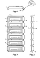
- the underside may be recessed so as to create compartments (5) open on the underside or concave. In this way, it is possible to stack interjoists (1) one above the other and thus reduce their size.
- each compartment (5) may be advantageous, as shown in Figure 3, to provide the upper face of each compartment (5) with a reinforcing rib (15).
- the interjoists (1) has at each end of its largest dimension arrangements (11, 12) of complementary shape, capable of cooperating with each other, to allow continuous splicing between two interjoists (1).
- This configuration allows for total formwork of a floor and thus avoids liquid concrete, during casting, to escape through gaps between two interjoists (1). It also prevents an operator from clogging at the different connections.
- interjoists (1) whose wall thickness is at most equal to ten millimeters.
- the interjoists (1) has, at its vertical recesses (7), zones (10) reinforced, able to support a false ceiling or pipes.
- Reinforced areas (14) may also be provided on the inclined side walls (13) of the compartments (5). These reinforced zones (10, 14), which are therefore thicker, may have the shape of pre-drilled bosses, making it possible to introduce fastening elements such as clips, to hold a cable or sheath in position, or threaded rods. to allow the installation of a false ceiling in particular.
- the section of the covers (16) has a shape of "Z" as shown in Figure 8. These caps can also be monobloc. In this case the lid (16) is cut in the direction of its length to adapt to the specific configurations at each site.
- the cover (16) may also be composed of two parts (19, 20) adapted to allow the realization of an adjustment according to the height of the interjoists (1) used.
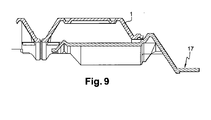
- the interjoists (1) may be provided with an end (17) to achieve the total formwork to the wall.
- Two abutments (17) are reported on each bay and can slide under a portion of the interjoists (1) end to fit perfectly the length of the spans.
- a relatively large portion of the abutment (17), at the level of the area of contact with the wall, is also able to be cut to allow its adaptation in the case where the wall is not perpendicular to the direction of the spans, and corollary, avoid any risk of introduction of concrete under the interjoists.
- the interjoists (1) is made of a composite material based on natural fibers and an adhesive.
- the selected natural fibers are part of the group of wood, flax and hemp.
Landscapes
- Engineering & Computer Science (AREA)
- Architecture (AREA)
- Electromagnetism (AREA)
- Civil Engineering (AREA)
- Structural Engineering (AREA)
- Physics & Mathematics (AREA)
- Forms Removed On Construction Sites Or Auxiliary Members Thereof (AREA)
- Cartons (AREA)
- Glass Compositions (AREA)
- Moulds For Moulding Plastics Or The Like (AREA)
- Inorganic Insulating Materials (AREA)
- Dental Preparations (AREA)
- Gasket Seals (AREA)
Claims (12)
- Dünnwandiger, geformter Füllkörper (1), welcher dazu bestimmt ist, zwischen zwei Trägern (2) mit Drahtgeflecht (3) angeordnet zu werden und auf der Befestigungsbasis (4) der genannten Träger (2) zu ruhen, um die Verschalung einer Druckplatte einer Decke zu bilden, wobei der genannte Füllkörper (1) eine Mehrzahl paarweise durch eine Rippe (6) voneinander getrennter Abschnitte (5) aufweist, wobei die Länge jeder Rippe (6) kleiner als die Länge der Abschnitte (5) ist, so daß sie sich nie auf der Befestigungsbasis (4) der Träger (2) abstützt, dadurch gekennzeichnet, daß jede der Rippen (6) mit mindestens einer Zone geringerer Festigkeit versehen ist, um die Teilbarkeit des Füllkörpers zwischen zwei aneinander grenzenden Abschnitten (5) ohne jegliches Werkzeug zu ermöglichen.
- Füllkörper nach Anspruch 1, dadurch gekennzeichnet, daß er mit einem Endstück (17) versehen ist, das dazu bestimmt ist, die Herstellung der vollständigen Verkleidung der Druckplatte der Decke sicherzustellen.
- Füllkörper nach Anspruch 2, dadurch gekennzeichnet, daß das Endstück (17) dazu geeignet ist, unterhalb eines Teils des Füllkörpers (1) zu gleiten.
- Füllkörper nach Anspruch 2, dadurch gekennzeichnet, daß das Endstück (17) an verschiedene Größen des Füllkörpers (1) anpaßbar ist.
- Füllkörper nach einem der Ansprüche 1 bis 4, dadurch gekennzeichnet, daß er im Bereich mindestens eines Endes jeder der Rippen (6) einen vertikalen Absatz (7) aufweist, der sich unterhalb der Oberseite (8) der Befestigungsbasis (4) jedes Trägers (2) erstreckt, dazu geeignet, mit einer der Seitenflächen (9) der genannten Befestigungsbasis (4) in Kontakt zu treten.
- Füllkörper nach Anspruch 5, dadurch gekennzeichnet, daß die vertikalen Absätze (7) verstärkte Zonen (10) aufweisen, die im wesentlichen parallel zur Oberseite (8) der Befestigungsbasis (4) der Träger (2) verlaufen und dazu bestimmt sind, die Befestigung einer Blinddecke oder von Rohrsträngen zu ermöglichen.
- Füllkörper nach einem der Ansprüche 1 bis 6, dadurch gekennzeichnet, daß die Abschnitte (5) auf einer Seite offen sind.
- Füllkörper nach einem der Ansprüche 1 bis 7, dadurch gekennzeichnet, daß er an jedem Ende seiner größten Dimension Anordnungen (11,12) mit komplementären Formen aufweist, um ein kontinuierliches Aneinanderfügen zweier aufeinanderfolgender Füllkörper (1) zu erlauben.
- Füllkörper nach einem der Ansprüche 1 bis 8, dadurch gekennzeichnet, daß seine Oberseite, die dazu bestimmt ist, mit dem Beton in Kontakt zu treten, Verstärkungsrippen (15) aufweist.
- Füllkörper nach einem der Ansprüche 1 bis 9, dadurch gekennzeichnet, daß er mit einem angebrachten Deckel (16) versehen ist, der die Rolle eines Anschlußstücks zu der Befestigungsbasis (4) des Trägers (2) spielt und sich in der gleichen Richtung wie der genannte Träger (2) erstreckt.
- Füllkörper nach einem der Ansprüche 1 bis 10, dadurch gekennzeichnet, daß er aus einem Verbundmaterial aus natürlichen Fasern oder Partikeln und einem Klebstoff hergestellt ist.
- Füllkörper nach Anspruch 11, dadurch gekennzeichnet, daß die natürlichen Fasern oder Partikel ausgewählt sind aus der Gruppe umfassend Holz, Lein und Hanf.
Applications Claiming Priority (2)
| Application Number | Priority Date | Filing Date | Title |
|---|---|---|---|
| FR0309455A FR2858343B1 (fr) | 2003-07-31 | 2003-07-31 | Entrevous emboitable moule |
| FR0309455 | 2003-07-31 |
Publications (2)
| Publication Number | Publication Date |
|---|---|
| EP1512803A1 EP1512803A1 (de) | 2005-03-09 |
| EP1512803B1 true EP1512803B1 (de) | 2006-12-06 |
Family
ID=34043706
Family Applications (1)
| Application Number | Title | Priority Date | Filing Date |
|---|---|---|---|
| EP04103549A Expired - Lifetime EP1512803B1 (de) | 2003-07-31 | 2004-07-23 | Einsteckbarer Formfüllkörper |
Country Status (5)
| Country | Link |
|---|---|
| EP (1) | EP1512803B1 (de) |
| AT (1) | ATE347639T1 (de) |
| DE (1) | DE602004003531T2 (de) |
| ES (1) | ES2276227T3 (de) |
| FR (1) | FR2858343B1 (de) |
Families Citing this family (14)
| Publication number | Priority date | Publication date | Assignee | Title |
|---|---|---|---|---|
| ITPD20040087A1 (it) * | 2004-04-01 | 2004-07-01 | Assounisol Srl | Elemento modulare prefabbricato per la realizzazione degli alleggerimenti in solai a travetti tralicciati o lastre di tipo predalle |
| EP1736607B1 (de) * | 2005-06-23 | 2012-01-11 | Plasticform S.R.L. | Füll- und Dämmelement und Bausystem mit solch einem Element |
| FR2916215B1 (fr) * | 2007-05-14 | 2009-07-10 | Kp1 Soc Par Actions Simplifiee | Entrevous en matiere plastique injectee |
| FR2916212B1 (fr) * | 2007-05-15 | 2013-12-13 | Rector Lesage | Dispositif d'isolation pour plancher a poutrelles et plancher obtenu |
| FR2919317B1 (fr) * | 2007-07-26 | 2012-08-24 | Imerys Tc | Entrevous leger a paroi mince. |
| ITPD20070347A1 (it) * | 2007-10-22 | 2009-04-23 | Geoplast Spa | Casseratura modulare riutilizzabile per la realizzazione di solai nervati in c. a. |
| FR2944816B1 (fr) * | 2009-04-28 | 2011-06-03 | Jean Louis Gaziello | Entrevous pour entraxe variable et structure de coffrage |
| FR2948706B1 (fr) * | 2009-07-31 | 2016-12-09 | Kp1 | Entrevous modulable |
| FR2956421B1 (fr) * | 2010-02-12 | 2012-08-10 | Rector Lesage | Entrevous pour plancher a poutrelles |
| FR2961226A1 (fr) * | 2010-06-15 | 2011-12-16 | Applic Composants Guiraud Freres Soc Et | Perfectionnement aux hourdis moules |
| CN103452219A (zh) * | 2013-09-16 | 2013-12-18 | 南京工业大学 | 一种蜂窝钢暗梁组合楼盖 |
| CN103572875A (zh) * | 2013-11-05 | 2014-02-12 | 南京工业大学 | 一种钢箱暗梁组合楼盖 |
| CN103993691B (zh) * | 2014-04-27 | 2016-10-05 | 浙江绿筑建筑系统集成有限公司 | 一种集成式楼面模块及其拼装方法 |
| FR3099503B1 (fr) | 2019-08-02 | 2023-01-06 | Lesage Dev | Procédé de mise en œuvre d’entrevous de coffrage pour plancher à poutrelles et entrevous de coffrage correspondant |
Family Cites Families (4)
| Publication number | Priority date | Publication date | Assignee | Title |
|---|---|---|---|---|
| GB1129892A (en) * | 1965-11-08 | 1968-10-09 | Atlas Stone Company Ltd | Improvements relating to the construction of floors or roofs |
| DE2250295A1 (de) * | 1971-10-19 | 1973-04-26 | Emballages De Quevilly Petit Q | Verlorene schalung in gewoelbter form |
| GB2077792B (en) | 1980-03-22 | 1983-06-08 | Tinsley Building Prod Ltd | Casting reinforced concrete floors |
| FR2786514B1 (fr) | 1998-11-26 | 2001-01-19 | Saret France | Entrevous a paroi mince |
-
2003
- 2003-07-31 FR FR0309455A patent/FR2858343B1/fr not_active Expired - Lifetime
-
2004
- 2004-07-23 ES ES04103549T patent/ES2276227T3/es not_active Expired - Lifetime
- 2004-07-23 DE DE602004003531T patent/DE602004003531T2/de not_active Expired - Fee Related
- 2004-07-23 AT AT04103549T patent/ATE347639T1/de not_active IP Right Cessation
- 2004-07-23 EP EP04103549A patent/EP1512803B1/de not_active Expired - Lifetime
Also Published As
| Publication number | Publication date |
|---|---|
| ATE347639T1 (de) | 2006-12-15 |
| FR2858343B1 (fr) | 2007-04-20 |
| DE602004003531T2 (de) | 2007-04-05 |
| FR2858343A1 (fr) | 2005-02-04 |
| DE602004003531D1 (de) | 2007-01-18 |
| ES2276227T3 (es) | 2007-06-16 |
| EP1512803A1 (de) | 2005-03-09 |
Similar Documents
| Publication | Publication Date | Title |
|---|---|---|
| EP1512803B1 (de) | Einsteckbarer Formfüllkörper | |
| EP2022150B1 (de) | Trennungs- und/oder verstärkungsvorrichtung für einen drahtkabelkanal | |
| EP1841929B1 (de) | Anordnung von elementen zur herstellung einer tafel | |
| EP2791441B1 (de) | Wärmedämmsystem und entsprechendes montageverfahren | |
| EP2857584B1 (de) | Modulares System für einen Schienenfahrweg auf Plattenelementen | |
| FR2754285A1 (fr) | Element de coffrage isolant pour mur en beton | |
| WO2017017357A1 (fr) | Procede de fabrication d'un element de paroi d'un reservoir etanche et thermiquement isolant | |
| EP3483339B1 (de) | Vereinfachte reparierungsmethode für betonierfugenausbildung einer bodenplatte | |
| EP2391775B1 (de) | Bauelement und solche elemente verwendende stützwand | |
| EP3181775B1 (de) | Gründach | |
| WO2016005679A1 (fr) | Poutrelle pour la realisation d'un plancher | |
| FR2941725A1 (fr) | Element d'isolation thermique pour bloc prefabrique et bloc de construction ainsi obtenu. | |
| FR2913993A1 (fr) | Entrevous en matrice minerale, dispositif de plancher a entrevous et son procede de realisation | |
| FR3017147A1 (fr) | Caisson pour boite d'attente et boite d'attente munie d'un tel caisson | |
| FR2807080A1 (fr) | Coffrage isolant aplatissable pour la realisation d'un mur en beton | |
| FR2962066A1 (fr) | Procede de fabrication d'un element structurel en beton et element structurel prefabrique en beton. | |
| EP1921227A1 (de) | Modulstruktur zur Herstellung von Wänden, die im Einsatz horizontalen Schubkräften ausgesetzt sind, insbesondere Beckenbegrenzungswände | |
| EP2216442B1 (de) | Vorrichtung zur Ausstattung einer Dehnungsfuge, insbesondere einer Dehnungsfuge zwischen Betonplatten | |
| FR2889552A1 (fr) | Element de coffrage perdu et module pour la realisation d'un tel element. | |
| EP2868808A1 (de) | Herstellungsverfahren eines Belüftungshohlraums, Baukomplex, der die Umsetzung dieses Verfahrens ermöglicht, und spezielles Befestigungsorgan | |
| FR2922912A1 (fr) | Dispositif d'interruption thermique pour plancher en beton | |
| FR2795110A1 (fr) | Coffrage isolant pour la realisation d'un mur en beton | |
| FR2737515A1 (fr) | Dispositif de maintien et de coffrage pour reseaux de distribution souterrains, en particulier electriques, telephoniques, cables, ou autres | |
| FR2872187A1 (fr) | Entrevous en matiere plastique alveolaire pour poutrelles en acier plie | |
| EP2871298A1 (de) | Modulsystem zum Bau von Gebäuden, das mit Platinen befestigte Module umfasst |
Legal Events
| Date | Code | Title | Description |
|---|---|---|---|
| PUAI | Public reference made under article 153(3) epc to a published international application that has entered the european phase |
Free format text: ORIGINAL CODE: 0009012 |
|
| AK | Designated contracting states |
Kind code of ref document: A1 Designated state(s): AT BE BG CH CY CZ DE DK EE ES FI FR GB GR HU IE IT LI LU MC NL PL PT RO SE SI SK TR |
|
| AX | Request for extension of the european patent |
Extension state: AL HR LT LV MK |
|
| 17P | Request for examination filed |
Effective date: 20050510 |
|
| AKX | Designation fees paid |
Designated state(s): AT BE BG CH CY CZ DE DK EE ES FI FR GB GR HU IE IT LI LU MC NL PL PT RO SE SI SK TR |
|
| GRAP | Despatch of communication of intention to grant a patent |
Free format text: ORIGINAL CODE: EPIDOSNIGR1 |
|
| GRAS | Grant fee paid |
Free format text: ORIGINAL CODE: EPIDOSNIGR3 |
|
| GRAA | (expected) grant |
Free format text: ORIGINAL CODE: 0009210 |
|
| AK | Designated contracting states |
Kind code of ref document: B1 Designated state(s): AT BE BG CH CY CZ DE DK EE ES FI FR GB GR HU IE IT LI LU MC NL PL PT RO SE SI SK TR |
|
| PG25 | Lapsed in a contracting state [announced via postgrant information from national office to epo] |
Ref country code: NL Free format text: LAPSE BECAUSE OF FAILURE TO SUBMIT A TRANSLATION OF THE DESCRIPTION OR TO PAY THE FEE WITHIN THE PRESCRIBED TIME-LIMIT Effective date: 20061206 Ref country code: DK Free format text: LAPSE BECAUSE OF FAILURE TO SUBMIT A TRANSLATION OF THE DESCRIPTION OR TO PAY THE FEE WITHIN THE PRESCRIBED TIME-LIMIT Effective date: 20061206 Ref country code: SK Free format text: LAPSE BECAUSE OF FAILURE TO SUBMIT A TRANSLATION OF THE DESCRIPTION OR TO PAY THE FEE WITHIN THE PRESCRIBED TIME-LIMIT Effective date: 20061206 Ref country code: SI Free format text: LAPSE BECAUSE OF FAILURE TO SUBMIT A TRANSLATION OF THE DESCRIPTION OR TO PAY THE FEE WITHIN THE PRESCRIBED TIME-LIMIT Effective date: 20061206 Ref country code: FI Free format text: LAPSE BECAUSE OF FAILURE TO SUBMIT A TRANSLATION OF THE DESCRIPTION OR TO PAY THE FEE WITHIN THE PRESCRIBED TIME-LIMIT Effective date: 20061206 Ref country code: PL Free format text: LAPSE BECAUSE OF FAILURE TO SUBMIT A TRANSLATION OF THE DESCRIPTION OR TO PAY THE FEE WITHIN THE PRESCRIBED TIME-LIMIT Effective date: 20061206 Ref country code: CZ Free format text: LAPSE BECAUSE OF FAILURE TO SUBMIT A TRANSLATION OF THE DESCRIPTION OR TO PAY THE FEE WITHIN THE PRESCRIBED TIME-LIMIT Effective date: 20061206 Ref country code: AT Free format text: LAPSE BECAUSE OF FAILURE TO SUBMIT A TRANSLATION OF THE DESCRIPTION OR TO PAY THE FEE WITHIN THE PRESCRIBED TIME-LIMIT Effective date: 20061206 Ref country code: IE Free format text: LAPSE BECAUSE OF FAILURE TO SUBMIT A TRANSLATION OF THE DESCRIPTION OR TO PAY THE FEE WITHIN THE PRESCRIBED TIME-LIMIT Effective date: 20061206 |
|
| REG | Reference to a national code |
Ref country code: GB Ref legal event code: FG4D Free format text: NOT ENGLISH |
|
| REG | Reference to a national code |
Ref country code: CH Ref legal event code: EP |
|
| REG | Reference to a national code |
Ref country code: IE Ref legal event code: FG4D Free format text: LANGUAGE OF EP DOCUMENT: FRENCH |
|
| REF | Corresponds to: |
Ref document number: 602004003531 Country of ref document: DE Date of ref document: 20070118 Kind code of ref document: P |
|
| REG | Reference to a national code |
Ref country code: RO Ref legal event code: EPE |
|
| PG25 | Lapsed in a contracting state [announced via postgrant information from national office to epo] |
Ref country code: BG Free format text: LAPSE BECAUSE OF FAILURE TO SUBMIT A TRANSLATION OF THE DESCRIPTION OR TO PAY THE FEE WITHIN THE PRESCRIBED TIME-LIMIT Effective date: 20070306 Ref country code: SE Free format text: LAPSE BECAUSE OF FAILURE TO SUBMIT A TRANSLATION OF THE DESCRIPTION OR TO PAY THE FEE WITHIN THE PRESCRIBED TIME-LIMIT Effective date: 20070306 |
|
| PG25 | Lapsed in a contracting state [announced via postgrant information from national office to epo] |
Ref country code: PT Free format text: LAPSE BECAUSE OF FAILURE TO SUBMIT A TRANSLATION OF THE DESCRIPTION OR TO PAY THE FEE WITHIN THE PRESCRIBED TIME-LIMIT Effective date: 20070507 |
|
| NLV1 | Nl: lapsed or annulled due to failure to fulfill the requirements of art. 29p and 29m of the patents act | ||
| REG | Reference to a national code |
Ref country code: ES Ref legal event code: FG2A Ref document number: 2276227 Country of ref document: ES Kind code of ref document: T3 |
|
| GBV | Gb: ep patent (uk) treated as always having been void in accordance with gb section 77(7)/1977 [no translation filed] |
Effective date: 20061206 |
|
| PLBE | No opposition filed within time limit |
Free format text: ORIGINAL CODE: 0009261 |
|
| STAA | Information on the status of an ep patent application or granted ep patent |
Free format text: STATUS: NO OPPOSITION FILED WITHIN TIME LIMIT |
|
| 26N | No opposition filed |
Effective date: 20070907 |
|
| PG25 | Lapsed in a contracting state [announced via postgrant information from national office to epo] |
Ref country code: GB Free format text: LAPSE BECAUSE OF FAILURE TO SUBMIT A TRANSLATION OF THE DESCRIPTION OR TO PAY THE FEE WITHIN THE PRESCRIBED TIME-LIMIT Effective date: 20061206 |
|
| PG25 | Lapsed in a contracting state [announced via postgrant information from national office to epo] |
Ref country code: GR Free format text: LAPSE BECAUSE OF FAILURE TO SUBMIT A TRANSLATION OF THE DESCRIPTION OR TO PAY THE FEE WITHIN THE PRESCRIBED TIME-LIMIT Effective date: 20070307 |
|
| PGFP | Annual fee paid to national office [announced via postgrant information from national office to epo] |
Ref country code: MC Payment date: 20080618 Year of fee payment: 5 |
|
| PGFP | Annual fee paid to national office [announced via postgrant information from national office to epo] |
Ref country code: CH Payment date: 20080715 Year of fee payment: 5 Ref country code: DE Payment date: 20080715 Year of fee payment: 5 Ref country code: ES Payment date: 20080718 Year of fee payment: 5 Ref country code: LU Payment date: 20080728 Year of fee payment: 5 |
|
| PGFP | Annual fee paid to national office [announced via postgrant information from national office to epo] |
Ref country code: IT Payment date: 20080726 Year of fee payment: 5 Ref country code: RO Payment date: 20080714 Year of fee payment: 5 |
|
| PG25 | Lapsed in a contracting state [announced via postgrant information from national office to epo] |
Ref country code: EE Free format text: LAPSE BECAUSE OF FAILURE TO SUBMIT A TRANSLATION OF THE DESCRIPTION OR TO PAY THE FEE WITHIN THE PRESCRIBED TIME-LIMIT Effective date: 20061206 |
|
| PGFP | Annual fee paid to national office [announced via postgrant information from national office to epo] |
Ref country code: BE Payment date: 20080814 Year of fee payment: 5 |
|
| PG25 | Lapsed in a contracting state [announced via postgrant information from national office to epo] |
Ref country code: CY Free format text: LAPSE BECAUSE OF FAILURE TO SUBMIT A TRANSLATION OF THE DESCRIPTION OR TO PAY THE FEE WITHIN THE PRESCRIBED TIME-LIMIT Effective date: 20061206 |
|
| PG25 | Lapsed in a contracting state [announced via postgrant information from national office to epo] |
Ref country code: HU Free format text: LAPSE BECAUSE OF FAILURE TO SUBMIT A TRANSLATION OF THE DESCRIPTION OR TO PAY THE FEE WITHIN THE PRESCRIBED TIME-LIMIT Effective date: 20070607 Ref country code: TR Free format text: LAPSE BECAUSE OF FAILURE TO SUBMIT A TRANSLATION OF THE DESCRIPTION OR TO PAY THE FEE WITHIN THE PRESCRIBED TIME-LIMIT Effective date: 20061206 |
|
| BERE | Be: lapsed |
Owner name: FIMUREX Effective date: 20090731 |
|
| PG25 | Lapsed in a contracting state [announced via postgrant information from national office to epo] |
Ref country code: MC Free format text: LAPSE BECAUSE OF NON-PAYMENT OF DUE FEES Effective date: 20090731 |
|
| REG | Reference to a national code |
Ref country code: CH Ref legal event code: PL |
|
| PG25 | Lapsed in a contracting state [announced via postgrant information from national office to epo] |
Ref country code: RO Free format text: LAPSE BECAUSE OF NON-PAYMENT OF DUE FEES Effective date: 20090723 Ref country code: LI Free format text: LAPSE BECAUSE OF NON-PAYMENT OF DUE FEES Effective date: 20090731 Ref country code: CH Free format text: LAPSE BECAUSE OF NON-PAYMENT OF DUE FEES Effective date: 20090731 |
|
| PG25 | Lapsed in a contracting state [announced via postgrant information from national office to epo] |
Ref country code: BE Free format text: LAPSE BECAUSE OF NON-PAYMENT OF DUE FEES Effective date: 20090731 Ref country code: DE Free format text: LAPSE BECAUSE OF NON-PAYMENT OF DUE FEES Effective date: 20100202 |
|
| REG | Reference to a national code |
Ref country code: ES Ref legal event code: FD2A Effective date: 20090724 |
|
| PG25 | Lapsed in a contracting state [announced via postgrant information from national office to epo] |
Ref country code: ES Free format text: LAPSE BECAUSE OF NON-PAYMENT OF DUE FEES Effective date: 20090724 |
|
| PG25 | Lapsed in a contracting state [announced via postgrant information from national office to epo] |
Ref country code: IT Free format text: LAPSE BECAUSE OF NON-PAYMENT OF DUE FEES Effective date: 20090723 |
|
| PG25 | Lapsed in a contracting state [announced via postgrant information from national office to epo] |
Ref country code: LU Free format text: LAPSE BECAUSE OF NON-PAYMENT OF DUE FEES Effective date: 20090723 |
|
| REG | Reference to a national code |
Ref country code: FR Ref legal event code: PLFP Year of fee payment: 13 |
|
| REG | Reference to a national code |
Ref country code: FR Ref legal event code: PLFP Year of fee payment: 14 |
|
| REG | Reference to a national code |
Ref country code: FR Ref legal event code: PLFP Year of fee payment: 15 |
|
| PGFP | Annual fee paid to national office [announced via postgrant information from national office to epo] |
Ref country code: FR Payment date: 20230728 Year of fee payment: 20 |