Technical Field
The present invention relates to an elevator apparatus, and
more particularly to an elevator apparatus for use in the machinery
room arranged at the top of the elevator shaft.
Background Art
Figure 5 is a schematic view illustrating the interior of
an elevator apparatus 200 according to the prior art.
As shown in Figure 5, the elevator apparatus 200 is provided
with an elevator shaft 2. The top part of the shaft 2 is partitioned
by a machinery room floor 4, and there is arranged a machinery
room 6.
From the shaft 2 are hung a cage 8 and a balance weight 10,
and the cage 8 and the balance weight 10 move up and down in the
shaft 2.
The machinery room 6 is also provided with a hoisting machine
12, to which is connected a control device 14. The machinery
room 6 is provided with a door 16 for entrance into and exit from
the machinery room 6.
Round the hoisting machine 12 is wound a rope 18, one end
of which hangs from the machinery room 6 into the shaft 2 and
is connected to the cage 8 to suspend the cage 8 in the shaft
2. The other end hangs from the machinery room 6 into the shaft
2 and is connected to the balance weight 10 to suspend the balance
weight 10 in the shaft 2.
Figure 6 shows a top view of the machinery room 6 of the
elevator apparatus 200 and Figure 7, a sectional view of the
machinery room 6 along A-A' in Figure 6.
As shown in Figure 6 and Figure 7, the machinery room floor
4 comprises structural beams 62, a machinery room floor plate
44 and machinery bases 66.
The structural beams 62 are fixed to walls of the shaft 2
at a prescribed height in the shaft 2. The machinery room floor
plate 44 is arranged over the structural beams 62. The structural
beams 62 support two ends of the machinery room floor plate 44,
namely the right and left ends as viewed in Figure 6 and Figure
7. The machinery room floor plate 44 is also provided with rope
passages 68 and 70.
Above the machinery room floor plate 44 are arranged two
parallel machinery bases 66 in a direction normal to the structural
beams 62. The machinery bases 66 are pillars of 300 mm to 500
mm in height. On the machinery bases 66 is installed the hoisting
machine 12.
Sufficient strength should be secured for the machinery bases
66 to support the hoisting machine 12 which moves up and down
the cage 8 and the balance weight 10 suspended from it. Therefore,
the machinery bases 66 need some height.
As described above, in the machinery room 6, there are
provided the machinery bases 66 of 300 to 500 mm in height, and
these hoisting machine 12 and control device 14 are further
installed among other things. However, when an elevator
apparatus is to be installed in a building or elsewhere, often
the space it occupies is required to be minimized, and this
requirement necessitates a reduction in the dimensions of the
machinery room 6 to be arranged at the top of the elevator,
inevitably resulting in more or less restrictions on the size
of the machinery room 6.
When the hoisting machine 12, the control device 14 or any
other item of equipment is to be inspected or repaired in this
limited space of the machinery room, sufficient footholds cannot
be secured on account of projections including the machinery bases
66, and the maintenance personnel would have to work in an unnatural
posture, such as riding on the machinery bases 66 or keeping away
from projections including the machinery bases 66, the hoisting
machine 12 and the control device 14. This makes difficult smooth
accomplishment of the maintenance work, which would therefore
take a longer time and keep the elevator suspended from operation
for a long period during a safety check or the like.
The requirement for a smaller machinery room 6 has become
even more stringent, and now it is of ten demanded that the machinery
room 6 be equal in width to the shaft 2, i.e. the sectional area
of the machinery room 6 in the horizontal direction be equal to
that of the shaft 2 as shown in Figures 5 through 7. If this
requirement is met, in particular, opening the door 16 of the
machinery room 6, the maintenance personnel will find the
machinery bases 66 installed just ahead of them, which means a
large level gap just inside the entrance. Furthermore, as the
machinery bases 66 would span the full width of the room, there
would be no space to install the control device 14 elsewhere than
on the machinery bases 66. However, since the control device
14 is relatively tall, arranging it on the machinery bases 66
would necessitate some overhead clearance in the machinery room
6.
Disclosure of the Invention
Therefore, with an eye to solving the problems noted above,
the present invention is to intended to propose an improved
elevator apparatus which enables a machinery room, limited in
dimensions by structural constraints of the elevator, to be used
without inconvenient dimensional restriction and to be reduced
in projections inside.
To achieve this object, an elevator apparatus according to
the invention comprises a shaft in which the cage of the elevator
moves up and down, a machinery room, a machinery room floor to
serve as a partitioning between the machinery room and the shaft,
and a hoisting machine installed in the machinery room to move
up and down the cage of the elevator, wherein the machinery room
floor includes supporting parts fixed in a prescribed position
in the shaft, and machinery bases supported by the supporting
parts to accommodate the installation of the hoisting machine,
wherein each of the machinery bases has a machinery base
installation part to accommodate the installation of the hoisting
machine, and machinery base supporting parts supported by the
supporting parts, wherein the machinery base installation part
is formed thicker than the machinery base supporting parts.
In this way, it is possible to reduce the overall thickness
of the machinery room floor while securing the strength of the
machinery bases, accordingly to make the whole structure thinner
and expand the available space in the machinery room, thereby
facilitating maintenance work in the machinery room.
In an elevator apparatus according to the invention, the
machinery room floor may be further provided with a machinery
room floor plate supported by the supporting parts and between
the supporting parts and the machinery base supporting parts,
and the machinery base installation part be fitted into the
machinery room floor plate.
In an elevator apparatus according to the invention, the
machinery room floor plate has an opening in the middle part,
and the machinery base installation part is engaged with and fitted
into the opening.
In an elevator apparatus according to the present invention,
the machinery room floor is further provided with a floor surface
plate supported by the machinery bases, covering the machinery
room floor all over.
In an elevator apparatus according to the present invention,
it is further provided with a control device for controlling the
rotation of the hoisting machine.
In an elevator apparatus according to the present invention,
the control device is partly fitted into the machinery room floor.
In an elevator apparatus according to the present invention,
it is further provided with a control device for controlling the
rotation of the hoisting machine control device, wherein the
control device includes an L-shaped portion whose two faces cross
each other substantially normally, and one of the two faces is
fitted into the floor surface plate and supported by the supporting
parts.
In an elevator apparatus according to present invention,
the machinery room is formed by partitioning the upper part of
the shaft and the sectional area of the shaft in the horizontal
direction is equal to the sectional area of the machinery room
in the horizontal direction.
Brief Descriptions of Drawings
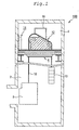
Figure 1 shows a schematic view of an elevator apparatus
to describe one of the best modes for carrying out the invention.
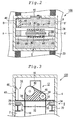
Figure 2 shows a top view of the machinery room of the elevator
apparatus to describe one of the best modes for carrying out the
invention.
Figure 3 shows a sectional view of the machinery room of
the elevator apparatus to describe one of the best modes for
carrying out the invention.
Figure 4 shows a sectional view of the machinery room of
the elevator apparatus to describe one of the best modes for
carrying out the invention.
Figure 5 shows a schematic view of an conventional elevator
apparatus.
Figure 6 shows a top view of the machinery room of the
conventional elevator apparatus.
Figure 7 shows a sectional view of the machinery room of
the conventional elevator apparatus.
Best Modes for Carrying Out the Invention
Modes for implementing the present invention will be
described below with reference to the drawings. In these drawings,
the same or equivalent constituent parts are denoted by
respectively the same reference signs, and their description is
either simplified or omitted.
Figure 1 shows a front view of an elevator apparatus 100
to describe one of the best modes for carrying out the invention,
with the front wall of the elevator apparatus 100 removed to reveal
the interior. As shown in Figure 1, the elevator apparatus 100
is provided with a shaft 2. The top part of the shaft 2 is
partitioned by a machinery room floor 4, and there is arranged
a machinery room 6.
A cage 8 and a balance weight 10 are suspended into the shaft
2.
The machinery room 6 is provided with a hoisting machine
12, to which is connected a control device 14. The machinery
room 6 is provided with a machinery room door 16 for entrance
into and exit from the machinery room 6.
Round the hoisting machine 12 is wound a rope 18, one end
of which hangs from the machinery room 6 into the shaft 2 and
is connected to the cage 8 to suspend the cage 8 in the shaft
2. The other end hangs from the machinery room 6 into the shaft
2 and is connected to the balance weight 10 to suspend the balance
weight 10 in the shaft 2.
In the elevator apparatus 100 configured in this way, the
revolving speed of the hoisting machine 12 is set by the control
device 14, and the rotation and stopping of the hoisting machine
12 during the operation of the elevator are also controlled by
the control device 14.
When the control device 14 starts the rotation of the hoisting
machine 12, the rope 18 wound round the hoisting machine 12 begins
moving according to the direction of rotation, and the cage 8
and the balance weight 10 are thereby caused to move vertically
within the shaft 2 in abalancedway inmutuallyreverse directions.
Figure 2 shows a top view of the machinery room 6 of the
elevator apparatus 100, including a partial perspective view.
Figure 3 shows a sectional view of the machinery room 6 along
the A-A' plane in Figure 2, and Figure 4, a sectional view along
the B-B' plane.
The machinery room floor 4 comprises structural beams 20,
a machinery room floor plate 22, machinery bases 24 and an upper
floor plate 26.
The structural beams 20, I-shaped as viewed from front as
shown in Figure 3 and Figure 4, are fixed at a prescribed height
in the shaft 2, protruding from the two side walls, right and
left, of the shaft 2. The machinery room floor plate 22 is a
board having a square opening 28 in the central part. The
machinery room floor plate 22 is arranged over the structural
beams 20, and supported by the structural beams 20 at its two
ends, namely the right and left ends as viewed in Figure 2 through
Figure 4.
The machinery bases 24 consist of two beams. Each beam is
a basically I-section bar like either machinery bases in the prior
art configuration but cut at the right and left ends to be made
thinner, and consists of machinery base ends 30 cut to be thinner
and a machinery base middle part 32 left in its original thickness.
The machinery base middle part 32 is 300 mm to 500 mm thick in
its thickest portion. The machinery base ends 30 are so installed
over the machinery room floor plate 22 that the lengthwise
direction of each beam be normal to the structural beams 20. The
machinery base middle part 32 is connected to and supported by
the machinery base ends 30, and so arranged as to look positioned
at the center of the machinery room floor 4 as viewed from front.
The machinery base middle part 32 is fitted into the opening 28
bored in the machinery room floor plate 22 and protrudes below
the surface of the machinery room floor plate 22.
All over the machinery bases 24 is laid the upper floor plate
26, though the upper floor plate 26 is not shown in Figure 2 because
this drawing shows the upper face in a state in which the upper
floor plate 26 is removed. The upper floor plate 26 is a flat
board covering the floor of the machinery room 6 all over. Rope
passing holes 34 and 36 are bored in the upper floor plate 26.
Over the machinery room floor 4 configured as described above
is installed the hoisting machine 12. The hoisting machine 12
is provided with supporting boards 40, and a large pulley 42 and
a small pulley 44, both rotatably fitted to the supporting boards
40. By rotating the large and small pulleys 42 and 44 of the
hoisting machine 12, the rope 18 threaded round the large and
small pulleys 42 and 44 is moved right or left, the cage 8 and
the balance weight 10 can be raised or lowered by the rope motion.
The control device 14 comprises a control board 46 and a
control board fixture 48. The control board 46 is a small and
thin control board, and the control board fixture 48 is a thin
L-shaped item whose two faces cross each other at 90 degrees.
The control board 46 is fixed by the control board fixture 48.
As shown in Figure 4, the bottom portion of the control board
fixture 48 is embedded underneath the upper floor plate 26. and
installed over the machinery room floor plate 22. A cable for
transmitting rotation and stop signals from the control device
14 to the hoisting machine 12 is also laid underneath the upper
floorplate 26. Thus, though the upper floorplate 26 is installed
over the machinery bases 24, there is void space between the upper
floor plate 26 and the machinery room floor plate 22 where the
machinery bases 24 is not arranged, because the machinery bases
24 are two beams disposed over the machinery room floor plate
22. By utilizing this void space, the control device 14 is
installed, with the lower portion of the control board fixture
48 of the control device 14 and a cable 50 connected to the lower
portion of the control board 46 being embedded underneath the
upper floor plate 26.
As hitherto described, in this mode for carrying out the
invention, the machinery bases 24 are composed of beams having
a shape formed by thinning both end parts of conventional beams.
Thus, the machinery base middle part 32 of the machinery bases
24 supporting the hoisting machine 12 is formed somewhat thicker
than the machinery base ends 30. This thicker machinery base
middle part 32 is fitted into the opening 30 of the machinery
room floor plate 22. Accordingly, the machinery room floor 4
can be formed generally thin to enable a larger available space
to be secured in the machinery room 6. Therefore, safety check
and repair operations in the machinery room 6 can be accomplished
more efficiently to reduce the length of time taken for maintenance,
resulting in improved elevator servicing.
In this arrangement of the machinery bases 24, the machinery
base middle part 32 on which the hoisting machine 12 is installed
is subject to the greatest force due to the up and down movements
of the cage 8 and the balance weight 10. Therefore, the greater
thickness of the part on which the hoisting machine or some other
load are installed makes it possible to provide sufficient
strength to the machinery bases 24 to support the hoisting machine
12.
Further in this mode for carrying out the invention, the
upper floor plate 26 prevents the machinery bases 24 from
protruding out of the surface of the machinery room floor 4.
Therefore, the machinery room floor 4 is flat where there is no
equipment installed, such as the hoisting machine 12 or the control
device 14. This makes possible suppressing the level gap within
the machinery room 6 when entering or leaving the machinery room
through the door 16 and ensuring adequate footholds for
maintenance personnel working in the machinery room 6 for safety
check or repair of the hoisting machine 12 or the control device
14, enabling the personnel to accomplish the work more efficiently
and reduce the length of time taken for maintenance, resulting
in improved elevator servicing.
Further in this mode for carrying out the invention, the
lower portion of the control board fixture 42 of the control device
14 and the cable 50 are embedded underneath the upper floor plate
26 and installed by utilizing the void space between the upper
floor plate 26 and the machinery room floor plate 22. Therefore,
as the relatively tall control device 14 can be arranged in a
low position away from the machinery bases 24, the control device
14 can be prevented from adding to the height of the machinery
room 6.
In addition, one face of the L-shaped control board fixture
48 is embedded in the machinery room floor 4, and the thin control
board 46 is fixed to this control board fixture 48. Therefore,
the control device 14 can be installed in a stable state without
having to reduce its overall thickness and sacrifice part of its
width for parts needed for its installation.
Although this mode for carrying out the invention has been
described with reference to a configuration in which the control
device 14 is arranged within the machinery room 6, the invention
is not limited to this configuration, but the control device 14
may as well be provided outside the elevator apparatus. Even
if the control device is installed within the machinery room 6,
the shape of the control device need not be shaped as described
above, but may have some other shape. Furthermore, the control
device need not be fitted into the machinery room floor 4, but
may instead be installed on the top face of the machinery room
floor 4 as according to the prior art.
Further in this mode for carrying out the invention, the
machinery room floor plate 22 has the square opening 30, and by
fitting the machinery base middle part 42 into this opening, the
machinery bases 24 are fitted into the machinery room floor plate
22. However, the opening need not be square, but two rectangular
openings, longer laterally, matching the shape of the machinery
base middle part 42 may as well be arranged in parallel. In this
case, however, additional rope passing holes would be needed.
Also, the method of fitting the machinery bases 24 into the
machinery room floor plate 22 is not limited to what was described
above.
Further in this mode for carrying out the invention, each
of the machinery bases 24 is provided with the thicker machinery
room middle part 32 to be arranged in the central part of the
machinery room 6, and here is arranged the hoisting machine 12.
However, the shape of the machinery bases 24 is not limited to
this, but it is only required that the part where the hoisting
machine 12 is to be installed is formed thick enough.
Further with respect to this mode for carrying out the
invention, while a case in which the width of the machinery room
6 is equal to that of the shaft 2, i.e. the sectional area of
the machinery room 6 in the horizontal direction is equal to that
of the shaft 2, was described, the invention is not limited to
this case, but the width of the machinery room 6 may be greater
than that of the shaft 2 if an even greater available space in
the machinery room 6 is required.
In addition, the mechanism for moving up and down the elevator
apparatus and the shape, structure and other features of the
hoisting machine 12, the structural beams 20 and other items are
not necessarily limited to what were described with reference
to this mode for carrying out the invention, but other shape,
structure and so forth can be usedwithin the scope of the invention.
Incidentally, in the present invention, the supporting parts
are the parts supporting the machinery room floor, and the
structural beams 20 constitute the supporting parts in this mode
for carrying out the invention for instance. The machinery base
installation part is what is formed thicker than the rest of the
machinery bases to bear the installation of the hoisting machine,
and the machinery room middle part 32 constitutes this part in
this mode for carrying out the invention for instance. The
machinery base supporting parts are what are supported by the
aforementioned supporting parts, and the machinery room ends 30
constitute these parts in this mode for carrying out the invention
for instance.
Industrial Applicability
As hitherto described, according to the present invention,
the parts of the machinery bases where the hoisting machine is
to be installed are formed thicker than elsewhere, and these parts
are fitted into the machinery room floor plate. Accordingly,
the available space in the machinery room can be expanded by
thinning the overall thickness of the machinery room floor while
maintaining the necessary strength of the parts of the machinery
bases where the hoistingmachine and other items are to be installed.
Therefore, space saving in the machinery room can be achieved.
Work can be done efficiently even in a small machinery room, thereby
making possible improved elevator servicing.
Where a surface floor plate is to be laid over the top face
of the machinery bases in a configuration according to the
invention, projections from the machinery room floor can be made
fewer. Therefore, even more footholds can be secured to enhance
the efficiency of work in the machinery room and thereby reduce
the length of time taken for maintenance work.
Further in a configuration according to the invention where
the control device is fitted into the machinery room floor, the
overall height of the machinery room can be prevented from being
increased by the arrangement of a taller control device.
Therefore, space saving in the machinery room can be achieved.
Also, as part of the control device is so structured as to be
fitted in, even a thinner control device can be stably installed.