EP1512636A2 - Materialbahn von vorgeöffneten medizinischen Beuteln - Google Patents
Materialbahn von vorgeöffneten medizinischen Beuteln Download PDFInfo
- Publication number
- EP1512636A2 EP1512636A2 EP04254979A EP04254979A EP1512636A2 EP 1512636 A2 EP1512636 A2 EP 1512636A2 EP 04254979 A EP04254979 A EP 04254979A EP 04254979 A EP04254979 A EP 04254979A EP 1512636 A2 EP1512636 A2 EP 1512636A2
- Authority
- EP
- European Patent Office
- Prior art keywords
- die
- base material
- continuous web
- cut
- plastic film
- Prior art date
- Legal status (The legal status is an assumption and is not a legal conclusion. Google has not performed a legal analysis and makes no representation as to the accuracy of the status listed.)
- Withdrawn
Links
Images



Classifications
-
- B—PERFORMING OPERATIONS; TRANSPORTING
- B65—CONVEYING; PACKING; STORING; HANDLING THIN OR FILAMENTARY MATERIAL
- B65B—MACHINES, APPARATUS OR DEVICES FOR, OR METHODS OF, PACKAGING ARTICLES OR MATERIALS; UNPACKING
- B65B43/00—Forming, feeding, opening or setting-up containers or receptacles in association with packaging
- B65B43/12—Feeding flexible bags or carton blanks in flat or collapsed state; Feeding flat bags connected to form a series or chain
- B65B43/123—Feeding flat bags connected to form a series or chain
Definitions
- the present invention generally relates to a continuous web of packaging bags. More specifically, the present invention relates to a continuous web of bags for use in packaging medical products utilizing automated bagging machines.
- bagging machines have become popular for use in bagging various articles and products.
- bagging machines are configured to receive a continuous web of interconnected, pre-opened bags and to index the bags, one at a time, to a filling, sealing and separating station where appropriate products may be placed into the individual bags. After each bag has been filled, the bag is sealed and subsequently separated from the continuous web.
- Presently known bagging machines utilize plastic film bags for such an automated process.
- the sterile packaging bags are sold as single bags that must be filled one at a time.
- filling sterile bags with products takes a significant amount of time as compared to currently available systems that utilize automated bagging machines to load products into pre-opened bags connected as a web.
- each of the bags includes a slit in the plastic film that transverses the entire open end of a pocket formed by a seal between the plastic film and a paper backing film.
- the opening in the plastic film extends across the entire width of the bag and allows product to be inserted into the bag when the bag is still connected to the continuous strip.
- the opening formed in the plastic film extends across the entire width of the pocket, which presents challenges in opening and loading the bag with product. Further, since the opening in each of the bags is formed in the plastic film, the plastic film must face outward when utilized in an automated bagging machine. Thus, the heated sealing bar of the bagging machine contacts the paper backing layer during the sealing process, which results in an inadequate seal between the backing layer and the plastic film. Further, the heated sealing bar has a tendency to damage the paper backing layer.
- the present invention is a continuous web of bags that are particularly useful in packaging sterilized products and can be used with an automated bagging machine.
- the continuous strip of bags includes a plurality of individual bags connected end-to-end where each of these bags is pre-opened and allows product to be inserted into each individual bag by automated bagging machines.
- the continuous web of bag is formed from an elongated strip of base material adhesively attached to an elongated strip of plastic film.
- the elongated strip of base material exhibits deadfold properties and can withstand the sterilization process.
- the base material is selected from a group consisting of medical papers, spun-bonded olefin, and other types of heat sealable materials.
- the plastic film preferably, is selected from a group consisting of high or low density polyethylene, polypropylene, or polyethylene-terephtlalate.
- the plastic film is adhesively bonded to the base material by using a continuous strip of adhesive material.
- the adhesive bond defines a chevron-shaped bottom seal, a pair of spaced side seals and an open end.
- Each of the bags formed along the continuous web is separable from the remaining portions of the continuous web along a line of perforation.
- the line of perforation extends through both the base material and the plastic film such that each of the bags can be separated from the web in a conventional manner.
- Each of the bags of the continuous web includes a die-cut formed in only the base material such that product can be inserted into each bag through the die-cut.
- the die-cut is formed in the base material and has a width such that the side edges of the die-cut are spaced inwardly from the side seals formed by the strip of adhesive. In this manner, the die-cut does not extend across the entire width of the continuous web such that the base material and plastic film are sealed to each other on opposite sides of the die-cut.
- the die-cut is formed from a blank of material removed from the base material.
- the die-cut opening is defined by a pair of side edges that are each spaced slightly inwardly from the side seals of each bag.
- the line of perforation extends through and bisects the die-cut opening.
- a heat seal is created on the bag below the die-cut opening to seal the contents of the bag.
- the automated bagging machine creates the heat seal by a heated sealing bar that contacts the plastic film, while a pressure bar contacts the layer of base material. In this manner, the heated sealing bar does not contact the base material, thereby preventing damage to the base material during the sealing process.
- the die-cut is a die-cut slit formed only in the base material.
- the die-cut slit allows product to be inserted into each individual bag through a slit in the base material.
- the die-cut slit includes ends that are spaced inwardly from the side seals of the bag such that the base material and plastic film remain sealed to each other on each side of the die-cut slit.
- the die-cut is a die-cut opening having a transverse length substantially less than the width of the continuous web.
- a first area of perforation in the base layer extend between a first side edge of the die-cut opening and a side edge of the bag, while a second area of perforation in the base layer extends between the second side edge of the die-cut opening and the opposite side of the continuous web of bags.
- the user can control the size of the die-cut opening by utilizing a unique pair of fingers contained on the automated bagging machine. Specifically, the fingers of the automated bagging machine are inserted into the die-cut opening and can be separated to tear the base material along the first and second areas of perforation to increase the size of the die-cut opening.
- the moveable fingers can selectively expand the size of the die-cut opening only a very small amount or, if desired, expand of the die-cut opening almost entirely to the side seals formed between the plastic film and the base material. In this manner, the user can select the opening size depending upon the type of product to be inserted.
- a continuous web 10 of pre-opened, pre-formed bags, 12, 14 that are specifically configured for use with an automated bagging machine.
- the continuous roll can include a larger number of individual bags connected in the end-to-end configuration shown in Fig. 1.
- the continuous web of pre-opened, pre-formed bags could include as many as 200 individual bags where the continuous web 10 is supplied in a roll for use with conventional automated bagging machines. Examples of such conventional automated bagging machine are the MAXTM and SX TM models currently available from Sharp Packaging Systems, Inc. of Hampshire, Wisconsin.
- Each of the individual bags 12, 14 shown in Fig. 1 are specifically configured for receiving a product such that both the bag and the product can be subsequently sterilized.
- the bags 12, 14 are thus particularly useful in packaging medical products that can be subjected to a sterilization process after each of the bags 12, 14 has been filled.
- the continuous web 10 of bags has a width defined by a first side edge 16 and a second side edge 18.
- the overall width of the continuous web 10 between the side edges 16, 18 depends upon the type of bag being utilized and the type of product being inserted into each of the bags.
- the continuous web 10 may have a width of six inches in an exemplary embodiment of the invention.
- the bags 12 and 14 formed along the continuous web 10 are separated from each other by a line of perforation 20.
- the line of perforation 20 allows the bags 12 and 14 to be separated from each other once the product has been inserted into each of the bags.
- perforations are shown in the present embodiment, other methods of weakening the web to allow separation are contemplated, such as laser scoring.
- each of the bags 12, 14 is formed from two discreet layers of material joined to each other by areas of adhesive. Specifically, each of the bags is formed from an elongated strip of base material 22 and an elongated strip of plastic film 24. The base material 22 and the plastic film 24 are adhesively bonded to each other by an area of adhesive 25.
- the adhesive bond between the base material and the plastic film defines a pair of spaced side seals 26, 28 and a bottom seal 30.
- the bottom seal 30 has a chevron-shape as is conventional in sterile medical packaging.
- the side seals 26, 30 each extend along one of the side edges 15, 18 of each bag formed along the continuous web 10.
- the combination of the side seals 26, 28 and the bottom seal 30 define a pocket 32 in which the base material and plastic film are not sealed to each other.
- the pocket 32 includes an open end 34 that allows product to be inserted into the pocket 32 in the manner to be discussed in greater detail below.
- the base material 22 is a material that exhibits deadfold properties, which allows each of the bags to be loaded by an automated bagging machine without introducing wrinkles and folds into the base material 22 during loading.
- the base material 22 is a low porosity, long fiber paper having superior web strength such that the base material will remain intact if autoclaving is used.
- a paper-like material such as Tyvek®, a spun-bonded olefin, will be used in the preferred embodiment of the invention.
- the spun-bonded olefin acts as a filter to prevent passage of recontaminating bacteria or the like through the base material while being sufficient permeable to gas. Additionally, the spun-bonded olefin exhibits deadfold properties such that it can be utilized with automated bagging machines.
- the plastic film layer 24 includes a slit across the entire transverse lip of the continuous web such that product can be inserted into bag through the slit in the plastic film.
- Such product is shown in the Baker U.S. Patent No. 6,419,392.
- the subject matter of the '392 patent presents a continuous roll of bags, the continuous roll exhibits numerous drawbacks which have been addressed by the present invention.
- the continuous web includes a series of die-cut openings 36 formed along the continuous web.
- Each die-cut opening 36 is generally aligned with the open end 34 of the pocket 32.
- the die-cut opening 36 is formed in only the base material 22, as can be seen in Fig. 2.
- the die-cut opening 36 is provided to allow product to be inserted into the pocket 32. Since the base material 22 is material having deadfold properties, such as a spun-bonded olefin, the base material 22 is sufficiently durable to allow product to inserted without tearing.
- the die-cut opening 36 is defined by a pair of spaced side edges 38 and 40. As illustrated in Fig. 1, the side edge 38 is spaced slightly inward from the side seal 26, while the side edge 40 is spaced slightly inward from the opposite side seal 28. Thus, both of the side edges 38, 40 are also spaced inwardly from the side edges 16, 18 of the continuous web 10.
- the die-cut opening 36 is formed from a blank of material removed from the base layer 22. The removed blank defines the die-cut opening 36 between the side edges 38, 40 and a top edge 42 and a bottom edge 44.
- the line of perforation 20 bisects the die-cut opening 36. Specifically, the line of perforation 20 is formed in the layer of plastic film at a location generally aligned with the die-cut opening 36. The line of perforation is also formed in the base material 22 in the area between the side edges 38, 40 of the die-cut opening 36 and the side edges 16, 18 of the continuous web.
- the line of perforation 20 thus allows the individual bag 14 to be separated from the individual bag 12 once the bag 14 has been filled and sealed in a manner to be discussed in detail below. As illustrated in Fig. 1, a portion of the die-cut opening 36 and small sections of the side seals 26, 28 remain at the bottom of the continuous web once an individual bag has been separated along the line of perforation.
- the bag includes a top edge 46 and a bottom edge 48.
- the individual bag 14 is heat sealed along a seal line 50.
- the seal line 50 is spaced below the remaining portion of the die-cut opening 36 near the top edge 46 of the bag 15.
- the top half of another die-cut opening 36 remains near the bottom edge 48 of the bag 14.
- the seal line 50 extends across the entire transverse width of the bag 14 from the side edge 16 to the side edge 18 to provide a complete seal across the open end 34.
- the base material and the plastic film are attached to each other near the bottom end 48 by only the small portions of the side seals 26, 28.
- the bag 14 can be opened by peeling apart the base material and the plastic film along the bottom edge 48.
- the plastic film and the base material are peeled apart, the two layers separate along the chevron-shaped bottom seal 30 in a known manner.
- the die-cut opening 36 has a length that extends across a substantial portion of the width of the continuous web 10.
- the die-cut opening 36 allows product to be inserted into the pocket 32 by an automated bagging machine.
- Figs. 4-5 there shown is a schematic illustration of the loading process of the continuous web of bags formed in accordance with the present invention.
- the plastic film side 24 of the continuous web 10 faces downward and contacts the drive roller 52.
- an air nozzle 54 directs a blast of air 56 to separate the base material 22 from the plastic film 24. Specifically, the air blast 56 passes through the die-cut opening 36 to open the pocket of each bag to be filled.
- product 58 can be inserted through the die-cut opening 36 as illustrated.
- the product 58 is a particulate matter, although it should be understood that various type of product can be inserted into the bags depending upon the particular application.
- the product could be a medical instrument or any other product that needs to be packaged in a sterile environment.
- the continuous web travels to a sealing station that includes a heated, stationary seal bar 60 and a movable pressure bar 62.
- a sealing station that includes a heated, stationary seal bar 60 and a movable pressure bar 62.
- the pressure bar 62 contacts the base material 22 and presses both the base material 22 and the plastic film 24 into the heated seal bar 60.
- the heated seal bar 60 forms a seal across the entire bag.
- the continuous web 10 is formed such that the heated seal bar 60 contacts the plastic film 24, while the pressure bar 62 contacts the base material 22.
- the base material 22 is a spun-bonded olefin.
- the heated seal bar 60 contact the plastic film rather than the spun-bonded olefin to prevent damage to the spun-bonded olefin.
- the opening to the individual bags was formed in the plastic bag film, which required the plastic film to be positioned outward.
- each of the bags in the prior art were presented such that the heated seal bar 60 contacted the base material, rather than the plastic film.
- the continuous web 10 of the present invention provides a significant improvement over the prior art systems.
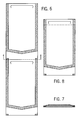
- the continuous web 10 is again formed from a base material 22 attached to a continuous strip of plastic film 24 by a layer of adhesive that defines the pair of side seals 26, 28 and the bottom seal 30.
- the adhesive seal defines an open end 34 for each of the bags.
- the second embodiment of the invention includes a die-cut slit 64 formed only in the base material 22.
- the die-cut slits 64 are spaced along the length of the continuous web such that each of the bags include one of the die-cut slits 64.
- the die-cut slit 64 includes a pair of curved ends 66, 68 that are each spaced inwardly from the side seals 26, 28, respectively. The die-cut slit 64 allows the automated bagging machine to separate the layer of base material and the plastic film to insert product into the pocket 32 formed in each of the bags.
- the die-cut slit 64 is not removed from the layer of base material, but instead is simply a die-cut that allows access to the pocket 32 through the layer of the base material 22.
- the die-cut slit 64 shown in the embodiment in the invention illustrated in Figs. 6-8 includes curved ends 66, 68, it should be understood that the die-cut slit could have other forms while operating in the scope of the present invention.
- the length of the die-cut slit 64 is selected to allow many types and sizes of products to be inserted into each of the bags formed along the continuous web 10.
- the length of the die-cut slit 64 could be decreased depending upon the type of product to be inserted. A decrease in the length of the die-cut slit 64 would reduce the size of the opening available to insert the product, but also would reduce the tendency of the bag to buckle during the insertion process.
- the bag 14 once separated from the continuous web, includes a heat seal 70 that is positioned beneath the die-cut slit 64 such that the open end 34 of the bag is sealed.
- the base material and the plastic film are attached to each other near the bottom end 48 by only the small portions of the side seals 26, 28.
- the bag 14 can be opened by peeling apart the base material and the plastic film along the bottom edge 48.
- the plastic film and the base material are peeled apart, the two layers separate along the chevron-shaped bottom seal 30 in a known manner.
- Figs. 9-12 thereshown is a third embodiment of the present invention.
- the continuous web 10 is also formed from several individual bags joined in an end-to-end configuration.
- the embodiment shown in Fig. 9 includes a die-cut opening 72 having a length between its side edges 74 and 76 that is significantly less than the length of the die-cut opening 36 shown in the first embodiment.
- the side edges 74, 76 of the die-cut opening 72 are spaced substantially inward from the pair of side seals 26, 28.
- the third embodiment shown in Fig. 9 includes a line of perforation 20 that bisects the die-cut opening 72.
- the line of perforation 20 defines a first area of perforation 78 and a second area of perforation 80 formed in the base material.
- the line of perforation 20 also extends completely across the plastic film as was the case in the first embodiment shown in Figs. 1-3. As can be seen in Fig.
- the first area of perforation 78 extends from the side edge 74 of the opening 72 to the side edge 16 of the web 10
- the second area of perforation 80 extends from the side edge 76 of the die-cut opening 72 to the side edge 18 of the continuous web 10.
- the die-cut opening 72 has a substantially smaller size than the first embodiment such that only small product can be inserted into the pocket 32 utilizing the insertion method shown in Figs. 4 and 5.
- This type of die-cut opening 72 allows granular and small products to be inserted into each of the individual bags without the bags rippling or folding during opening. Rippling or folding is a possibility due to the width of the die-cut opening 36 shown in the first embodiment of Figs. 1-3.
- the embodiment shown in Fig. 10 increases the effectiveness of the individual bags of the continuous web 10 to receive small and granular products.
- a unique loading device which is schematically shown in Figs. 10-11.
- a pair fingers 82, 84 are installed on the automated bagging machine and used during the filling process shown in Figs. 4 and 5.
- each of the fingers 82, 84 are inserted into the die-cut opening 72 such that the end 86 of each finger 82, 84 is received between the two layers of the individual bag.
- the fingers 82, 84 are moved toward the side edges 16, 18 of the continuous web, as shown by the arrows 88, 90 of Fig. 11. As the fingers 82, 84 move in this direction, the fingers 82, 84 tear the base material along the first area of perforation 78 and along the second area of perforation 80.
- the fingers 82, 84 are used to effectively expand the width of the die-cut opening 72 based upon the user requirement. As can be understood in Fig. 11, the user can select the width of the die-cut opening by controlling the distance the fingers 82, 84 are moved toward the lateral edges of the continuous web.
- product can be inserted into the individual bags using the steps discussed in Figs. 4 and 5.
- the use of the movable fingers 82, 84 enhances the usefulness of the single web of bags shown in Fig. 9, such that a single web can be used with a wider array of product sizes while providing an optimal opening for each.
Landscapes
- Engineering & Computer Science (AREA)
- Mechanical Engineering (AREA)
- Containers And Plastic Fillers For Packaging (AREA)
- Making Paper Articles (AREA)
- Bag Frames (AREA)
Applications Claiming Priority (2)
| Application Number | Priority Date | Filing Date | Title |
|---|---|---|---|
| US643688 | 2000-08-22 | ||
| US10/643,688 US20050041889A1 (en) | 2003-08-19 | 2003-08-19 | Continuous web of pre-opened medical bags |
Publications (2)
| Publication Number | Publication Date |
|---|---|
| EP1512636A2 true EP1512636A2 (de) | 2005-03-09 |
| EP1512636A3 EP1512636A3 (de) | 2005-05-04 |
Family
ID=34136593
Family Applications (1)
| Application Number | Title | Priority Date | Filing Date |
|---|---|---|---|
| EP04254979A Withdrawn EP1512636A3 (de) | 2003-08-19 | 2004-08-19 | Materialbahn von vorgeöffneten medizinischen Beuteln |
Country Status (2)
| Country | Link |
|---|---|
| US (1) | US20050041889A1 (de) |
| EP (1) | EP1512636A3 (de) |
Families Citing this family (9)
| Publication number | Priority date | Publication date | Assignee | Title |
|---|---|---|---|---|
| JP4451124B2 (ja) * | 2003-11-28 | 2010-04-14 | オリンパス株式会社 | 内視鏡用処置具挿抜システム |
| WO2008019385A1 (en) * | 2006-08-08 | 2008-02-14 | Kellogg Company | Flexible container for pourable product |
| US7874731B2 (en) | 2007-06-15 | 2011-01-25 | S.C. Johnson Home Storage, Inc. | Valve for a recloseable container |
| US7967509B2 (en) | 2007-06-15 | 2011-06-28 | S.C. Johnson & Son, Inc. | Pouch with a valve |
| CA3002553A1 (en) | 2015-11-16 | 2017-05-26 | Automated Packaging Systems, Inc. | Bag with cuts |
| US10124953B2 (en) | 2016-10-13 | 2018-11-13 | Altria Client Services Llc | Box in a box re-sealable cigarette pack |
| US10086987B2 (en) | 2016-10-13 | 2018-10-02 | Altria Client Services Llc | Reseal label for box in a box re-sealable pack |
| US10894658B2 (en) | 2018-03-06 | 2021-01-19 | Altria Client Services Llc | Re-sealable cigarette pack |
| US10450120B1 (en) | 2018-11-16 | 2019-10-22 | Altria Client Services Llc | Re-seal label and container with re-seal label |
Family Cites Families (10)
| Publication number | Priority date | Publication date | Assignee | Title |
|---|---|---|---|---|
| US3254828A (en) * | 1963-12-18 | 1966-06-07 | Automated Packaging Corp | Flexible container strips |
| US3935810A (en) * | 1972-01-31 | 1976-02-03 | Arvey Corporation | Pouches |
| US3926311A (en) * | 1974-08-22 | 1975-12-16 | Vonco Products Inc | Peel-seal containers |
| US3991881A (en) * | 1975-01-21 | 1976-11-16 | Propper Manufacturing Company, Inc. | Sterile pack |
| US4306656A (en) * | 1980-02-19 | 1981-12-22 | Dahlem A Richard | Medical pouches and a method of manufacturing such pouches |
| US4747815A (en) * | 1985-05-02 | 1988-05-31 | Mobil Oil Corporation | Collection of bags and method of preparing the same |
| US5301889A (en) * | 1986-05-16 | 1994-04-12 | Automated Packaging Systems, Inc. | Web dispensing apparatus |
| US4726970A (en) * | 1986-08-19 | 1988-02-23 | Morrish Stephen C | Packaging employing computer paper |
| US5007744A (en) * | 1989-12-21 | 1991-04-16 | Sharp Packaging, Inc. | Strips of interconnected pre-opened reclosable bags |
| US6419392B1 (en) * | 2000-11-02 | 2002-07-16 | Advanced Poly-Packaging, Inc. | Web of sterile bags for automatic bagging equipment |
-
2003
- 2003-08-19 US US10/643,688 patent/US20050041889A1/en not_active Abandoned
-
2004
- 2004-08-19 EP EP04254979A patent/EP1512636A3/de not_active Withdrawn
Also Published As
| Publication number | Publication date |
|---|---|
| EP1512636A3 (de) | 2005-05-04 |
| US20050041889A1 (en) | 2005-02-24 |
Similar Documents
| Publication | Publication Date | Title |
|---|---|---|
| US6986605B1 (en) | Multiwall vented bag, vented bag forming apparatus, and associated methods | |
| US5007744A (en) | Strips of interconnected pre-opened reclosable bags | |
| US5335478A (en) | Multi-compartment dispenser pouch and method of making | |
| US4402453A (en) | Pouch with closure seal strip and method for making same | |
| US20040022457A1 (en) | Plurality of bags and method of making the same | |
| WO2004092022A2 (en) | Closure for containers and reclosable containers including the same | |
| KR20080080673A (ko) | 개구 형상부를 갖는 가요성 패키지 | |
| AU2014216152A1 (en) | Packages having separable sealing features and methods of manufacturing | |
| WO2008048661A2 (en) | Reclosable package with protective patch | |
| US20240100800A1 (en) | Packaging with multi-ply walls | |
| GB2388832A (en) | Packaging for food items and a process for packaging such items | |
| US5221567A (en) | Packaging system | |
| US4581007A (en) | Adhesive closure bags and method for producing same | |
| US20050041889A1 (en) | Continuous web of pre-opened medical bags | |
| EP1263655B1 (de) | Wiederverschliessbarer beutel für nahrungsmittel sowie herstellungsverfahren | |
| EP0114383A2 (de) | Klebeverschluss für Säcke und Verfahren zu dessen Herstellung | |
| CN113795427A (zh) | 包装机及其使用方法 | |
| US7681375B2 (en) | Packaging machine for producing bag packages, and bag package | |
| CN108602575B (zh) | 带有切口的袋 | |
| NZ264733A (en) | Bag openable from either end: one end temporarily closed by strip of adhesive tape when bag is filled | |
| CN116438057A (zh) | 缓冲式可封闭袋的幅材 | |
| EP0423734A2 (de) | Verpackungssack zum Einsetzen in einer Publikation | |
| CA2610911A1 (en) | Method of forming and using a vented bag | |
| JPH11105957A (ja) | 使いすて衛生用品の包装袋 | |
| EP4719932A2 (de) | Aus dehnbarem papier hergestellte briefumschläge |
Legal Events
| Date | Code | Title | Description |
|---|---|---|---|
| PUAI | Public reference made under article 153(3) epc to a published international application that has entered the european phase |
Free format text: ORIGINAL CODE: 0009012 |
|
| AK | Designated contracting states |
Kind code of ref document: A2 Designated state(s): AT BE BG CH CY CZ DE DK EE ES FI FR GB GR HU IE IT LI LU MC NL PL PT RO SE SI SK TR |
|
| AX | Request for extension of the european patent |
Extension state: AL HR LT LV MK |
|
| PUAL | Search report despatched |
Free format text: ORIGINAL CODE: 0009013 |
|
| AK | Designated contracting states |
Kind code of ref document: A3 Designated state(s): AT BE BG CH CY CZ DE DK EE ES FI FR GB GR HU IE IT LI LU MC NL PL PT RO SE SI SK TR |
|
| AX | Request for extension of the european patent |
Extension state: AL HR LT LV MK |
|
| 17P | Request for examination filed |
Effective date: 20051024 |
|
| AKX | Designation fees paid |
Designated state(s): AT BE BG CH CY CZ DE DK EE ES FI FR GB GR HU IE IT LI LU MC NL PL PT RO SE SI SK TR |
|
| RAP1 | Party data changed (applicant data changed or rights of an application transferred) |
Owner name: SHARP PACKAGING SYSTEMS LLC |
|
| STAA | Information on the status of an ep patent application or granted ep patent |
Free format text: STATUS: THE APPLICATION IS DEEMED TO BE WITHDRAWN |
|
| 18D | Application deemed to be withdrawn |
Effective date: 20061017 |