EP1512606B1 - Organization trolley - Google Patents
Organization trolley Download PDFInfo
- Publication number
- EP1512606B1 EP1512606B1 EP03020214A EP03020214A EP1512606B1 EP 1512606 B1 EP1512606 B1 EP 1512606B1 EP 03020214 A EP03020214 A EP 03020214A EP 03020214 A EP03020214 A EP 03020214A EP 1512606 B1 EP1512606 B1 EP 1512606B1
- Authority
- EP
- European Patent Office
- Prior art keywords
- trolley
- vertical
- organisation
- supports
- transverse profiled
- Prior art date
- Legal status (The legal status is an assumption and is not a legal conclusion. Google has not performed a legal analysis and makes no representation as to the accuracy of the status listed.)
- Expired - Lifetime
Links
Images

Classifications
-
- A—HUMAN NECESSITIES
- A47—FURNITURE; DOMESTIC ARTICLES OR APPLIANCES; COFFEE MILLS; SPICE MILLS; SUCTION CLEANERS IN GENERAL
- A47L—DOMESTIC WASHING OR CLEANING; SUCTION CLEANERS IN GENERAL
- A47L13/00—Implements for cleaning floors, carpets, furniture, walls, or wall coverings
- A47L13/10—Scrubbing; Scouring; Cleaning; Polishing
- A47L13/50—Auxiliary implements
- A47L13/51—Storing of cleaning tools, e.g. containers therefor
-
- B—PERFORMING OPERATIONS; TRANSPORTING
- B62—LAND VEHICLES FOR TRAVELLING OTHERWISE THAN ON RAILS
- B62B—HAND-PROPELLED VEHICLES, e.g. HAND CARTS OR PERAMBULATORS; SLEDGES
- B62B2202/00—Indexing codes relating to type or characteristics of transported articles
- B62B2202/50—Cleaning or gardening articles
Definitions
- the invention relates to an organization trolley for the transport and storage of a variety of different objects, in particular cleaning utensils, with a chassis that carries wheels on its underside, and arranged in several levels superimposed compartments for receiving the objects to be transported.
- Such organization cars have long been known in various designs. They are used, for example, in the cleaning and care of buildings, in hotel service or as a mobile supply and disposal system.
- cleaning devices such as e.g. Buckets and cleaning utensils, cleaning products, toiletries, laundry or even containers for waste space in the compartments of the organization trolley.
- Basic module is always the chassis with the wheels, which then with a limited Number of components in the manner of a kit can be upgraded to an almost unlimited number of variants.
- a rack is constructed which supports, e.g. for more platforms, carries.
- the platform is designed as a flat plate and equipped with grid-mounted fastening devices.
- the frame consists of vertical supports, which can be coupled to the fastening devices of the platform.
- first latching means are provided on the vertical supports, which interact positively with second latching means on the holders.
- Organization trolleys and cleaning trolleys of the type described above usually have open structures, i. not only the individual elements of which they are composed but also the objects placed on them are openly accessible from all sides. This is disadvantageous in two respects: Firstly, the objects to be transported are neither protected against falling out nor against dust or unauthorized access; on the other hand, a packed organization trolley of a conventional nature does not provide a beautiful sight, as any visitor to a hospital or guest of a hotel will confirm.
- the task is therefore to develop a trolley with flexible modular design so that the objects transported on it are protected against falling out, dust and unauthorized access and at the same time the whole car receives a visually appealing appearance.
- the solution of this object is achieved by a trolley according to claim 1. Preferred embodiments will become apparent from the dependent claims.
- the base plate, the vertical supports and the transverse profile carriers form the load-bearing structure, which is supplemented by the vertical struts and flat cladding elements.
- the vertical beams form the side surfaces of the car which are closed by the fairing members. Since the vertical beams and the cladding elements do not belong to the supporting structure of the organization trolley, they can be relatively easily performed. As a result, the total weight of the company car is only marginally increased.
- Another advantage of the proposed construction is that, if desired, only a certain portion or even a single compartment of the carriage may be formed closed with trim elements while leaving other sections or compartments open. For example, only the front side and a longitudinal side of the car can be closed with cladding elements, while the compartments remain accessible from the opposite side.
- the organization trolley according to the invention can be optimally adapted to the respective application.
- an organization trolley which comprises a chassis with a base plate and a plurality of compartments arranged one above the other. On the bottom plate vertical spars are mounted, where flat cladding elements are attached. These trim elements extend over the entire height of the car.
- the cladding elements are inserted between two adjacent transverse profile carriers or between two transverse profile carriers and vertical bars, so that the transverse profile carriers and / or vertical bars are part of the closed outer wall.
- the vertical beams are part of the supporting structure, whereas in the organization trolley according to the invention, the vertical beams are mounted only when needed and for the purpose of the lining to the ends of the cross profile support to hold a cladding element.
- US 2002/0109318 A1 shows an organization trolley with chassis, wheels, vertical pillars and several storage compartments arranged one above the other. There are also large-scale trim elements such as a door and a front present.
- the organization trolley according to the invention has a modular structure of cross-member beams and vertical beams with intermediate flat trim parts, this modular structure for making a trim is independent of the supporting structure of the car.
- EP 0 645 129 A2 discloses a utensil trolley with a side element and a number of panel parts arranged one above the other.
- the back (see Figure 2) is formed by a lower panel and an upper panel.
- this prior art carriage does not show the separation according to the invention in a load-bearing structure and an independent modular modular panel comprising vertical profile support, vertical beams and intermediate flat panel elements.
- the vertical supports are arranged on the bottom plate in the grid.
- Base plate, vertical supports and cross-sectional support are preferably formed as described in the earlier application EP 03 000 752.0 the same applicant in detail.
- the mechanical connection between the cladding elements and the transverse profile carriers holding them is preferably effected by grooves which are provided in the region of the outer sides of the transverse profile carriers and into which the cladding element can be inserted with its upper or lower edge.
- the cladding elements can also be mechanically or otherwise connected in a fixed or detachable manner with the transverse profile carriers or the vertical beams, for example by a tongue and groove connection, connectors, clamping means or screws.
- the vertical bars at the ends of the cross profile support is preferably a positive clamping connection in the form of T-slots on the front sides of the cross profile and this carrier corresponding T-bars on the Vertical beams, which can be inserted into the T-slots of the cross-section beams from above or below.
- a useful addition to the organization trolley according to the invention is a horizontal end strip, which connects the upper ends of two adjacent vertical beams together.
- the end strip on its underside carry pins which engage in corresponding recesses in the end faces of the vertical beams.
- the end strip expediently comprises the upper edge of a flat paneling element.
- Such a trained end strip complements two parallel and spaced vertical beams to a frame that includes the cladding element. Since this end bar as well as the vertical bars has no supporting function, their outer shape can be designed mainly after aesthetic considerations.
- the end strip may have a closed smooth outer contour, which is important for hygiene and care reasons in an organization car, which is also used for cleaning purposes.
- the trim elements used between the cross-profile and the vertical beams can be easily formed as a flat cladding panels.
- the cladding elements can also be designed as openable doors, which are then pivotally mounted by means of a hinge to a vertical spar.
- the adjacent vertical spar can then be provided with a stop for the door. If the door is also equipped with a lock, individual compartments or also a whole section of the organization trolley can be firmly closed in order to secure the objects stored therein against unauthorized access.
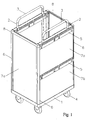
- the organization trolley exemplified in Figure 1 has a chassis which consists essentially of a rectangular bottom plate 1 and four vertical supports 2, which are firmly connected to the bottom plate 1.
- the vertical supports 2 are formed by round tubes. In each case two adjacent vertical supports 2 are connected to each other in the region of their upper end by a bracket 3.
- pivotable wheels 4 are screwed to the four corners.
- transverse profile support 5 are mounted vertically adjustable in height.
- the transverse profile support 5, the vertical supports 2 encompassing clamp elements.
- the transverse profile carrier 5 have holding and fastening means in the form of angled webs, clamping strips and grooves for holding (not shown) shelves.
- the structural design of the base plate 1, the vertical supports 2, the bracket 3 and in particular the cross-sectional member 5 and the connection technique used here are described in detail in the application EP 03 000 752.0 the same applicant.
- Base plate 1 vertical supports 2, 3 brackets and the cross-sectional support 5 form the modular structure and any expandable supporting structure of the organization car.
- Cladding elements in the form of planar cladding panels 7a, 7b are each between two transverse profile support 5 and two Vertical beams 6 used and form the side walls of the organization car.
- Two end strips 8 comprise the upper edges of the trim panels 7a.
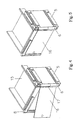
- the transverse profile carriers 5 have, in the region of their outsides, upwardly open grooves 9a and mirror-inverted grooves 9b, into which the upper or lower edges of the lining plate 7b are inserted.
- the vertical beams 6 also have mutually facing grooves 10a, 10b, which receive the left or right edge of the trim panel 7a used there.
- the cladding panel 7a can be easily inserted from above between the grooves 10a, 10b of two adjacent vertical beams 6, and as in a similar manner the cladding panel 7b from the front into the grooves 9a, 9b of two adjacent cross-sectional support 5 is inserted ,
- FIG. 2 also shows that the transverse profile carriers 5 have on their front side a vertically extending T-slot into which a corresponding T-bar 12 can be inserted on the rear side of the vertical bars 6.
- the end strip 8 is placed on the vertical beams 6 and the upper edge of the trim panel 7a.
- the end strip 8 carries at its bottom pin 13, which engage corresponding recesses 14 in the end faces of the vertical bars 6 by clamping.
- the vertical beams 6 and the end strip 8 have a smooth, rounded in the vertical edges outer contour.
- a door 16 is pivotally mounted as a cladding element 17 by means of a hinge 17 to the right of the vertical struts 6 to be seen there.
- the door 16 is shown in the closed state.
- Vertical beams 6, cladding panels 7a, 7b and end strips 8 can be combined with each other so that the organization trolley, for example, only on the front side and on a long side closed walls, whereas one side remains open to conveniently invite or remove items.
- additional doors 16 By means of additional doors 16, however, it is also possible to realize an organization trolley with side walls closed all around.
- the conclusion towards the top usually forms a removable shelf, which may for example be designed as a lateral tray 15, as shown in Figures 3, 4 and 5.
Landscapes
- Handcart (AREA)
- Holders For Apparel And Elements Relating To Apparel (AREA)
- Ropes Or Cables (AREA)
- Solid-Sorbent Or Filter-Aiding Compositions (AREA)
- Absorbent Articles And Supports Therefor (AREA)
Abstract
Description
Die Erfindung betrifft einen Organisationswagen zum Transport und zur Aufbewahrung einer Vielzahl von verschiedenen Gegenständen, insbesondere Reinigungsutensilien, mit einem Fahrgestell, das an seiner Unterseite Räder trägt, und mit in mehreren Ebenen übereinander angeordneten Fächern für die Aufnahme der zu transportierenden Gegenstände.The invention relates to an organization trolley for the transport and storage of a variety of different objects, in particular cleaning utensils, with a chassis that carries wheels on its underside, and arranged in several levels superimposed compartments for receiving the objects to be transported.
Derartige Organisationswagen sind in vielfältigen Ausführungen seit langem bekannt. Sie werden beispielsweise bei der Reinigung und Pflege von Gebäuden, im Hotel-Service oder als mobiles Ver- und Entsorgungssystem eingesetzt. Je nach Verwendungszweck finden Reinigungsgeräte wie z.B. Eimer und Putzgeräte, Reinigungsmittel, Toilettenartikel, Wäsche oder auch Behälter für Abfall Platz in den Fächern des Organisationswagens.Such organization cars have long been known in various designs. They are used, for example, in the cleaning and care of buildings, in hotel service or as a mobile supply and disposal system. Depending on the purpose, cleaning devices such as e.g. Buckets and cleaning utensils, cleaning products, toiletries, laundry or even containers for waste space in the compartments of the organization trolley.
Um den Wagen in Form und Größe an den gewünschten Einsatzzweck optimal anpassen zu können, weist er üblicherweise eine modulare Struktur auf. Grundmodul ist immer das Fahrgestell mit den Rädern, das dann mit einer begrenzten Anzahl von Bauelementen nach Art eines Baukastens zu einer fast unbegrenzten Zahl von Varianten aufgerüstet werden kann.In order to optimally adapt the car in shape and size to the desired application, it usually has a modular structure. Basic module is always the chassis with the wheels, which then with a limited Number of components in the manner of a kit can be upgraded to an almost unlimited number of variants.
In der älteren Anmeldung EP 03 000 752.0 desselben Anmelders ist ein aktueller, modular aufgebauter Transportwagen für Gegenstände beschrieben. Auf einer Plattform mit Rädern ist ein Gestell aufgebaut, welches Halterungen, z.B. für weitere Plattformen, trägt. Die Plattform ist als ebene Platte ausgebildet und mit im Raster angeordneten Befestigungseinrichtungen ausgestattet. Das Gestell besteht aus vertikalen Stützen, die an die Befestigungseinrichtungen der Plattform ankoppelbar sind. Hierzu sind an den vertikalen Stützen erste Einrastmittel vorgesehen, die mit zweiten Einrastmitteln an den Halterungen formschlüssig zusammenwirken.In the earlier application EP 03 000 752.0 of the same Applicant a current, modular construction trolley for objects is described. On a platform with wheels, a rack is constructed which supports, e.g. for more platforms, carries. The platform is designed as a flat plate and equipped with grid-mounted fastening devices. The frame consists of vertical supports, which can be coupled to the fastening devices of the platform. For this purpose, first latching means are provided on the vertical supports, which interact positively with second latching means on the holders.
Organisationswagen und Reinigungswagen der vorstehend beschriebenen Art haben üblicherweise offene Strukturen, d.h. nicht nur die einzelnen Elemente, aus denen sie zusammengesetzt sind, sondern auch die darauf abgestellten Gegenstände sind von allen Seiten offen zugänglich. Dies ist in zweierlei Hinsicht nachteilig: Zum einen sind die zu transportierenden Gegenstände weder gegen Herausfallen noch gegen Staub oder unbefugten Zugriff geschützt; zum anderen bietet ein vollgepackter Organisationswagen herkömmlicher Art keinen schönen Anblick, wie jeder Besucher eines Krankenhauses oder Gast eines Hotels bestätigen wird.Organization trolleys and cleaning trolleys of the type described above usually have open structures, i. not only the individual elements of which they are composed but also the objects placed on them are openly accessible from all sides. This is disadvantageous in two respects: Firstly, the objects to be transported are neither protected against falling out nor against dust or unauthorized access; on the other hand, a packed organization trolley of a conventional nature does not provide a beautiful sight, as any visitor to a hospital or guest of a hotel will confirm.
Die Aufgabe besteht also darin, einen Organisationswagen mit flexiblem modularen Aufbau so weiter zu entwickeln, dass die darauf transportierten Gegenstände gegen Herausfallen, Staub und unbefugten Zugriff geschützt sind und gleichzeitig der ganze Wagen ein optisch ansprechendes Erscheinungsbild erhält. Die Lösung dieser Aufgabe erfolgt durch einen Organisationswagen gemäß Anspruch 1. Bevorzugte Ausführungen ergeben sich aus den abhängigen Ansprüchen.The task is therefore to develop a trolley with flexible modular design so that the objects transported on it are protected against falling out, dust and unauthorized access and at the same time the whole car receives a visually appealing appearance. The solution of this object is achieved by a trolley according to claim 1. Preferred embodiments will become apparent from the dependent claims.
Bei dem erfindungsgemäßen Organisationswagen bilden die Bodenplatte, die Vertikalstützen und die Querprofilträger die tragende Struktur, welche um die Vertikalholme und flächige Verkleidungselemente ergänzt wird. Zusammen mit den Querprofilträgern bilden die Vertikalholme die Seitenflächen des Wagens, die von den Verkleidungselementen geschlossen werden. Da die Vertikalholme und die Verkleidungselemente nicht zur tragenden Struktur des Organisationswagens gehören, können sie relativ leicht ausgeführt werden. Das Gesamtgewicht des Organisationswagens erhöht sich dadurch nur unwesentlich. Ein weiterer Vorteil der vorgeschlagenen Konstruktion besteht darin, dass bei Bedarf nur ein bestimmter Abschnitt oder gar nur ein einzelnes Fach des Wagens mit Verkleidungselementen geschlossen ausgebildet werden kann, während andere Abschnitte bzw. Fächer offen bleiben. Beispielsweise lässt sich nur die Stirnseite und eine Längsseite des Wagens mit Verkleidungselementen schließen, während die Fächer von der gegenüberliegenden Seite her offen zugänglich bleiben. Damit lässt sich der erfindungsgemäße Organisationswagen dem jeweiligen Einsatzzweck optimal anpassen.In the case of the organization trolley according to the invention, the base plate, the vertical supports and the transverse profile carriers form the load-bearing structure, which is supplemented by the vertical struts and flat cladding elements. Together with the cross-member beams, the vertical beams form the side surfaces of the car which are closed by the fairing members. Since the vertical beams and the cladding elements do not belong to the supporting structure of the organization trolley, they can be relatively easily performed. As a result, the total weight of the company car is only marginally increased. Another advantage of the proposed construction is that, if desired, only a certain portion or even a single compartment of the carriage may be formed closed with trim elements while leaving other sections or compartments open. For example, only the front side and a longitudinal side of the car can be closed with cladding elements, while the compartments remain accessible from the opposite side. Thus, the organization trolley according to the invention can be optimally adapted to the respective application.
Aus der FR 2 833 913 A1 ist ein Organisationswagen bekannt, der ein Fahrgestell mit einer Bodenplatte und mehrere, übereinander angeordnete Fächer umfasst. Auf die Bodenplatte sind vertikale Holme montiert, an denen flächige Verkleidungselemente befestigt sind. Diese Verkleidungselemente erstrecken sich über die gesamte Höhe des Wagens. Bei dem erfindungsgemäßen Wagen dagegen sind die Verkleidungselemente zwischen zwei benachbarte Querprofilträger oder zwischen zwei Querprofilträger und Vertikalholme eingesetzt, so dass die Querprofilträger und/oder Vertikalholme Bestandteil der geschlossenen Außenwand sind. Beim Organisationswagen nach FR 2 833 913 A1 gehören die Vertikalholme mit zur tragenden Struktur, wohingegen beim Organisationswagen nach der Erfindung die Vertikalholme nur bei Bedarf und zum Zwecke der Verkleidung an die Enden der Querprofilträger montiert werden, um ein Verkleidungselement zu halten.From
Die US 2002/0109318 A1 zeigt einen Organisationswagen mit Fahrgestell, Rädern, vertikalen Stützpfeilern und mehreren, übereinander angeordneten Aufbewahrungsfächern. Es sind ferner großflächige Verkleidungselemente wie eine Tür und eine Front vorhanden. Demgegenüber hat der erfindungsgemäße Organisationswagen eine modulare Struktur aus Querprofilträgern und Vertikalholmen mit zwischengesetzten ebenen Verkleidungsteilen, wobei diese modulare Struktur zur Herstellung einer Verkleidung unabhängig von der tragenden Struktur des Wagens ist.US 2002/0109318 A1 shows an organization trolley with chassis, wheels, vertical pillars and several storage compartments arranged one above the other. There are also large-scale trim elements such as a door and a front present. In contrast, the organization trolley according to the invention has a modular structure of cross-member beams and vertical beams with intermediate flat trim parts, this modular structure for making a trim is independent of the supporting structure of the car.
Die EP 0 645 129 A2 offenbart einen Utensilienwagen mit einem Seitenelement und einer Anzahl übereinander angeordneter Paneelenteile. Die Rückseite (vergleiche Figur 2) wird von einem unteren Paneel und einem oberen Paneel gebildet. Auch dieser vorbekannte Wagen zeigt nicht die erfindungsgemäße Trennung in eine tragende Struktur und eine davon unabhängige, modulare aufgebaute Verkleidung, umfassend Vertikalprofilträger, Vertikalholme und zwischengesetzte flächige Verkleidungselemente.EP 0 645 129 A2 discloses a utensil trolley with a side element and a number of panel parts arranged one above the other. The back (see Figure 2) is formed by a lower panel and an upper panel. Also, this prior art carriage does not show the separation according to the invention in a load-bearing structure and an independent modular modular panel comprising vertical profile support, vertical beams and intermediate flat panel elements.
Bevorzugt wird eine Ausführung des Fahrgestells, bei der jeweils zwei benachbarte Vertikalstützen im Bereich Ihrer oberen Enden durch einen Bügel miteinander verbunden sind. Das erhöht die Stabilität der tragenden Struktur des Wagens.Preferred is an embodiment of the chassis, in which two adjacent vertical supports in the region of their upper ends are connected to each other by a bracket. This increases the stability of the supporting structure of the car.
Vorteilhaft sind die Vertikalstützen auf der Bodenplatte im Raster angeordnet. Bodenplatte, Vertikalstützen und Querprofilträger sind dabei vorzugsweise so ausgebildet, wie in der älteren Anmeldung EP 03 000 752.0 desselben Anmelders im Einzelnen beschrieben.Advantageously, the vertical supports are arranged on the bottom plate in the grid. Base plate, vertical supports and cross-sectional support are preferably formed as described in the earlier application EP 03 000 752.0 the same applicant in detail.
Die mechanische Verbindung zwischen den Verkleidungselementen und den diese haltenden Querprofilträgern geschieht vorzugsweise durch Nuten, die im Bereich der Außenseiten der Querprofilträger vorgesehen sind und in die das Verkleidungselement mit seinem oberen oder unteren Rand einschiebbar ist. In gleicher Weise dienen gegeneinander weisende Nuten an den Vertikalholmen zur Aufnahme der seitlichen Ränder eines Verkleidungselementes. Die Verkleidungselemente können aber auch in anderer Weise fest oder lösbar mit den Querprofilträgern bzw. den Vertikalholmen mechanisch verbunden werden, beispielsweise durch eine Nut- und Federverbindung, Steckverbindern, Klemmmitteln oder auch Schrauben.The mechanical connection between the cladding elements and the transverse profile carriers holding them is preferably effected by grooves which are provided in the region of the outer sides of the transverse profile carriers and into which the cladding element can be inserted with its upper or lower edge. In the same way serve mutually facing grooves on the vertical beams for receiving the lateral edges of a cladding element. But the cladding elements can also be mechanically or otherwise connected in a fixed or detachable manner with the transverse profile carriers or the vertical beams, for example by a tongue and groove connection, connectors, clamping means or screws.
Zur Befestigung der Vertikalholme an den Enden der Querprofilträger dient vorzugsweise eine formschlüssige Klemmverbindung in Form von T-Nuten an den Stirnseiten der Querprofilträger und hierzu korrespondierende T-Leisten an den Vertikalholmen, welche in die T-Nuten der Querprofilträger von oben oder unten einschiebbar sind.For fixing the vertical bars at the ends of the cross profile support is preferably a positive clamping connection in the form of T-slots on the front sides of the cross profile and this carrier corresponding T-bars on the Vertical beams, which can be inserted into the T-slots of the cross-section beams from above or below.
Eine sinnvolle Ergänzung des erfindungsgemäßen Organisationswagens stellt eine horizontale Abschlussleiste dar, welche die oberen Enden zweier benachbarter Vertikalholme miteinander verbindet. Hierzu kann die Abschlussleiste an ihrer Unterseite Zapfen tragen, welche in korrespondierende Aussparungen in den Stirnseiten der Vertikalholme eingreifen. Zweckmäßig umfasst die Abschlussleiste den oberen Rand eines flächigen Verkleidungselementes. Eine derart ausgebildete Abschlussleiste ergänzt zwei, parallel und im Abstand zueinander angeordnete Vertikalholme zu einem Rahmen, der das Verkleidungselement umfasst. Da auch diese Abschlussleiste ebenso wie die Vertikalholme keine tragende Funktion hat, kann ihre äußere Form vor allem nach ästhetischen Gesichtspunkten gestaltet werden. Insbesondere kann die Abschlussleiste eine geschlossene glatte Außenkontur aufweisen, was bei einem Organisationswagen, der auch für Reinigungszwecke eingesetzt wird, aus Hygiene- und Pflegegründen wichtig ist.A useful addition to the organization trolley according to the invention is a horizontal end strip, which connects the upper ends of two adjacent vertical beams together. For this purpose, the end strip on its underside carry pins which engage in corresponding recesses in the end faces of the vertical beams. The end strip expediently comprises the upper edge of a flat paneling element. Such a trained end strip complements two parallel and spaced vertical beams to a frame that includes the cladding element. Since this end bar as well as the vertical bars has no supporting function, their outer shape can be designed mainly after aesthetic considerations. In particular, the end strip may have a closed smooth outer contour, which is important for hygiene and care reasons in an organization car, which is also used for cleaning purposes.
Die zwischen die Querprofilträger und die Vertikalholme eingesetzten Verkleidungselemente können einfach als ebene Verkleidungsplatten ausgebildet sein. Die Verkleidungselemente können aber auch als öffenbare Türen ausgebildet sein, die dann mittels eines Scharniers an einem Vertikalholm schwenkbar befestigt sind. Der benachbarte Vertikalholm kann dann mit einem Anschlag für die Tür versehen werden. Ist die Tür zudem mit einem Schloss ausgerüstet, so können einzelne Fächer oder auch ein ganzer Abschnitt des Organisationswagens fest verschlossen werden, um die darin aufbewahrten Gegenstände gegen unbefugten Zugriff zu sichern.The trim elements used between the cross-profile and the vertical beams can be easily formed as a flat cladding panels. The cladding elements can also be designed as openable doors, which are then pivotally mounted by means of a hinge to a vertical spar. The adjacent vertical spar can then be provided with a stop for the door. If the door is also equipped with a lock, individual compartments or also a whole section of the organization trolley can be firmly closed in order to secure the objects stored therein against unauthorized access.
Ein Ausführungsbeispiel der Erfindung wird nachstehend anhand der beigefügten Zeichnungen näher beschrieben. Es zeigen:
- Figur 1
- einen Organisationswagen mit geschlossen ausgebildeten Seitenwänden, in einer perspektivischen Ansicht schräg von oben;
Figur 2- die obere linke Ecke des Organisationswagens von Figur 1, in einer Explosionsdarstellung;
Figur 3- die Ecke von
Figur 2 mit teilweise geschnitten dargestellten Einzelteilen und eine zusätzliche Wanne; Figur 4- die Ecke eines Organisationswagen ähnlich wie in
Figur 2, mit einer Tür in geöffnetem Zustand; Figur 5- die Ecke des Organisationswagens von
Figur 4 mit geschlossener Tür.
- FIG. 1
- an organization car with closed side walls, in a perspective view obliquely from above;
- FIG. 2
- the upper left corner of the organization trolley of Figure 1, in an exploded view;
- FIG. 3
- the corner of Figure 2 with parts shown partially cut and an additional tray;
- FIG. 4
- the corner of an organization cart similar to that in Figure 2, with a door in the open state;
- FIG. 5
- the corner of the organization car of Figure 4 with the door closed.
Der in Figur 1 beispielhaft dargestellte Organisationswagen hat ein Fahrgestell, das im Wesentlichen aus einer rechteckigen Bodenplatte 1 und vier Vertikalstützen 2 besteht, die mit der Bodenplatte 1 fest verbunden sind. Die Vertikalstützen 2 sind von Rundrohren gebildet. Jeweils zwei benachbarte Vertikalstützen 2 sind im Bereich ihres oberen Endes durch einen Bügel 3 miteinander verbunden. An der Unterseite der Bodenplatte 1 sind an den vier Ecken schwenkbare Räder 4 angeschraubt.The organization trolley exemplified in Figure 1 has a chassis which consists essentially of a rectangular bottom plate 1 and four
An den Vertikalstützen 2 sind Querprofilträger 5 aus Kunststoff höhenverschiebbar befestigt. Hierzu weisen die Querprofilträger 5 die Vertikalstützen 2 umgreifende Klammerelemente auf. Die Querprofilträger 5 weisen Halte- und Befestigungsmittel in Form von abgewinkelten Stegen, Klemmleisten und Nuten zur Halterung von (nicht dargestellten) Fachböden auf. Die konstruktive Ausgestaltung der Bodenplatte 1, der Vertikalstützen 2, des Bügels 3 und insbesondere der Querprofilträger 5 sowie die hier verwendete Verbindungstechnik sind in der Anmeldung EP 03 000 752.0 desselben Anmelders im Detail beschrieben.On the
Bodenplatte 1, Vertikalstützen 2, Bügel 3 und die Querprofilträger 5 bilden die modular aufgebaute und beliebig erweiterbare tragende Struktur des Organisationswagens.Base plate 1,
An den vorderen und hinteren Enden der Querprofilträger 5 sind insgesamt vier Vertikalholme 6 befestigt. Verkleidungselemente in Form von ebenen Verkleidungsplatten 7a, 7b sind jeweils zwischen zwei Querprofilträger 5 bzw. zwei Vertikalholme 6 eingesetzt und bilden die Seitenwände des Organisationswagens. Zwei Abschlussleisten 8 umfassen die oberen Ränder der Verkleidungsplatten 7a.At the front and rear ends of the cross-sectional member 5 a total of four
Wie in den Figuren 2 und 3 erkennbar, weisen die Querprofilträger 5 im Bereich ihrer Außenseiten nach oben offene Nuten 9a und spiegelbildlich nach unten offene Nuten 9b auf, in welche die oberen bzw. unteren Ränder der Verkleidungsplatte 7b eingeschoben sind. Die Vertikalholme 6 weisen gleichfalls gegeneinander weisende Nuten 10a, 10b auf, welche den linken bzw. rechten Rand der dort eingesetzten Verkleidungsplatte 7a aufnehmen.As can be seen in FIGS. 2 and 3, the
Insbesondere aus Figur 2 wird deutlich, dass die Verkleidungsplatte 7a einfach von oben zwischen die Nuten 10a, 10b zweier benachbarter Vertikalholme 6 eingeschoben werden kann, und wie in ähnlicher Weise die Verkleidungsplatte 7b von vorne in die Nuten 9a, 9b zweier benachbarter Querprofilträger 5 einschiebbar ist.In particular, from Figure 2 it is clear that the
In Figur 2 lässt sich ferner erkennen, dass die Querprofilträger 5 an ihrer Stirnseite eine vertikal verlaufende T-Nut aufweisen, in welche eine korrespondierende T-Leiste 12 an der Rückseite der Vertikalholme 6 einschiebbar sind. Zum Schluss wird die Abschlussleiste 8 auf die Vertikalholme 6 und den oberen Rand der Verkleidungsplatte 7a aufgesetzt. Hierzu trägt die Abschlussleiste 8 an ihrer Unterseite Zapfen 13, welche korrespondierende Aussparungen 14 in den Stirnseiten der Vertikalholme 6 klemmend eingreifen. Die Vertikalholme 6 und die Abschlussleiste 8 weisen eine glatte, im Bereich der vertikalen Kanten abgerundete Außenkontur auf.FIG. 2 also shows that the
Die Montage der Vertikalholme 6, der Verkleidungsplatten 7a bzw. 7b und der Abschlussleiste 8 erfordern kein Werkzeug und können vom Benutzer auch jederzeit nachträglich und bedarfsweise durchgeführt werden.The installation of the
In Figur 4 ist als Verkleidungselement eine Tür 16 mittels eines Scharniers 17 an den rechten der dort zu sehenden Vertikalholme 6 schwenkbar befestigt. In Figur 5 ist die Tür 16 in geschlossenem Zustand dargestellt.In Figure 4, a
Vertikalholme 6, Verkleidungsplatten 7a, 7b und Abschlussleisten 8 können so miteinander kombiniert werden, dass der Organisationswagen z.B. nur an der Stirnseite und an einer Längsseite geschlossene Wände hat, wohingegen eine Seite offen bleibt, um bequem Gegenstände einzuladen oder herauszunehmen. Mittels zusätzlicher Türen 16 lässt sich aber auch ein Organisationswagen mit ringsum geschlossenen Seitenwänden realisieren. Den Abschluss nach oben hin bildet in der Regel ein herausnehmbarer Fachboden, der beispielsweise als seitliche Wanne 15 ausgeführt sein kann, wie in den Figuren 3, 4 und 5 dargestellt.
- 11
- Bodenplattebaseplate
- 22
- Vertikalstützevertical support
- 33
- Bügelhanger
- 44
- Radwheel
- 55
- QuerprofilträgerCross profiles
- 66
- Vertikalholmvertical beam
- 7a, 7b7a, 7b
- Verkleidungsplattencladding panels
- 88th
- Abschlussleisteend strip
- 9a, 9b9a, 9b
- Nuten (in 5)Grooves (in 5)
- 10a, 10b10a, 10b
- Nuten (in 6)Grooves (in 6)
- 1111
- T-Nut (an 5)T-slot (to 5)
- 1212
- T-Leiste (an 6)T-bar (to 6)
- 1313
- Zapfen (von 8)Cones (from 8)
- 1414
- Aussparung (in 6)Recess (in 6)
- 1515
- Wannetub
- 1616
- Türdoor
- 1717
- Scharnier (von 16)Hinge (of 16)
- 1818
- Wannetub
Claims (10)
- An organisation trolley for transporting and storing a plurality of different articles, particularly cleaning utensils, including- compartments arranged above one another in a plurality of planes for accommodating the articles to be transported- a frame, which includes a base plate (1) and vertical pillars (2) arranged on it and carries wheels (4) on its underside;- a number of transverse profiled supports (5), which are each secured to at least one vertical pillar (2) and include retaining means for compartment bases;- wherein the base plate (1), vertical pillars (2) and the transverse profiled supports (5) constitute the support structure of the organisation trolley;- at least two additional vertical struts (6), which may be attached to the support structure and are each connected to the ends of at least two adjacent transverse profiled supports (5);- laminar cover elements, which are inserted between two adjacent transverse profiled supports (5) and/or vertical struts (6)
- An organisation trolley as claimed in Claim 1, characterised in that two adjacent vertical supports (2) are connected together in the region of their upper ends by a respective handle (3).
- An organisation trolley as claimed in Claim 1 or 2, characterised in that the vertical supports (2) are arranged on the base plate (1) in a grid.
- An organisation trolley as claimed in one of Claims 1 to 3, characterised in that the transverse profiled supports (4) have grooves (9a, 9b) in the region of their outer surfaces, into which the edge of a cover element may be inserted.
- An organisation trolley as claimed in one of Claims 1 - 4, characterised in that the vertical struts have grooves (10a, 10b) directed towards one another, into which the edge of a cover element may be inserted.
- An organisation trolley as claimed in one of Claims 1 - 3 characterised in that- the transverse profiled supports (5) have a vertically extending T-shaped groove (11) on at least one end surface;- the vertical struts have corresponding T-shaped bars (12), which may be inserted into the T-shaped grooves in the transverse profiled supports.
- An organisation trolley as claimed in one of Claims 1 - 6, characterised by a horizontal termination bar (8), which connects the upper ends of two adjacent vertical struts (6) together and surrounds the upper edge of a cover element.
- An organization trolley as claimed in Claim 7, characterised in that the termination bar (8) has pegs (13) on its underside which engage into corresponding openings (14) in the end surfaces of the vertical struts (6).
- An organisation trolley as claimed in one of Claims 1 - 8, characterised in that the cover elements are constructed in the form of flat cover plates (7a, 7b).
- An organisation trolley as claimed in one of Claims 1 - 8, characterised in that the cover elements are constructed in the form of openable doors (16), which are pivotably connected to a vertical strut by means of a hinge (17).
Priority Applications (7)
| Application Number | Priority Date | Filing Date | Title |
|---|---|---|---|
| ES03020214T ES2275052T3 (en) | 2003-09-06 | 2003-09-06 | ORGANIZATION CART. |
| DE50305502T DE50305502D1 (en) | 2003-09-06 | 2003-09-06 | An organization trolley |
| PT03020214T PT1512606E (en) | 2003-09-06 | 2003-09-06 | Organization trolley |
| SI200330618T SI1512606T1 (en) | 2003-09-06 | 2003-09-06 | Organization trolley |
| EP03020214A EP1512606B1 (en) | 2003-09-06 | 2003-09-06 | Organization trolley |
| AT03020214T ATE343504T1 (en) | 2003-09-06 | 2003-09-06 | ORGANIZATION TROLLEY |
| DK03020214T DK1512606T3 (en) | 2003-09-06 | 2003-09-06 | An organization trolley |
Applications Claiming Priority (1)
| Application Number | Priority Date | Filing Date | Title |
|---|---|---|---|
| EP03020214A EP1512606B1 (en) | 2003-09-06 | 2003-09-06 | Organization trolley |
Publications (2)
| Publication Number | Publication Date |
|---|---|
| EP1512606A1 EP1512606A1 (en) | 2005-03-09 |
| EP1512606B1 true EP1512606B1 (en) | 2006-10-25 |
Family
ID=34130158
Family Applications (1)
| Application Number | Title | Priority Date | Filing Date |
|---|---|---|---|
| EP03020214A Expired - Lifetime EP1512606B1 (en) | 2003-09-06 | 2003-09-06 | Organization trolley |
Country Status (7)
| Country | Link |
|---|---|
| EP (1) | EP1512606B1 (en) |
| AT (1) | ATE343504T1 (en) |
| DE (1) | DE50305502D1 (en) |
| DK (1) | DK1512606T3 (en) |
| ES (1) | ES2275052T3 (en) |
| PT (1) | PT1512606E (en) |
| SI (1) | SI1512606T1 (en) |
Cited By (2)
| Publication number | Priority date | Publication date | Assignee | Title |
|---|---|---|---|---|
| DE102007010937A1 (en) * | 2007-03-07 | 2008-09-11 | Melchert, Franz Adolf | Maid's trolley with lockable compartments or lockable storage shelf |
| DE102010032962A1 (en) | 2010-07-30 | 2012-02-02 | Wanzl Metallwarenfabrik Gmbh | Transport container for transporting laundry in hotel, has pivotable doors which are arranged at front side of container, and concealably arranged at sidewalls inside container |
Families Citing this family (4)
| Publication number | Priority date | Publication date | Assignee | Title |
|---|---|---|---|---|
| WO2010051841A1 (en) | 2008-11-05 | 2010-05-14 | Ecolab Inc. | Cleaning trolley |
| DK2314497T3 (en) * | 2009-10-22 | 2014-10-27 | Vermop Salmon Gmbh | Transport trolley for cleaning utensils |
| DE102017010460A1 (en) * | 2017-11-13 | 2019-05-16 | Carl Freudenberg Kg | Cleaning trolley and method for its assembly |
| DE102020111731A1 (en) | 2020-04-29 | 2021-11-04 | Alfred Kärcher SE & Co. KG | Cleaning trolley |
Family Cites Families (4)
| Publication number | Priority date | Publication date | Assignee | Title |
|---|---|---|---|---|
| US5016948A (en) * | 1989-02-02 | 1991-05-21 | Intermetro Industries Corporation | Modular utility cart |
| DE10064490C1 (en) * | 2000-12-22 | 2002-03-14 | Henkel Ecolab Gmbh & Co Ohg | Transport trolley for cleaning materials has outwards opening storage compartments in space between wheeled chassis and lowermost storage tray |
| US6827357B2 (en) * | 2001-02-09 | 2004-12-07 | Akro-Mils, A Division Of Myers Industries Company | Janitorial cart |
| ITMI20010670U1 (en) * | 2001-12-20 | 2003-06-20 | Vdm Srl | TROLLEY EQUIPPED FOR THE CLEANING OF ENVIRONMENTS IN PARTICULAR OF ENVIRONMENTS TYPE HOSPITALS HOTELS OFFICES OFFICES COMMUNITY OR SIMILAR TO HIGH |
-
2003
- 2003-09-06 DK DK03020214T patent/DK1512606T3/en active
- 2003-09-06 EP EP03020214A patent/EP1512606B1/en not_active Expired - Lifetime
- 2003-09-06 SI SI200330618T patent/SI1512606T1/en unknown
- 2003-09-06 DE DE50305502T patent/DE50305502D1/en not_active Expired - Lifetime
- 2003-09-06 AT AT03020214T patent/ATE343504T1/en active
- 2003-09-06 ES ES03020214T patent/ES2275052T3/en not_active Expired - Lifetime
- 2003-09-06 PT PT03020214T patent/PT1512606E/en unknown
Cited By (3)
| Publication number | Priority date | Publication date | Assignee | Title |
|---|---|---|---|---|
| DE102007010937A1 (en) * | 2007-03-07 | 2008-09-11 | Melchert, Franz Adolf | Maid's trolley with lockable compartments or lockable storage shelf |
| DE102010032962A1 (en) | 2010-07-30 | 2012-02-02 | Wanzl Metallwarenfabrik Gmbh | Transport container for transporting laundry in hotel, has pivotable doors which are arranged at front side of container, and concealably arranged at sidewalls inside container |
| DE202010018158U1 (en) | 2010-07-30 | 2014-11-05 | Wanzl Metallwarenfabrik Gmbh | Shipping containers |
Also Published As
| Publication number | Publication date |
|---|---|
| DE50305502D1 (en) | 2006-12-07 |
| PT1512606E (en) | 2007-02-28 |
| EP1512606A1 (en) | 2005-03-09 |
| SI1512606T1 (en) | 2007-04-30 |
| DK1512606T3 (en) | 2007-02-26 |
| ATE343504T1 (en) | 2006-11-15 |
| ES2275052T3 (en) | 2007-06-01 |
Similar Documents
| Publication | Publication Date | Title |
|---|---|---|
| DE69702821T2 (en) | Collapsible container for aircraft | |
| DE4324628A1 (en) | Device for providing tools and materials | |
| DE9313158U1 (en) | Storage and transport cases for lighting equipment | |
| CH659229A5 (en) | PORTABLE storage and / OR LAGERBEHAELTER FOR SMALL PARTS OR THE LIKE. | |
| DE2339808A1 (en) | CONTAINER FOR MODULAR SYSTEM | |
| DE102005058954B4 (en) | Rear luggage rack for a hatchback vehicle | |
| EP1772389A1 (en) | Large load carrier | |
| DE19737712B4 (en) | Charging system for a storage space of a vehicle | |
| EP1608922A1 (en) | Device for receiving goods to be cooled in a refrigerator | |
| EP1512606B1 (en) | Organization trolley | |
| DE69117773T2 (en) | SHELVING SYSTEM FOR VAN VEHICLES | |
| DE102005020613B4 (en) | Module carrier for a driver's cab and method for equipping a driver's cab of a motor vehicle with furniture elements | |
| EP2424762A1 (en) | Apparatus for transporting stage equipment | |
| EP1987735B2 (en) | Block shelving for storage, in particular bicycles | |
| DE4006874C1 (en) | ||
| WO2005085035A2 (en) | Stackable shopping trolley | |
| DE102008011785B3 (en) | Mounting, transporting and sequence wagon for accommodating different storage material, has drawer consists of rotary box profile frame and carrier arranged inside box profile frame, and box shaped container consists of support | |
| EP1362760B1 (en) | Damping device for a non motorized trolley and trolley | |
| EP1043188A2 (en) | Arrangements in a loading space for transport vehicles or containers | |
| DE19500531A1 (en) | Trolley for carrying multiple trays | |
| DE4306525C1 (en) | Open-top shopping basket with intermediate bottoms - has ribs on wall inside with supports for false bottoms with adjustable partitions inserted from top | |
| EP1142511A1 (en) | A device for receiving a plurality of containers | |
| DE3310873A1 (en) | Transportable supply and/or storage container for small parts or the like | |
| DE29720097U1 (en) | Fridge door | |
| DE2109666B2 (en) | Box-shaped transport container for large, bulky goods |
Legal Events
| Date | Code | Title | Description |
|---|---|---|---|
| PUAI | Public reference made under article 153(3) epc to a published international application that has entered the european phase |
Free format text: ORIGINAL CODE: 0009012 |
|
| AK | Designated contracting states |
Kind code of ref document: A1 Designated state(s): AT BE BG CH CY CZ DE DK EE ES FI FR GB GR HU IE IT LI LU MC NL PT RO SE SI SK TR |
|
| AX | Request for extension of the european patent |
Extension state: AL LT LV MK |
|
| 17P | Request for examination filed |
Effective date: 20050712 |
|
| AKX | Designation fees paid |
Designated state(s): AT BE BG CH CY CZ DE DK EE ES FI FR GB GR HU IE IT LI LU MC NL PT RO SE SI SK TR |
|
| GRAP | Despatch of communication of intention to grant a patent |
Free format text: ORIGINAL CODE: EPIDOSNIGR1 |
|
| GRAS | Grant fee paid |
Free format text: ORIGINAL CODE: EPIDOSNIGR3 |
|
| GRAA | (expected) grant |
Free format text: ORIGINAL CODE: 0009210 |
|
| AK | Designated contracting states |
Kind code of ref document: B1 Designated state(s): AT BE BG CH CY CZ DE DK EE ES FI FR GB GR HU IE IT LI LU MC NL PT RO SE SI SK TR |
|
| REG | Reference to a national code |
Ref country code: GB Ref legal event code: FG4D Free format text: NOT ENGLISH |
|
| REG | Reference to a national code |
Ref country code: CH Ref legal event code: EP |
|
| REG | Reference to a national code |
Ref country code: IE Ref legal event code: FG4D Free format text: LANGUAGE OF EP DOCUMENT: GERMAN |
|
| REF | Corresponds to: |
Ref document number: 50305502 Country of ref document: DE Date of ref document: 20061207 Kind code of ref document: P |
|
| REG | Reference to a national code |
Ref country code: RO Ref legal event code: EPE Ref country code: CH Ref legal event code: NV Representative=s name: TROESCH SCHEIDEGGER WERNER AG |
|
| REG | Reference to a national code |
Ref country code: SE Ref legal event code: TRGR |
|
| REG | Reference to a national code |
Ref country code: GR Ref legal event code: EP Ref document number: 20070400049 Country of ref document: GR Ref country code: EE Ref legal event code: FG4A Ref document number: E000770 Country of ref document: EE Effective date: 20061222 |
|
| GBT | Gb: translation of ep patent filed (gb section 77(6)(a)/1977) |
Effective date: 20070125 |
|
| REG | Reference to a national code |
Ref country code: DK Ref legal event code: T3 |
|
| REG | Reference to a national code |
Ref country code: PT Ref legal event code: SC4A Free format text: AVAILABILITY OF NATIONAL TRANSLATION Effective date: 20070116 |
|
| ET | Fr: translation filed | ||
| REG | Reference to a national code |
Ref country code: HU Ref legal event code: AG4A Ref document number: E001188 Country of ref document: HU |
|
| REG | Reference to a national code |
Ref country code: ES Ref legal event code: FG2A Ref document number: 2275052 Country of ref document: ES Kind code of ref document: T3 |
|
| PLBE | No opposition filed within time limit |
Free format text: ORIGINAL CODE: 0009261 |
|
| STAA | Information on the status of an ep patent application or granted ep patent |
Free format text: STATUS: NO OPPOSITION FILED WITHIN TIME LIMIT |
|
| 26N | No opposition filed |
Effective date: 20070726 |
|
| PGFP | Annual fee paid to national office [announced via postgrant information from national office to epo] |
Ref country code: TR Payment date: 20070823 Year of fee payment: 5 |
|
| PGFP | Annual fee paid to national office [announced via postgrant information from national office to epo] |
Ref country code: BG Payment date: 20070817 Year of fee payment: 5 Ref country code: EE Payment date: 20070918 Year of fee payment: 5 |
|
| PG25 | Lapsed in a contracting state [announced via postgrant information from national office to epo] |
Ref country code: CY Free format text: LAPSE BECAUSE OF NON-PAYMENT OF DUE FEES Effective date: 20070906 |
|
| REG | Reference to a national code |
Ref country code: EE Ref legal event code: MM4A Ref document number: E000770 Country of ref document: EE Effective date: 20080930 |
|
| PG25 | Lapsed in a contracting state [announced via postgrant information from national office to epo] |
Ref country code: EE Free format text: LAPSE BECAUSE OF NON-PAYMENT OF DUE FEES Effective date: 20080930 |
|
| PG25 | Lapsed in a contracting state [announced via postgrant information from national office to epo] |
Ref country code: BG Free format text: LAPSE BECAUSE OF NON-PAYMENT OF DUE FEES Effective date: 20080930 |
|
| PG25 | Lapsed in a contracting state [announced via postgrant information from national office to epo] |
Ref country code: TR Free format text: LAPSE BECAUSE OF NON-PAYMENT OF DUE FEES Effective date: 20100916 |
|
| PG25 | Lapsed in a contracting state [announced via postgrant information from national office to epo] |
Ref country code: TR Free format text: LAPSE BECAUSE OF NON-PAYMENT OF DUE FEES Effective date: 20080906 |
|
| PGFP | Annual fee paid to national office [announced via postgrant information from national office to epo] |
Ref country code: SK Payment date: 20130904 Year of fee payment: 11 Ref country code: FI Payment date: 20130919 Year of fee payment: 11 Ref country code: RO Payment date: 20130830 Year of fee payment: 11 Ref country code: LU Payment date: 20130925 Year of fee payment: 11 Ref country code: SI Payment date: 20130827 Year of fee payment: 11 Ref country code: MC Payment date: 20130920 Year of fee payment: 11 Ref country code: GR Payment date: 20130918 Year of fee payment: 11 |
|
| PG25 | Lapsed in a contracting state [announced via postgrant information from national office to epo] |
Ref country code: MC Free format text: LAPSE BECAUSE OF NON-PAYMENT OF DUE FEES Effective date: 20140930 Ref country code: FI Free format text: LAPSE BECAUSE OF NON-PAYMENT OF DUE FEES Effective date: 20140906 Ref country code: RO Free format text: LAPSE BECAUSE OF NON-PAYMENT OF DUE FEES Effective date: 20140906 Ref country code: LU Free format text: LAPSE BECAUSE OF NON-PAYMENT OF DUE FEES Effective date: 20140906 |
|
| REG | Reference to a national code |
Ref country code: GR Ref legal event code: ML Ref document number: 20070400049 Country of ref document: GR Effective date: 20150403 |
|
| REG | Reference to a national code |
Ref country code: SK Ref legal event code: MM4A Ref document number: E 1324 Country of ref document: SK Effective date: 20140906 |
|
| REG | Reference to a national code |
Ref country code: SI Ref legal event code: KO00 Effective date: 20150504 |
|
| PG25 | Lapsed in a contracting state [announced via postgrant information from national office to epo] |
Ref country code: SI Free format text: LAPSE BECAUSE OF NON-PAYMENT OF DUE FEES Effective date: 20140907 Ref country code: SK Free format text: LAPSE BECAUSE OF NON-PAYMENT OF DUE FEES Effective date: 20140906 |
|
| PG25 | Lapsed in a contracting state [announced via postgrant information from national office to epo] |
Ref country code: GR Free format text: LAPSE BECAUSE OF NON-PAYMENT OF DUE FEES Effective date: 20150403 |
|
| PGFP | Annual fee paid to national office [announced via postgrant information from national office to epo] |
Ref country code: CZ Payment date: 20150902 Year of fee payment: 13 Ref country code: PT Payment date: 20150828 Year of fee payment: 13 Ref country code: ES Payment date: 20150923 Year of fee payment: 13 Ref country code: IE Payment date: 20150928 Year of fee payment: 13 |
|
| PGFP | Annual fee paid to national office [announced via postgrant information from national office to epo] |
Ref country code: SE Payment date: 20150922 Year of fee payment: 13 Ref country code: HU Payment date: 20150914 Year of fee payment: 13 |
|
| PGFP | Annual fee paid to national office [announced via postgrant information from national office to epo] |
Ref country code: DK Payment date: 20150923 Year of fee payment: 13 |
|
| REG | Reference to a national code |
Ref country code: FR Ref legal event code: PLFP Year of fee payment: 14 |
|
| REG | Reference to a national code |
Ref country code: DK Ref legal event code: EBP Effective date: 20160930 |
|
| PG25 | Lapsed in a contracting state [announced via postgrant information from national office to epo] |
Ref country code: SE Free format text: LAPSE BECAUSE OF NON-PAYMENT OF DUE FEES Effective date: 20160907 |
|
| REG | Reference to a national code |
Ref country code: SE Ref legal event code: EUG |
|
| PG25 | Lapsed in a contracting state [announced via postgrant information from national office to epo] |
Ref country code: CZ Free format text: LAPSE BECAUSE OF NON-PAYMENT OF DUE FEES Effective date: 20160906 Ref country code: PT Free format text: LAPSE BECAUSE OF NON-PAYMENT OF DUE FEES Effective date: 20170306 |
|
| REG | Reference to a national code |
Ref country code: IE Ref legal event code: MM4A |
|
| PG25 | Lapsed in a contracting state [announced via postgrant information from national office to epo] |
Ref country code: IE Free format text: LAPSE BECAUSE OF NON-PAYMENT OF DUE FEES Effective date: 20160906 |
|
| PG25 | Lapsed in a contracting state [announced via postgrant information from national office to epo] |
Ref country code: HU Free format text: LAPSE BECAUSE OF NON-PAYMENT OF DUE FEES Effective date: 20160907 |
|
| REG | Reference to a national code |
Ref country code: FR Ref legal event code: PLFP Year of fee payment: 15 |
|
| PG25 | Lapsed in a contracting state [announced via postgrant information from national office to epo] |
Ref country code: DK Free format text: LAPSE BECAUSE OF NON-PAYMENT OF DUE FEES Effective date: 20160930 |
|
| PG25 | Lapsed in a contracting state [announced via postgrant information from national office to epo] |
Ref country code: ES Free format text: LAPSE BECAUSE OF NON-PAYMENT OF DUE FEES Effective date: 20160907 |
|
| REG | Reference to a national code |
Ref country code: ES Ref legal event code: FD2A Effective date: 20180626 |
|
| REG | Reference to a national code |
Ref country code: FR Ref legal event code: PLFP Year of fee payment: 16 |
|
| PGFP | Annual fee paid to national office [announced via postgrant information from national office to epo] |
Ref country code: NL Payment date: 20220922 Year of fee payment: 20 Ref country code: GB Payment date: 20220927 Year of fee payment: 20 Ref country code: DE Payment date: 20220920 Year of fee payment: 20 Ref country code: AT Payment date: 20220919 Year of fee payment: 20 |
|
| PGFP | Annual fee paid to national office [announced via postgrant information from national office to epo] |
Ref country code: FR Payment date: 20220920 Year of fee payment: 20 Ref country code: BE Payment date: 20220921 Year of fee payment: 20 |
|
| PGFP | Annual fee paid to national office [announced via postgrant information from national office to epo] |
Ref country code: IT Payment date: 20220930 Year of fee payment: 20 |
|
| PGFP | Annual fee paid to national office [announced via postgrant information from national office to epo] |
Ref country code: CH Payment date: 20220928 Year of fee payment: 20 |
|
| REG | Reference to a national code |
Ref country code: DE Ref legal event code: R071 Ref document number: 50305502 Country of ref document: DE Ref country code: NL Ref legal event code: MK Effective date: 20230905 |
|
| REG | Reference to a national code |
Ref country code: CH Ref legal event code: PL |
|
| REG | Reference to a national code |
Ref country code: GB Ref legal event code: PE20 Expiry date: 20230905 |
|
| REG | Reference to a national code |
Ref country code: BE Ref legal event code: MK Effective date: 20230906 |
|
| REG | Reference to a national code |
Ref country code: AT Ref legal event code: MK07 Ref document number: 343504 Country of ref document: AT Kind code of ref document: T Effective date: 20230906 |
|
| PG25 | Lapsed in a contracting state [announced via postgrant information from national office to epo] |
Ref country code: GB Free format text: LAPSE BECAUSE OF EXPIRATION OF PROTECTION Effective date: 20230905 |